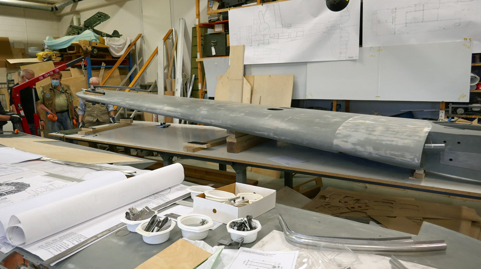
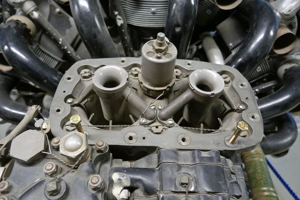
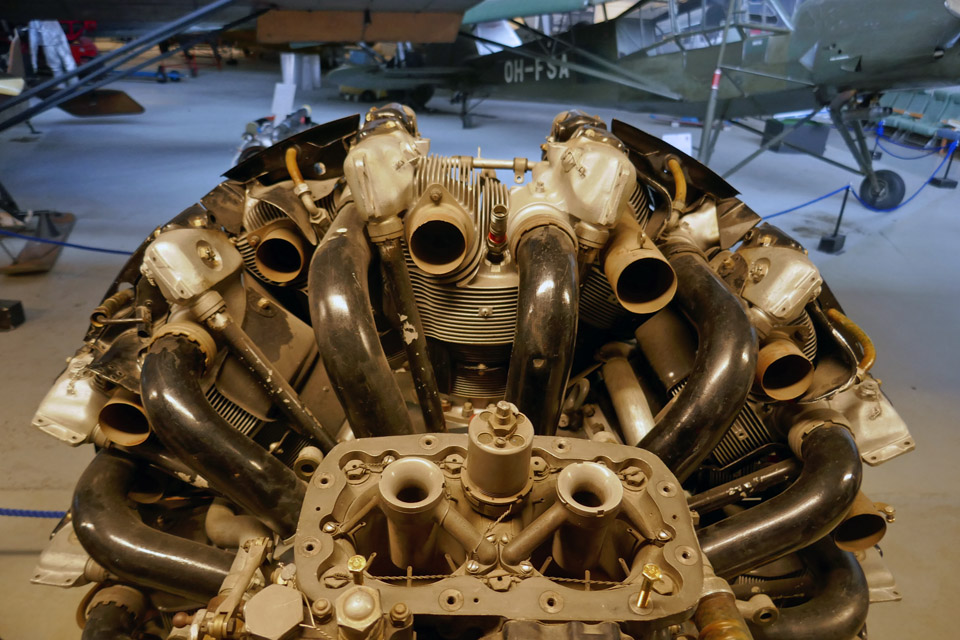
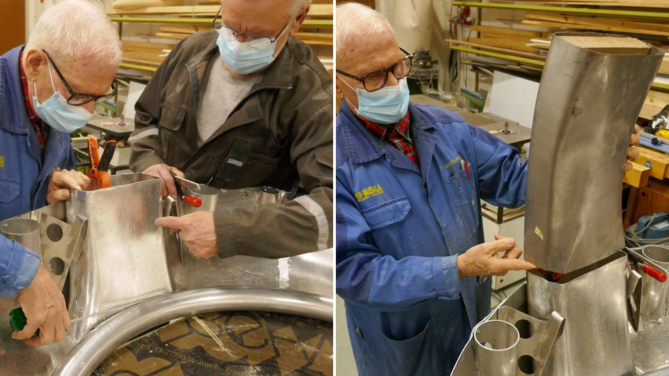
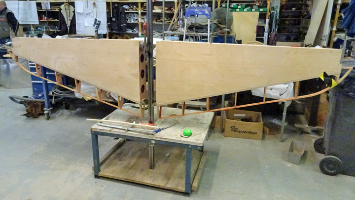
Works on Myrsky carburettor air intake and NACA-ringTiistai 22.6.2021 - Tuesday Club member The half-finished air horn and air intake ducts have been preliminarily assembled on the VL Myrsky II which is under restoration. The Myrsky had a Pratt &Whitney R-1830 radial engine and a similar engine is available at the Finnish Aviation Museum. Fortunately it has been possible to test the assembly at the museum and there is no need to travel to the Air Force Museum at Tikkakoski, where a similar engine has already been installed on the Myrsky’s (MY-14) fuselage.
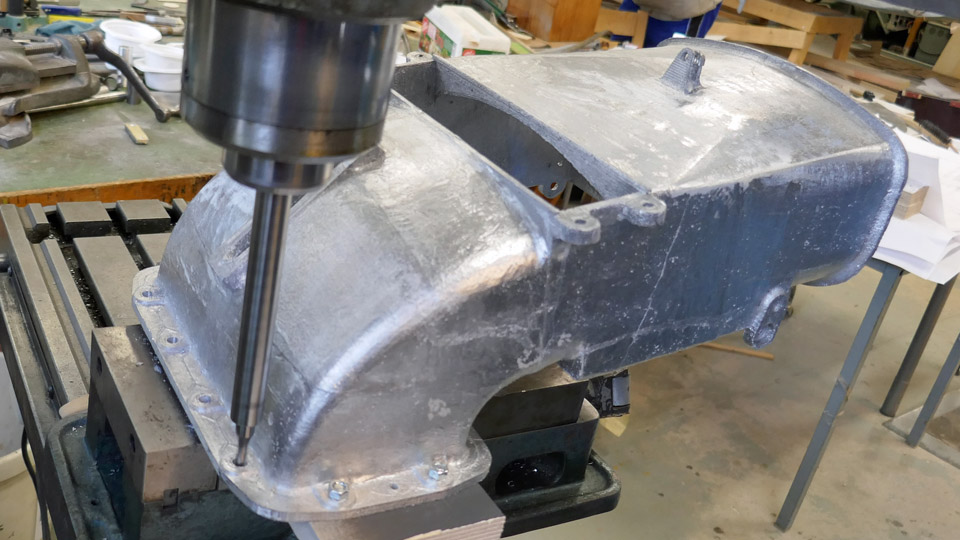
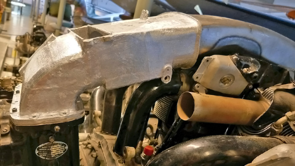
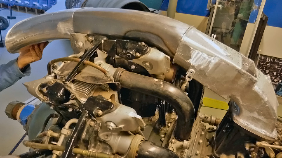
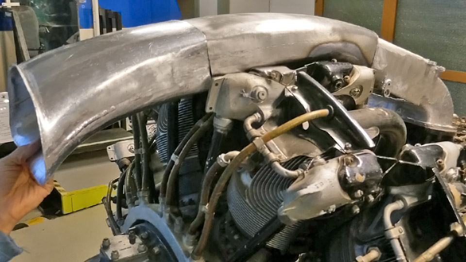
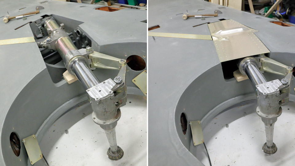
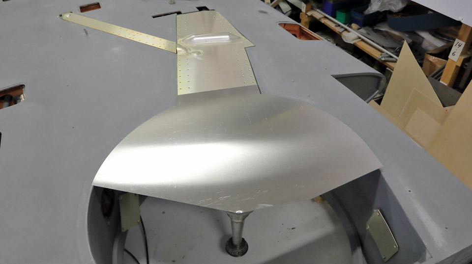
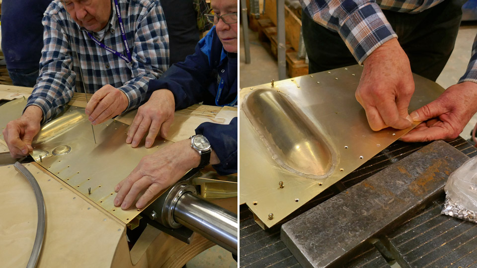
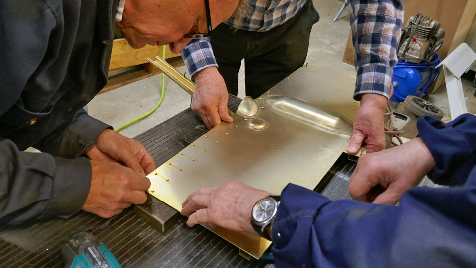
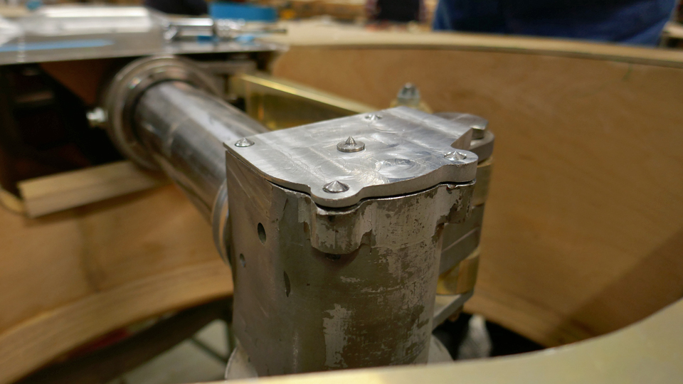
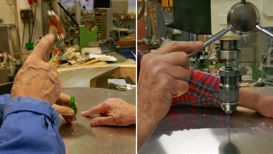
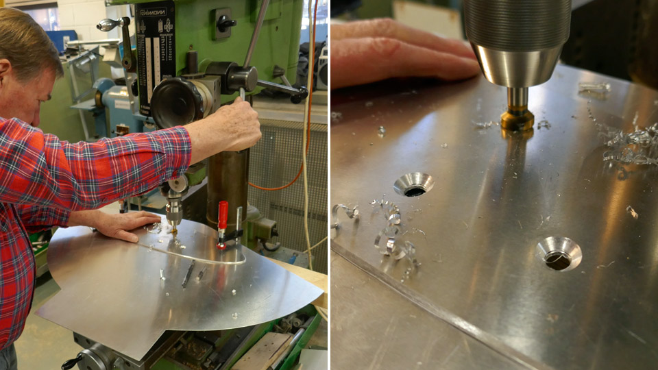
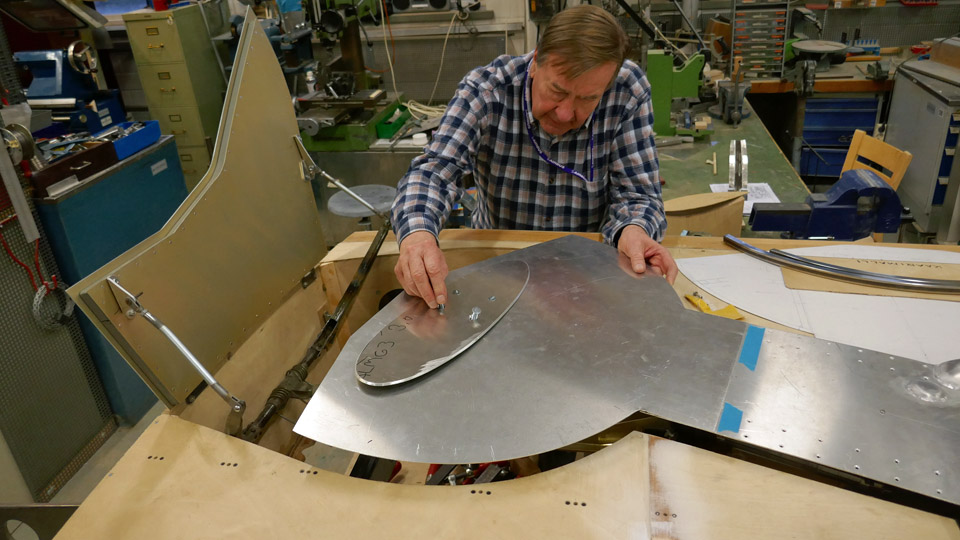
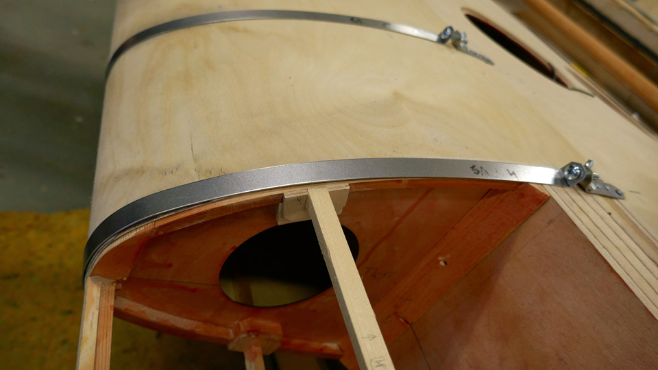
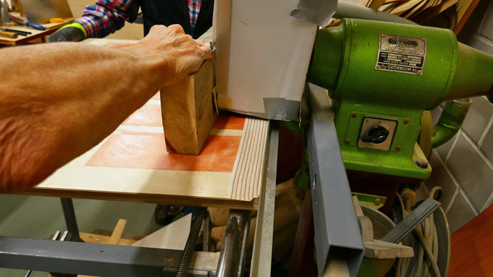
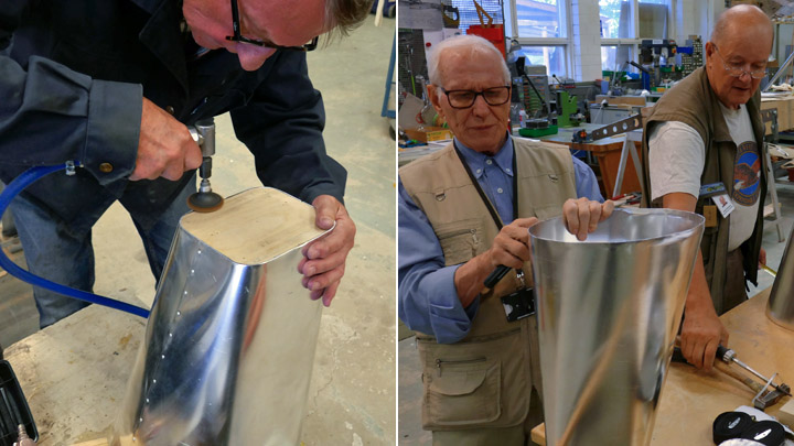
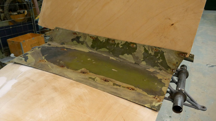
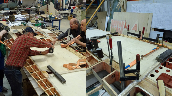
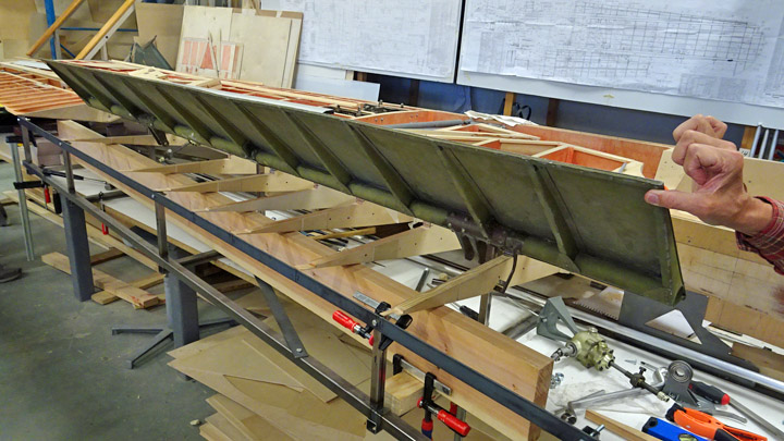
Holes for the fastening bolts were drilled on the cast aluminium air horn and the air horn was fastened with a couple of bolts onto the carburettor of the engine, located in the museum hall. It fitted nicely into its place. Then the two air duct sections could be assembled into place between the air horn and the NACA-ring.
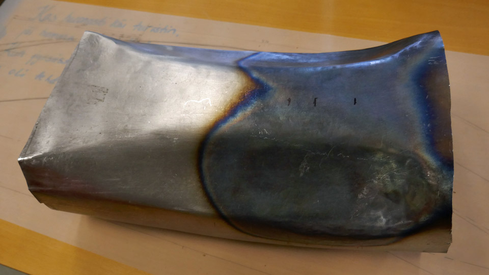
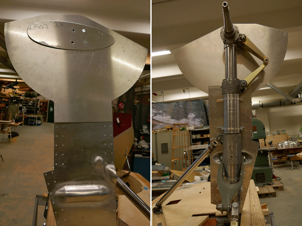
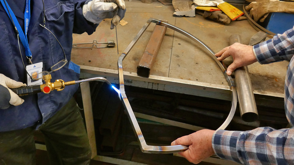
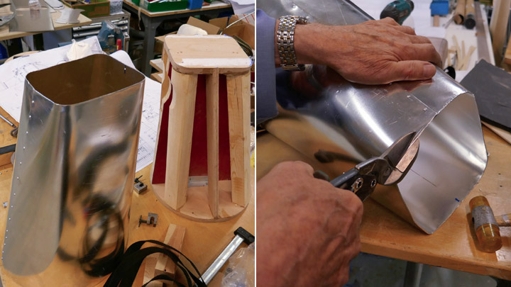
The Tuesday Club team noticed that the section of the air duct, made of steel plate because of its location above the hot engine, did not fit properly. The reducers made on its lower part were too shallow and the air intake duct couldn’t be pressed sufficiently deep between the cylinder head covers. The air intake duct was heated using a welding flame and shaped to fit better. Then the two air intake duct sections were assembled above the engine and fastened on the air horn. Even when half-finished it is a great sight!
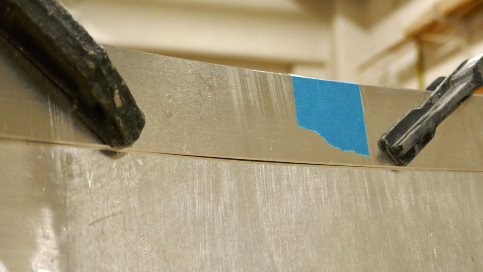
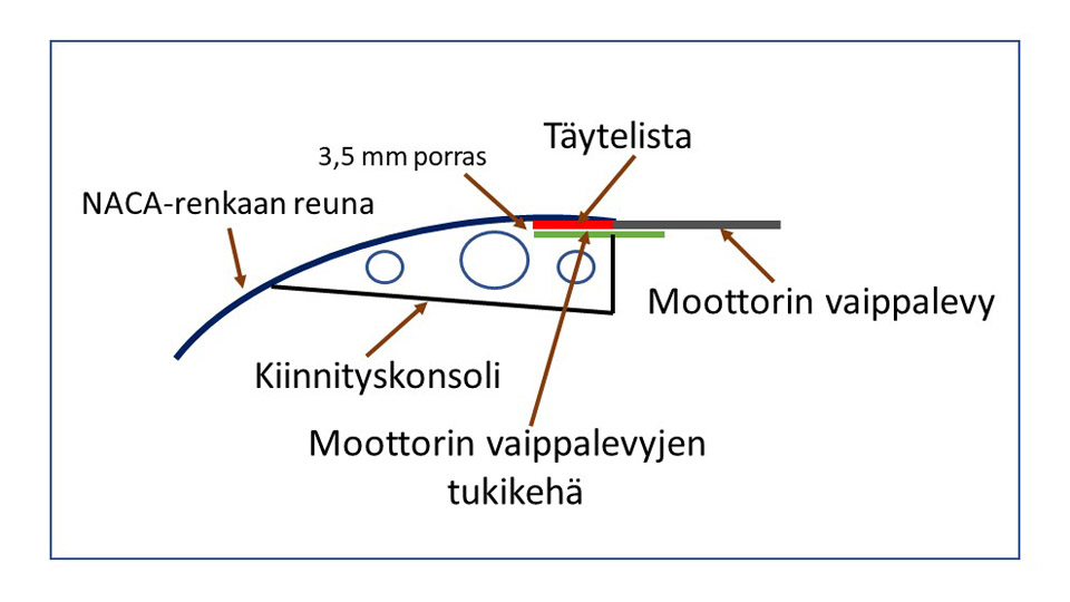
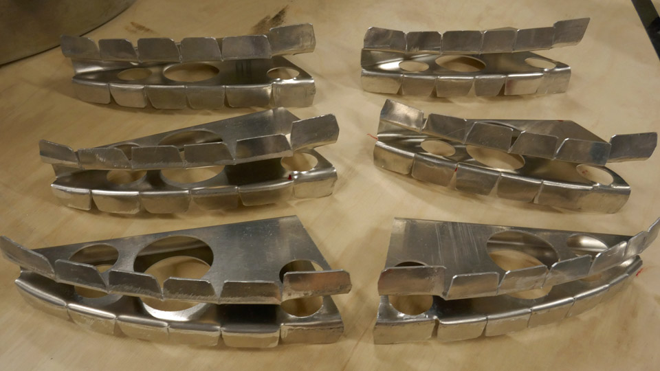
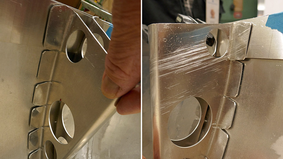
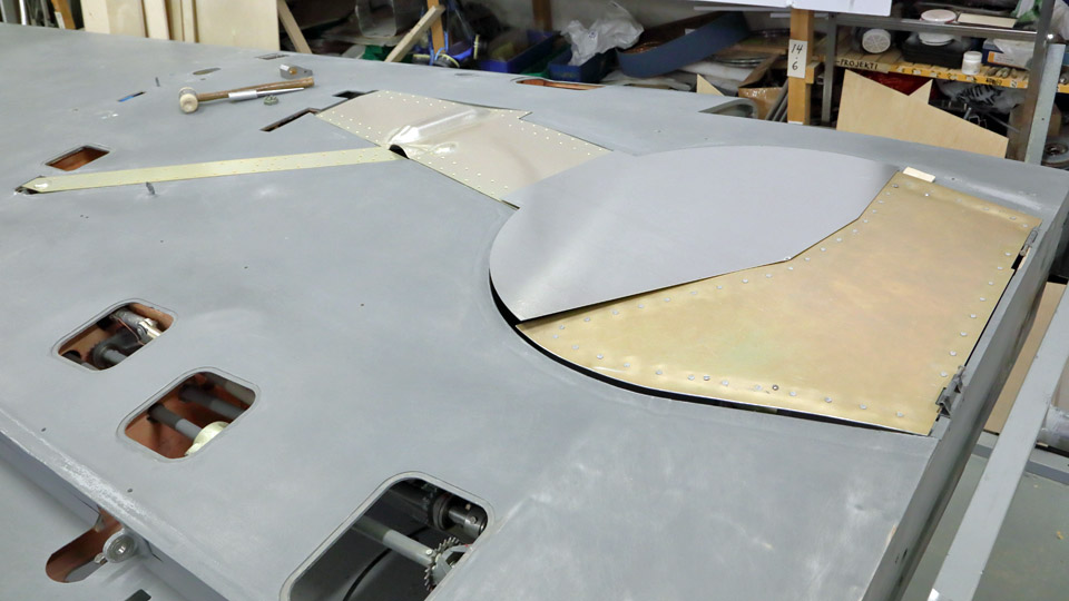
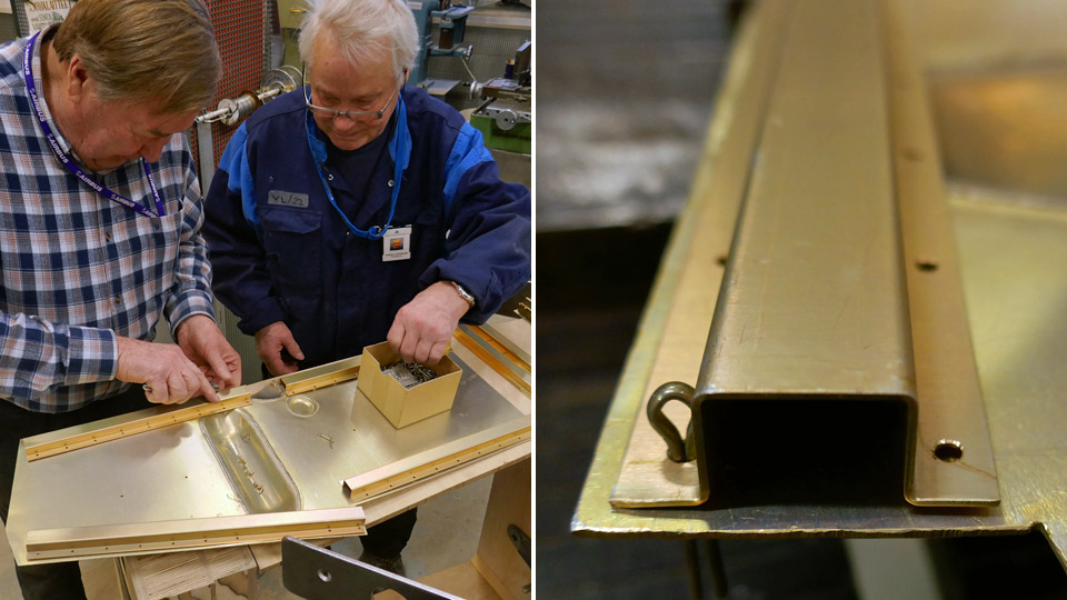
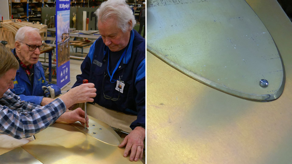
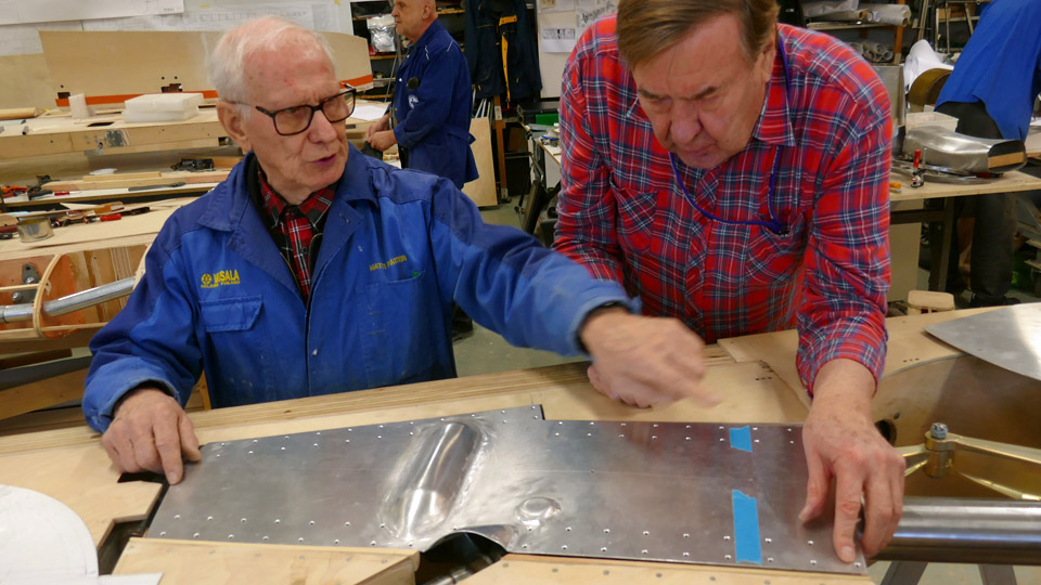
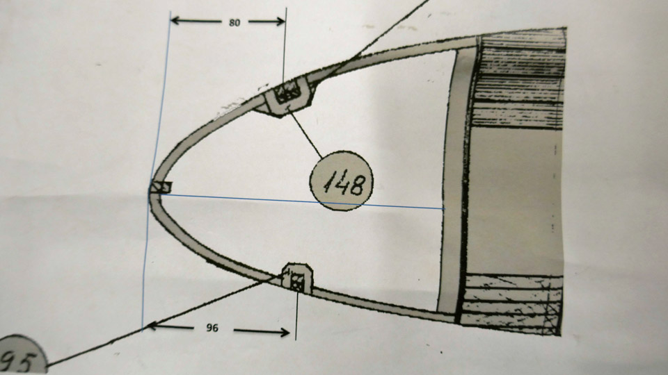
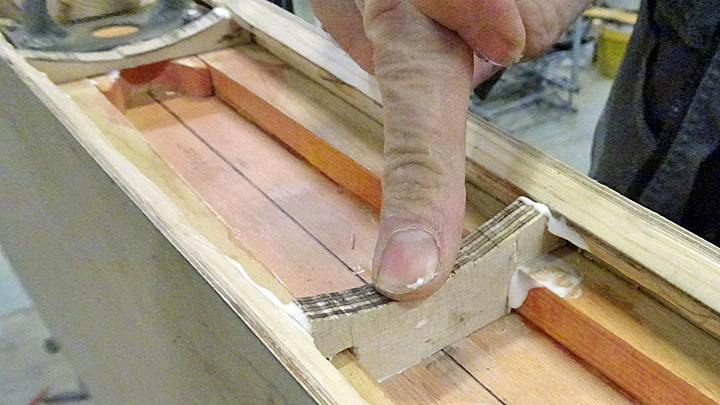
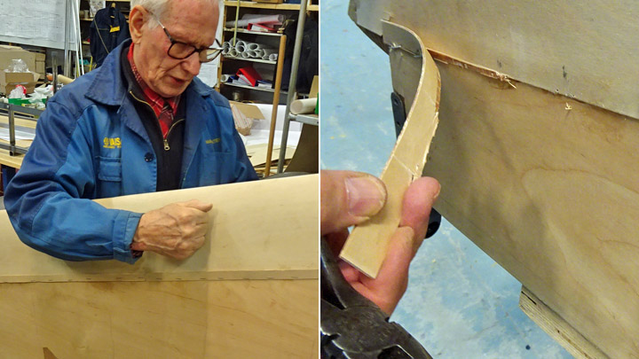
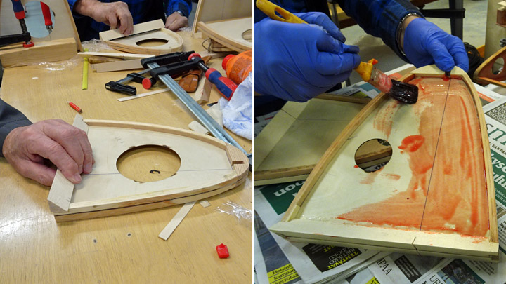
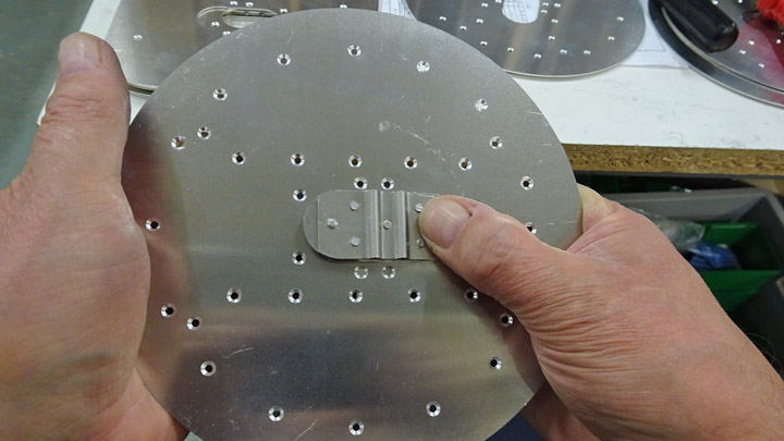
The consoles of the NACA-ring, which are needed to fasten the ring on the brackets on the cylinder heads, had to be modified before riveting on the edge of the NACA-ring. Especially the console hems have needed shaping. The console is riveted on the NACA-ring by its hem. The hem has to meet the curved shape of the NACA-ring and to take into account the filler batten, which is a 2,5 mm aluminium batten riveted on the edge of the NACA-ring, and the 1,0 mm aluminium supporting frame of the engine fairings. The supporting frame is 75 mm wide, and it is riveted on top of the filler batten so that it extends 32 mm outside the edge of the NACA-ring. It forms a shoulder on which the edge of the detachable engine fairing rests and meets the edge of the NACA-ring in a butt joint. There is a very general overview picture of this structure attached.
Translation: NACA-renkaan reuna = Edge of NACA-ring, 3,5 mm porrastus = 3.5 mm offset, Kiinnityskonsoli = Console, Moottorin vaippalevyjen tukikehä = Supporting frame of detachable engine fairing rests, Täytelista = Filler batten, Moottorin vaippalevy = Detachable engine fairing rests.
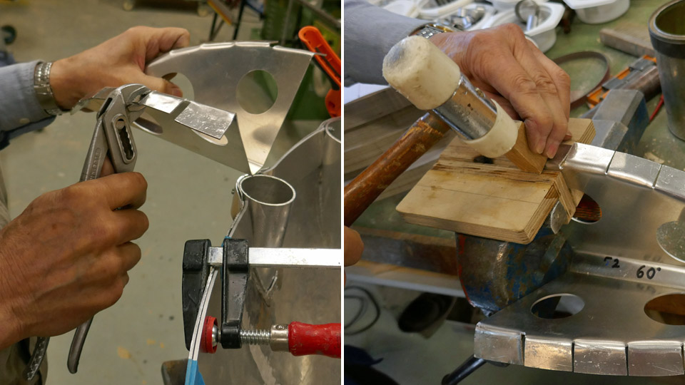
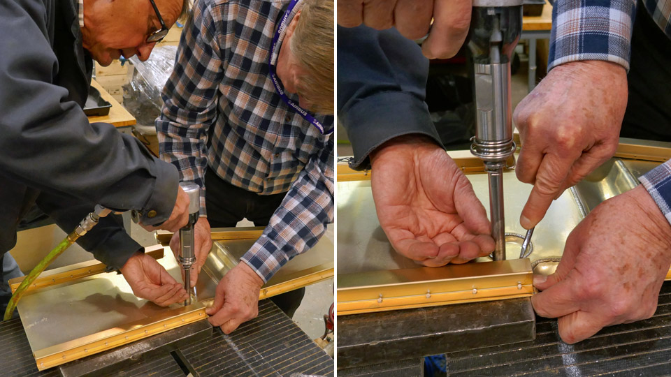
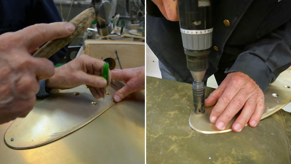
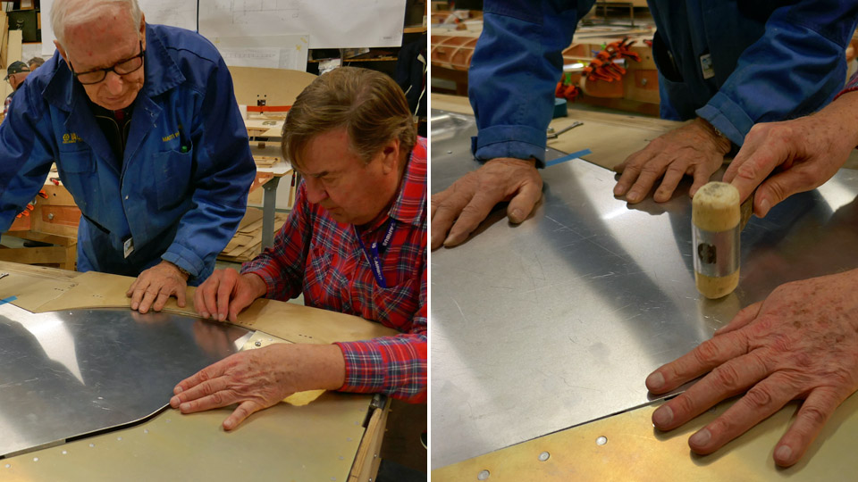
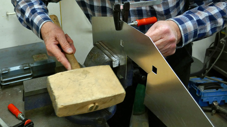
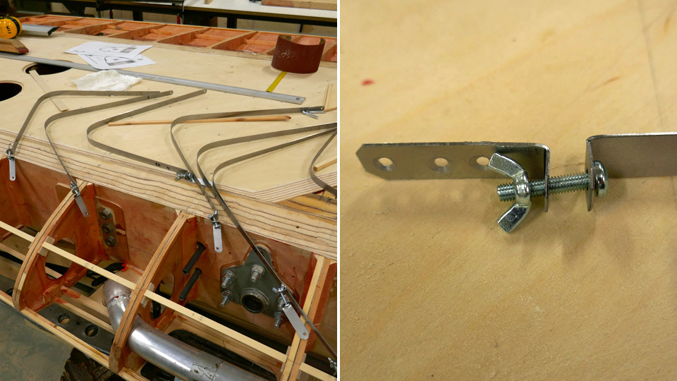
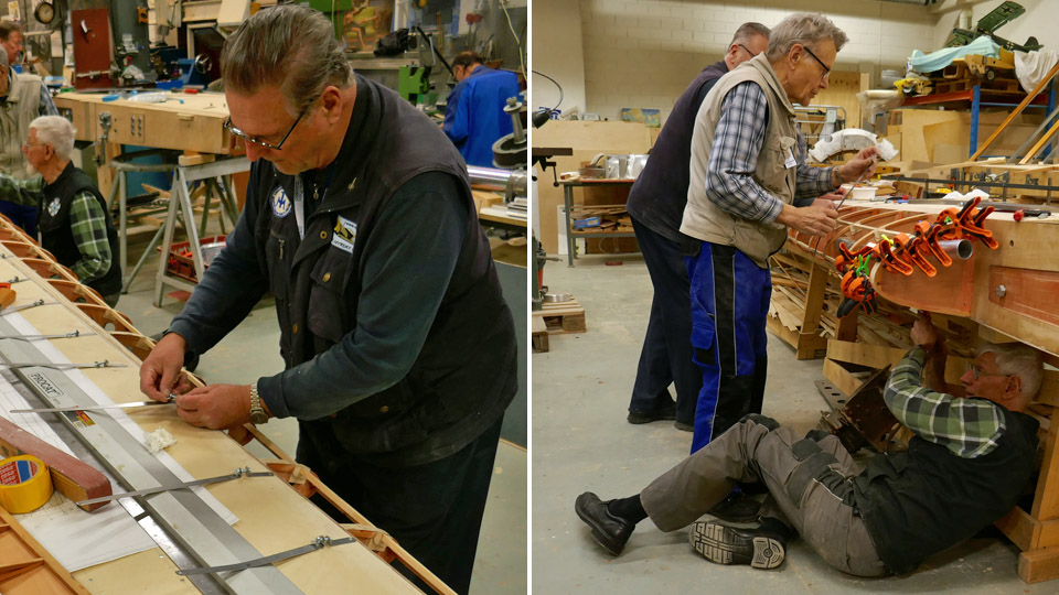
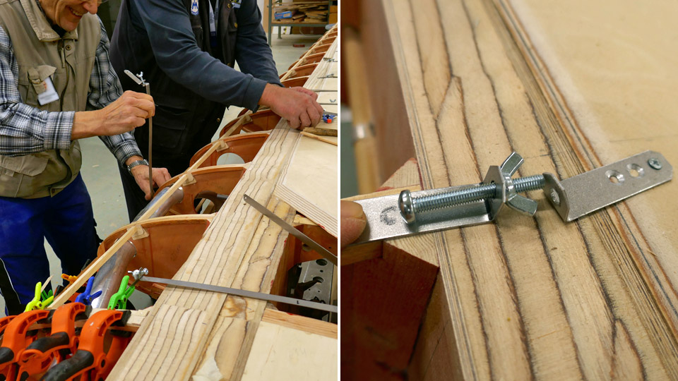
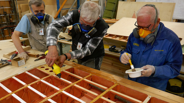
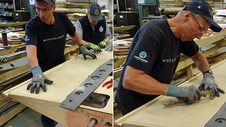
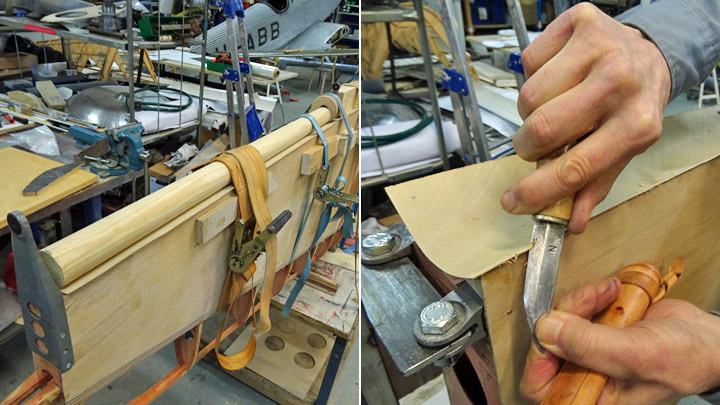
The hems of the NACA-ring consoles were shaped using pliers and a plastic-headed hammer and a piece of wood. A 3,5 mm offset was made on the upper end of the console for the filler batten and the supporting frame. All console hems have now been shaped and are ready to be riveted into place. Before that can be done, the filler batten and the supporting frame on top of it will have to be riveted onto the edge of the NACA-ring. The supporting frame is made of four sections and the sections are ready to be installed.
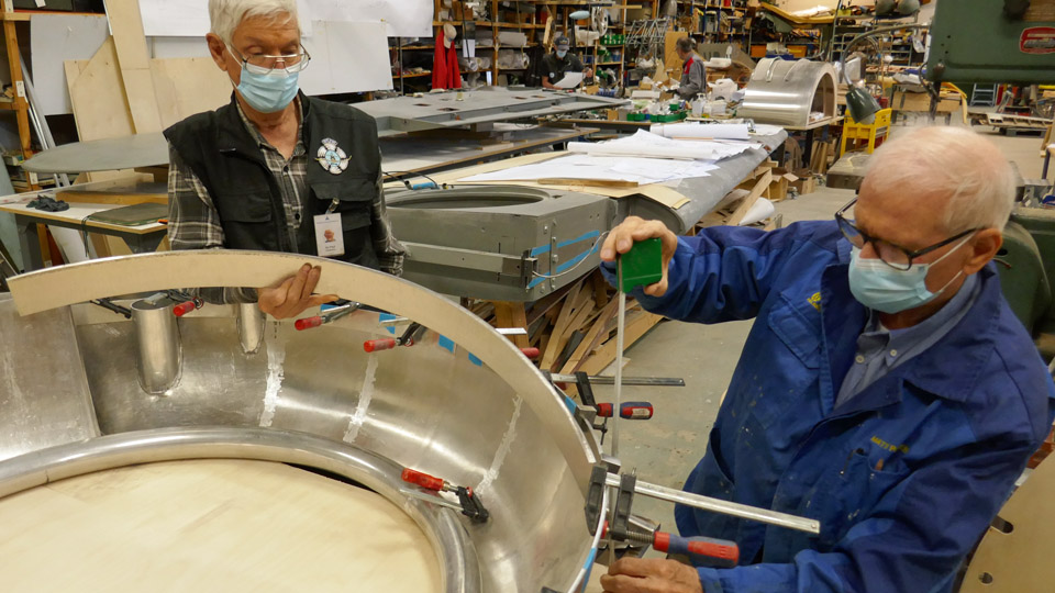
Up to now the filler batten has been fastened on the upper edge of the NACA-ring with clamps. Now it is debated how the riveting of the filler batten and the supporting frame on the NACA-ring edge will be done so that the filler batten settles exactly to the same level as the NACA-ring’s edge. Photos: Lassi Karivalo. Translation: Erja Reinikainen. |
|
Avainsanat: aviation history, restoration, VL Myrsky II, MY-14 |
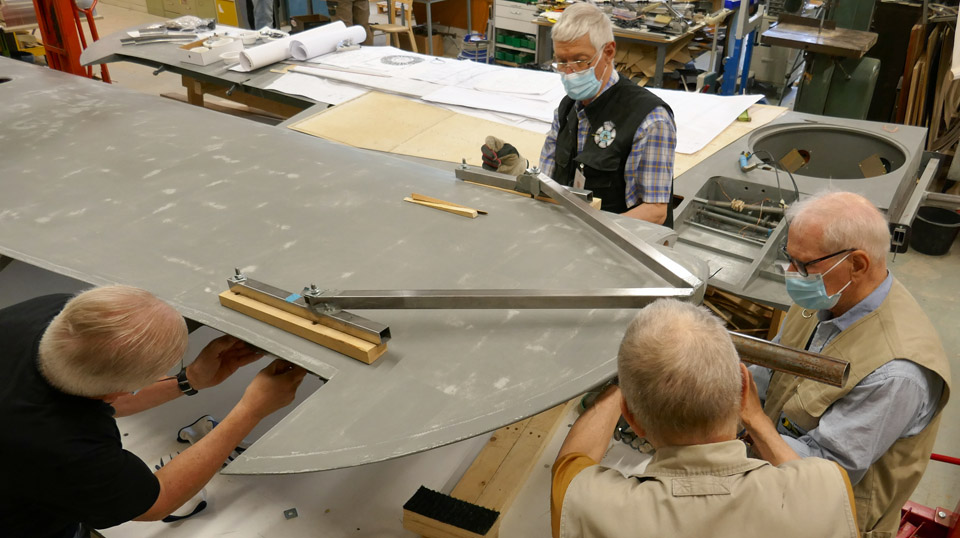
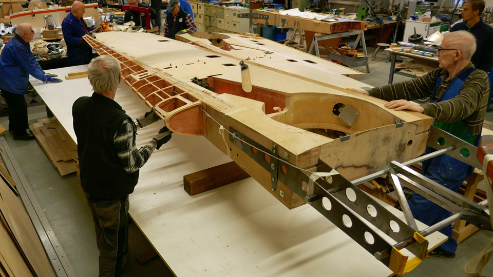
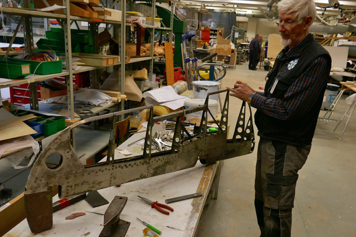
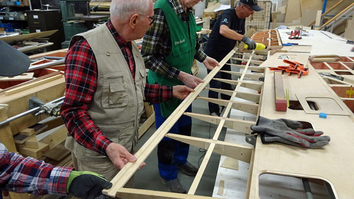
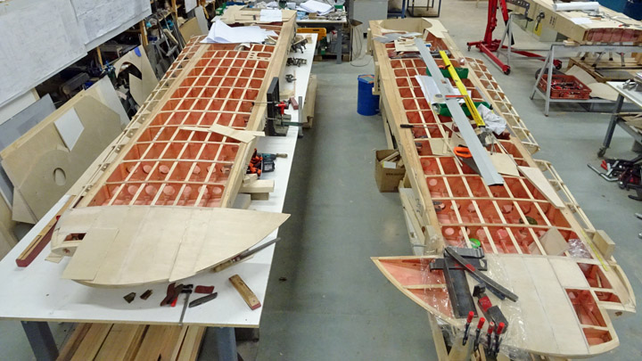
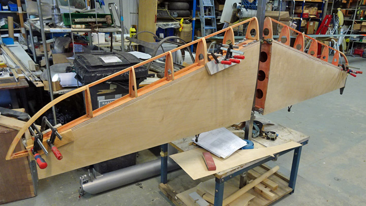
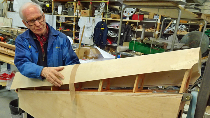
Myrsky's starboard wing half was turned for installing landing gearSunnuntai 13.6.2021 - Tuesday Club member The assembly of the landing gear has been started on the wing halves of the VL Myrsky II (MY-14), which is under restoration at the Tuesday Club. Thorough test assembly has already been done on the test wing which was prepared in the Myrsky-project. The test wing is a 2,5 metres long root piece of the wing, meant mainly for testing the landing gear installation. The landing gear will first be assembled on the starboard wing half.
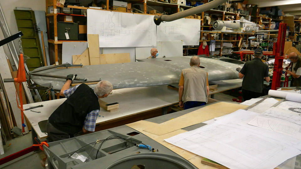
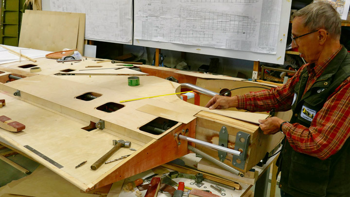
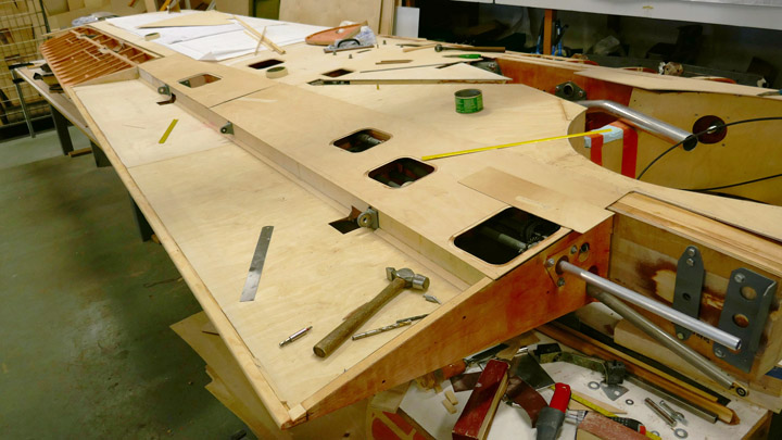
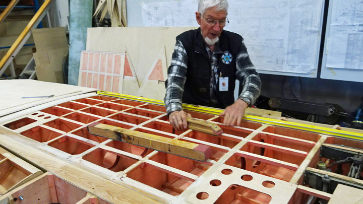
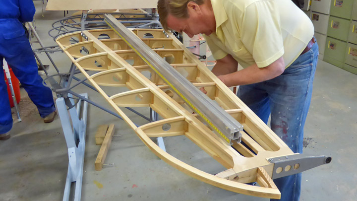
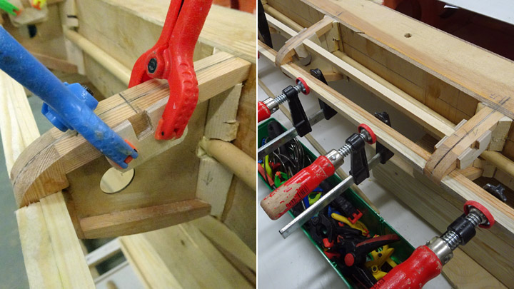
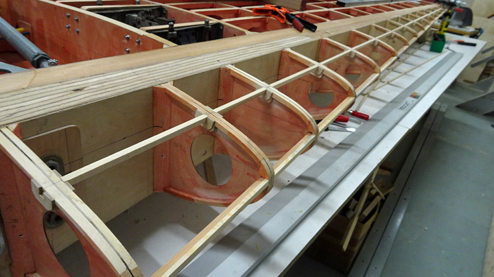
The wing halves were painted with undercoat paint and after this work they remained on the worktable the upper side up. First the starboard wing had to be turned so that the landing gear well is facing upward, and the landing gear can be installed. The wing halves have already been turned around several times during the different work phases. For this purpose steel supports have been made for the wing tip and the wing root and they are used to support the wing when it is lifted and turned.
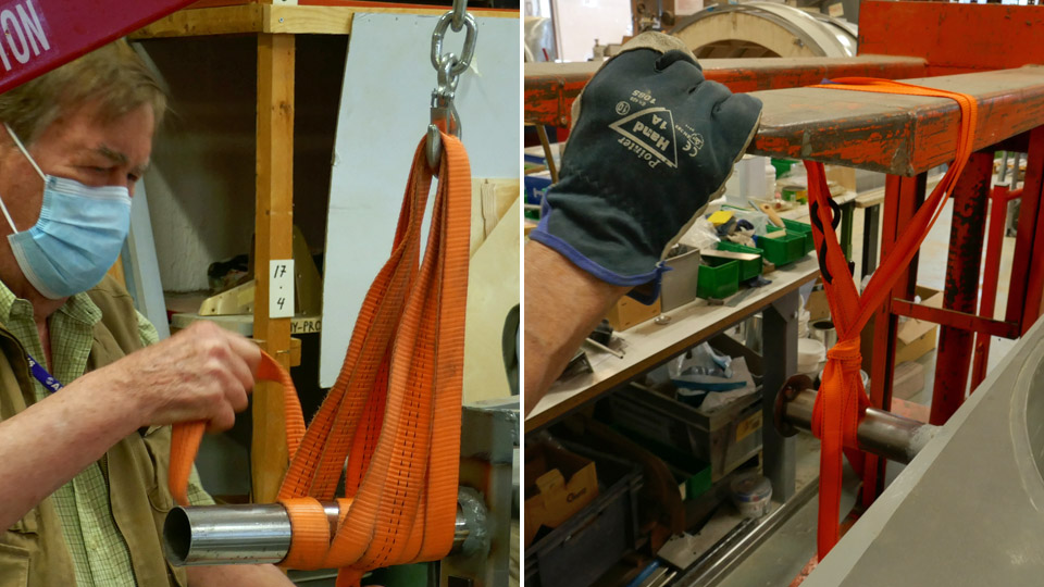
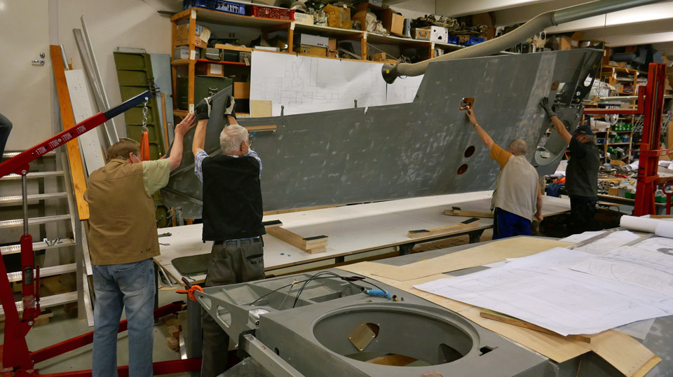
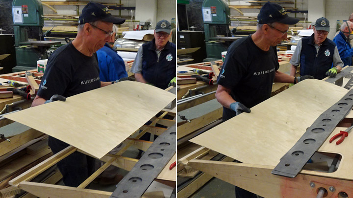
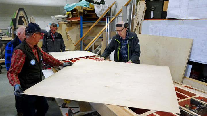
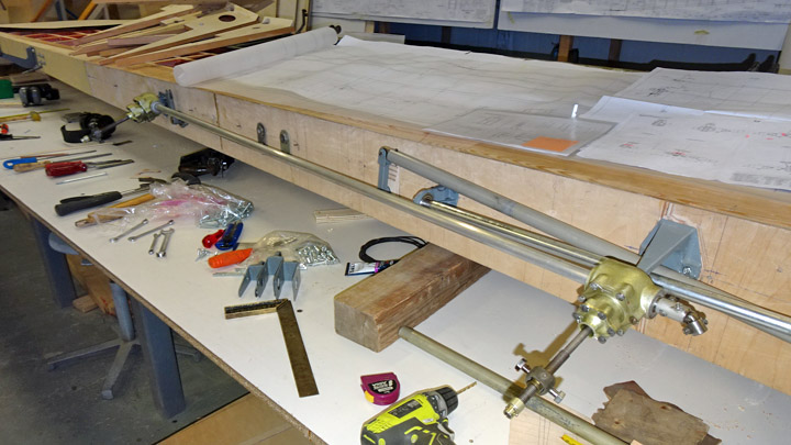
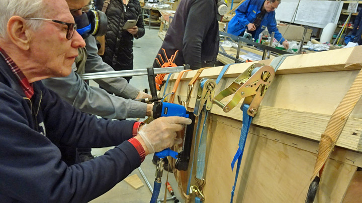
Two lower photos: move the cursor over photo and you will see more photos! The turning supports were fastened on the wing tip and the wing root. Then a lifting device was moved to both ends of the wing and the lifting devices were connected to the steel supports with cargo straps. Then the lifting devices were pumped, and the wing was lifted in the air, supporting it manually all the time. When the wing had been lifted high enough, the wing was tilted in order to turn it around. The wing was carefully manoeuvred onto one side by supporting it from the other side. When the wing had been turned, it was lowered back on the worktable and it was placed horizontally by supporting it at the ribs.
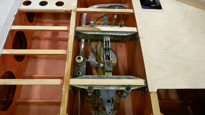
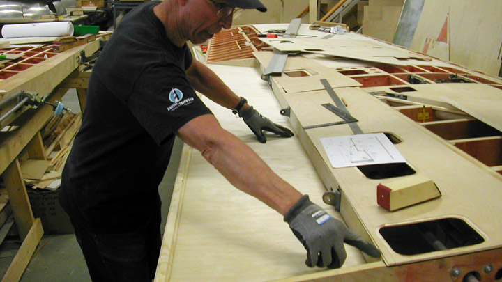
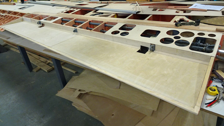
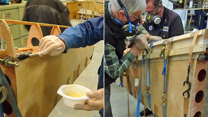
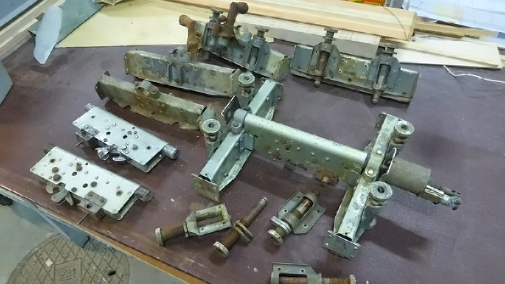
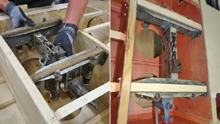
Photos: Jorma Laakkonen. Photo: Jorma Laakkonen. Now the landing gear well was facing upwards, and the landing gear assembly could be started, following the procedure developed when testing the gear on the test wing. The first preliminary test was to place the landing gear oleo strut in the well with its wheel hub and axle. At the same tame the wheel well doors were fitted into place. These include the diagonal support door, the oleo strut door, the wheel hub door and the opening door, which is fastened on the fuselage side edge of the wheel well. All parts seemed to settle nicely into their places.
Photo: Jorma Laakkonen. Now there is ahead the demanding work of fitting all the hinges and fastenings of the starboard landing gear into place so that the landing gear extends and retracts smoothly. The aluminium covers will also have to be assembled into place on the diagonal support, on the oleo strut and on the wheel hub. Another challenge is to fit into place the aluminium cover on the fuselage side of the wheel well and to make its opening and closing mechanism work as planned. This door is opened automatically by a spring lever when the landing gear is taken out. When the landing gear is retracted the wheel presses against a pin in the mechanism and closes the door. Photos: Lassi Karivalo except if otherwise mentioned. Translation: Erja Reinikainen. |
|
Avainsanat: aviation history, restoration, VL Myrsky II, MY-14 |
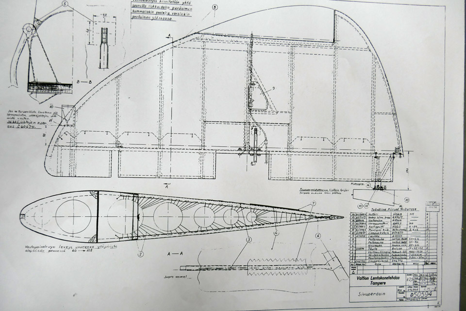
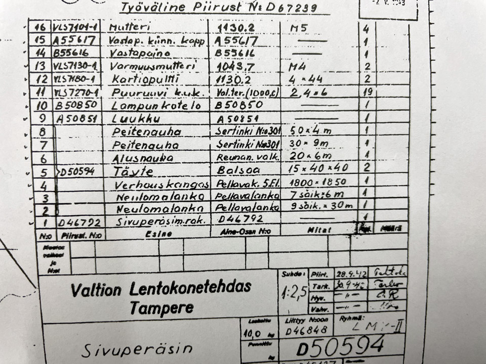
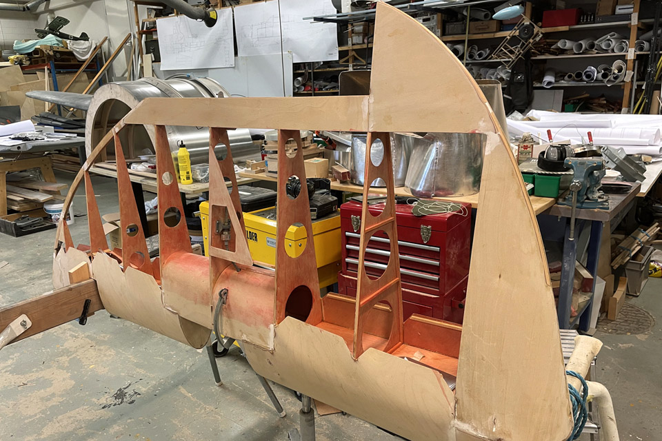
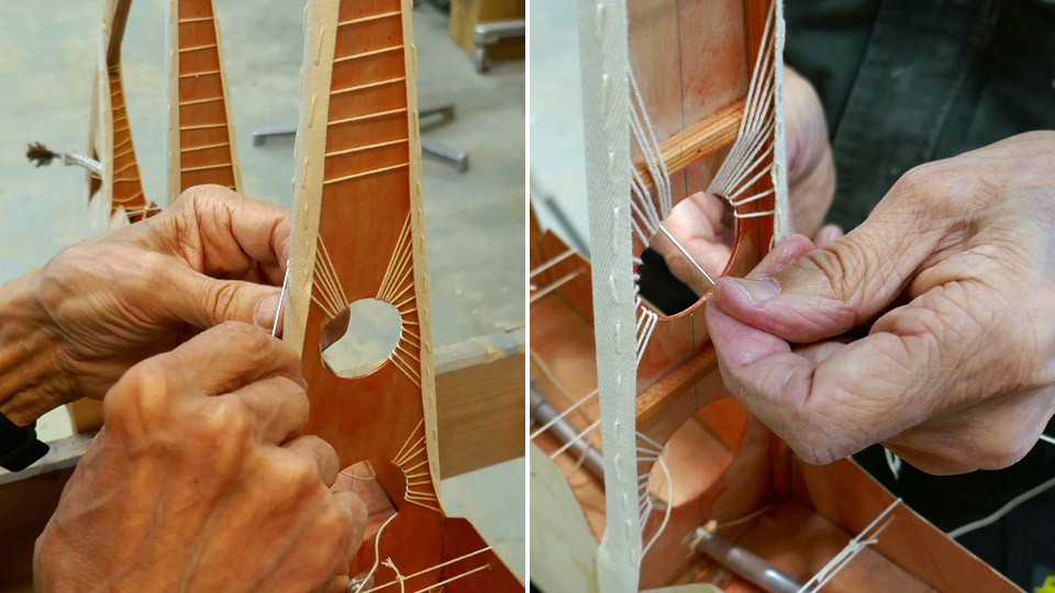
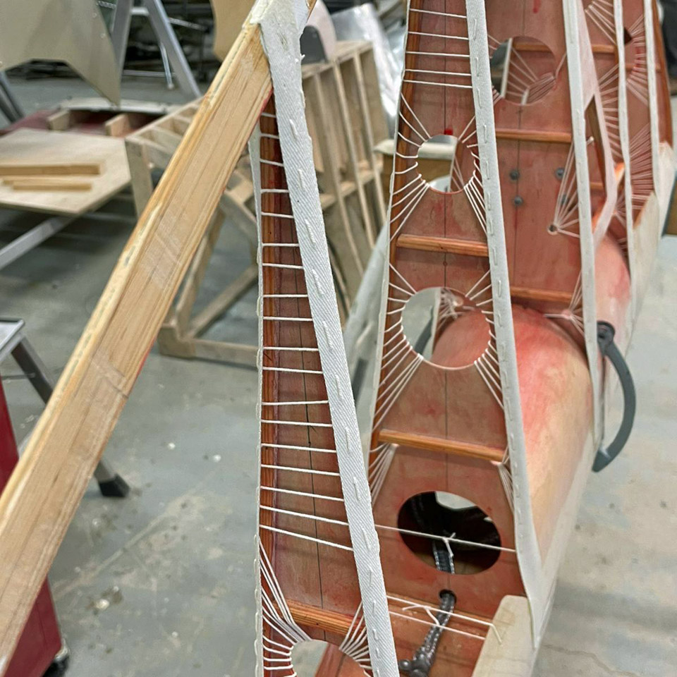
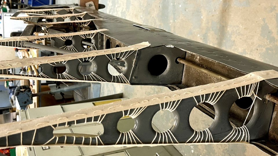
MY-14's vertical stabilizer gets its fabric covering webbing ribbonsSunnuntai 6.6.2021 - Tuesday Club member When the webbing ribbons for the fabric covering had been sewn on the horizontal stabilizer ribs of the VL Myrsky II (MY-14), the sewing work continued on the vertical stabilizer. The vertical stabilizer has a wooden structure, according to the original drawings.
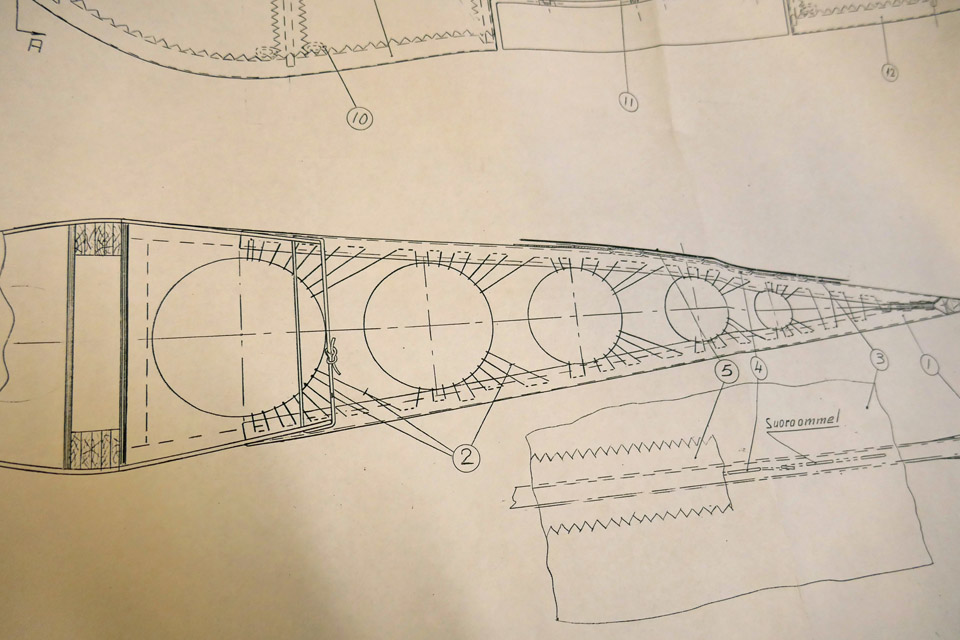
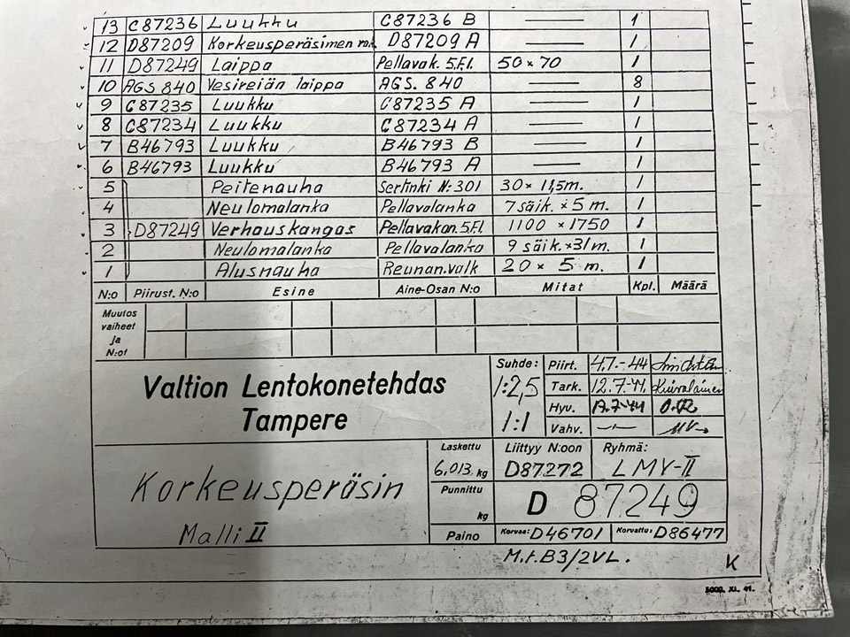
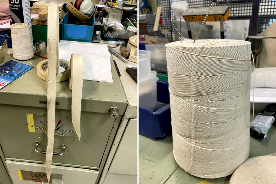
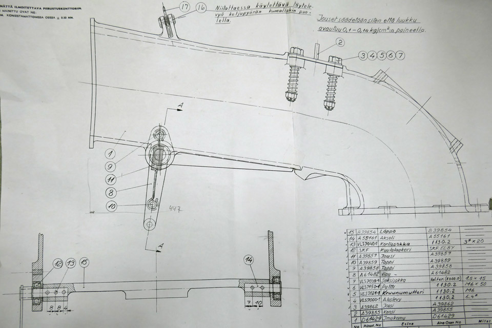
Photo: Heikki Kaakinen. The Tuesday Club team used the original drawing of the vertical stabilizer, prepared by the State Aircraft Factory and dated 30.9.1942, as instructions for the work. The drawing shows very well how the ribbons must be sewn. The bill of materials on the drawing shows a detailed list of the accessories needed in the work. The list includes the covering fabric, the webbing ribbons, cover ribbons and sewing threads. A 20 mm wide diagonally woven linen ribbon was used as the webbing ribbon.
Photo: Heikki Kaakinen.
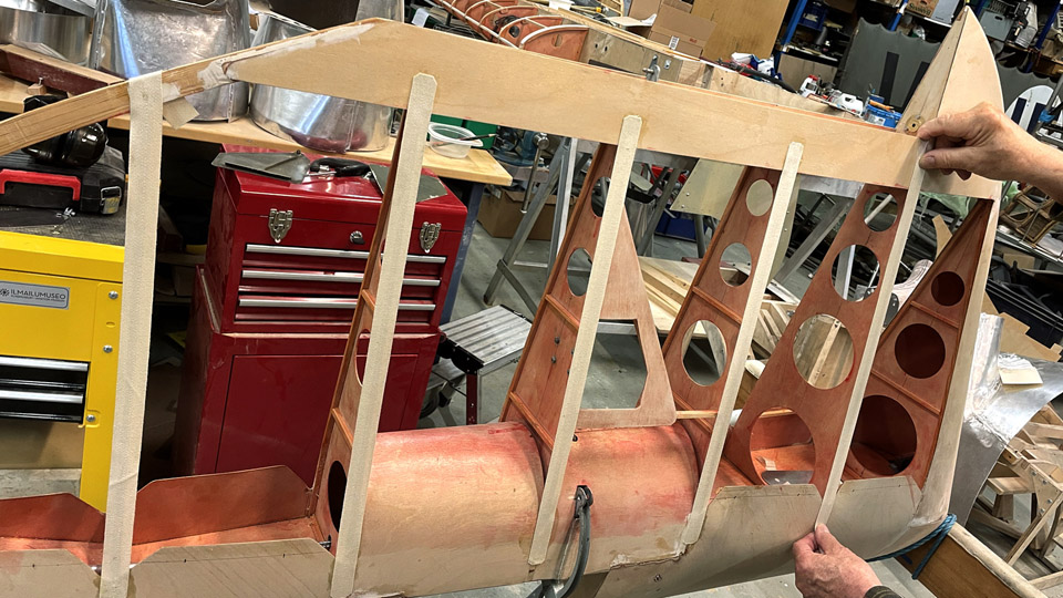
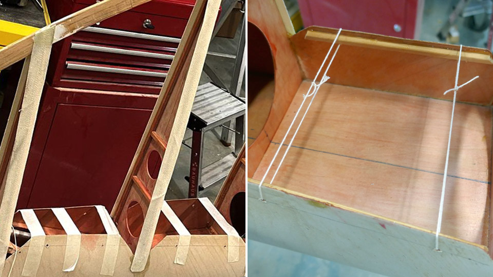
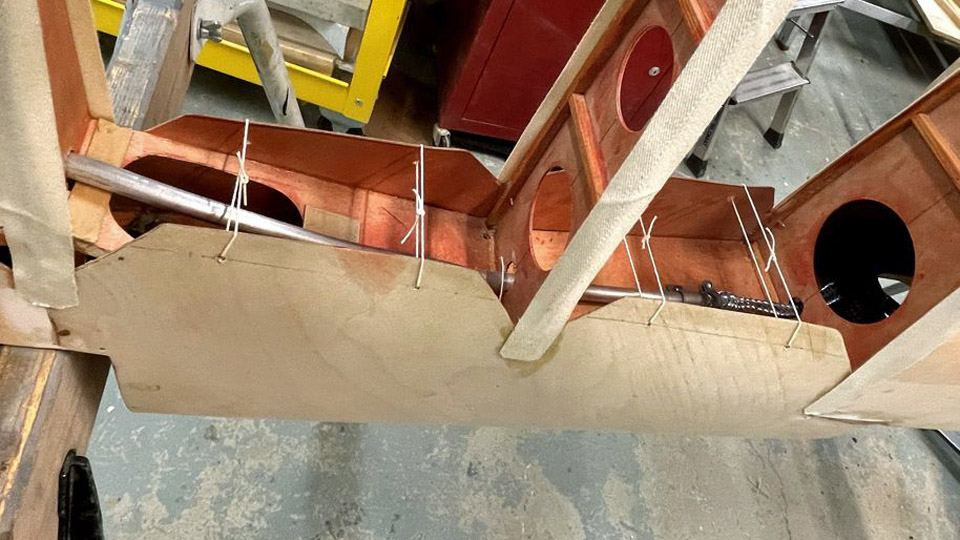
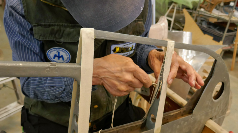
Photo: Heikki Kaakinen. In order to keep the webbing ribbons in place on the rib of the vertical stabilizer when doing the sewing, the ribbon was stretched on the rib and its one end was glued on the plywood of the leading edge and the other end on the plywood of the trailing edge. Contact glue was used in this work.
Left photo: Heikki Kaakinen. One more work phase had to be completed before the actual sewing could be started. The edges of the plywood sheet covering the leading edge had to be bent inwards so that the edges won’t chafe the fabric covering and gradually damage it.
Photo: Heikki Kaakinen.
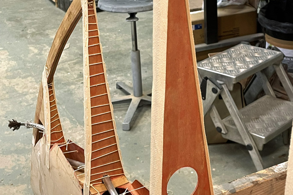
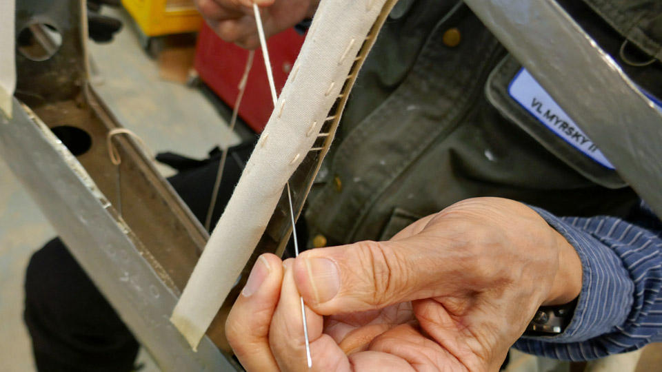
Photo: Heikki Kaakinen. To bend the plywood edges, 3 mm holes were drilled where the drawing indicated. Then the edges were bent against each other and tied temporarily into this position using painter’s tape. Linen thread was pulled through the drilled holes and then the threads were tied together into a tightening loop, connecting the edges of the plywood. Then the supporting painter’s tapes could be removed, and the sewing of the webbing ribbons could be started.
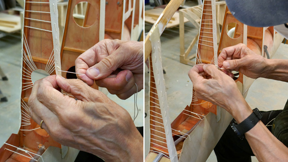
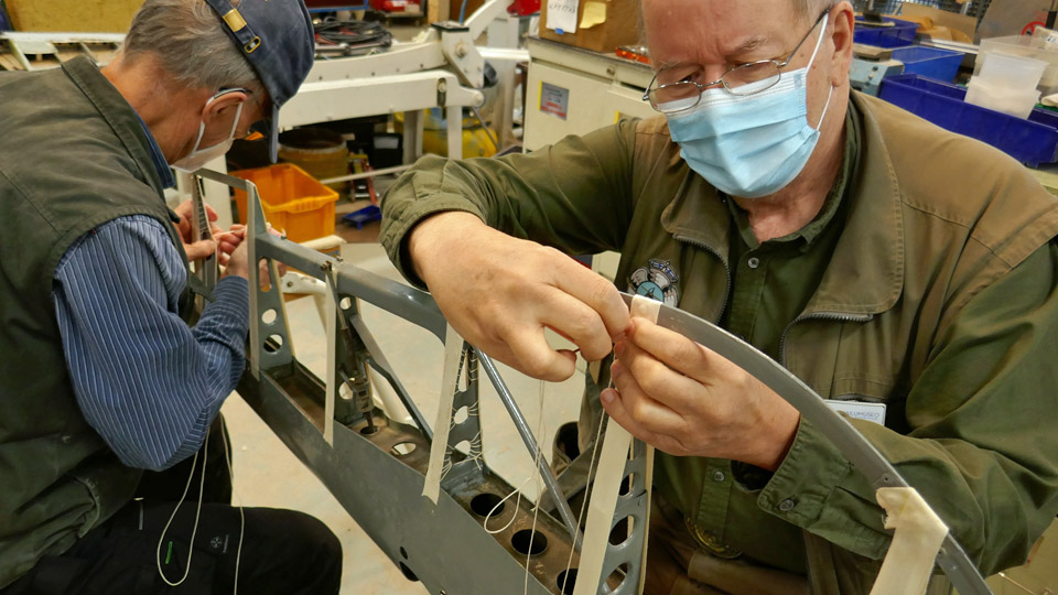
Photo: Heikki Kaakinen. The webbing ribbons for the fabric covering of the vertical stabilizer were sewn in a similar manner as on the horizontal stabilizers. At the tapered part of the rib the edges of the ribbon were stitched together. At the broader part of the rib, where the round lightening holes are, the thread was slipped through the lightening hole and fastened on the ribbon’s edge on the other side and repeating back again. A radial pattern of the threads was formed in the lightening hole. Now the vertical stabilizer had its webbing ribbons in place. Photos: Lassi Karivalo except if otherwise mentioned. Translation: Erja Reinikainen. |
|
Avainsanat: aviation history, restoration, VL Myrsky II, MY-14 |
Webbing ribbons for fastening fabric covering of Myrsky's horizontal stabilizer are sewnTiistai 1.6.2021 - Tuesday Club member The VL Myrsky II fighters had originally wooden horizontal stabilizers. The aeroelastic flutter caused the damaging and even breaking of the stabilizers. Therefore the Myrsky’s horizontal stabilizers were replaced with metal stabilizers, which endured the flutter. The documents concerning the MY-14 which is under restoration don’t mention whether the aircraft got metal horizontal stabilizers before it was written off. However, the board of the Myrsky restoration project decided that the restored MY-14 would have metal horizontal stabilizers. One of the reasons for this was that there were original metal stabilizers available, but somewhat damaged and without covering.
Photo: Heikki Kaakinen. The original horizontal stabilizers with aluminium structure have already been repaired and painted by the Tuesday Club and they have been waiting for the fabric covering for a while. The metal stabilizers are covered with fabric in the same way as the corresponding wooden stabilizers. First fabric webbing ribbons are sewn on the ribs of the stabilizer. The fabric covering is fastened on these ribbons by sewing. The fabric is tightened using several layers of nitrocellulose varnish and finally painted according to the aircraft’s paint scheme.
Photos: Heikki Kaakinen. The Tuesday Club team has now started the sewing of the webbing ribbons on the MY-14’s horizontal stabilizers. To make the work easier, one of the stabilizers was fastened into an upright position against two trestles. The first step was to stretch a 20 mm wide linen upholstery webbing ribbon on the stabilizer’s ribs. This was done by gluing the ends of the ribbon on the rib at the leading edge. This way the ribbon will stay in place when sewing it onto the ribs.
After the gluing the sewing could be started. The instruction drawing for sewing the ribbons on the wooden horizontal stabilizers was applied, because the instructions for the metal stabilizer have not been preserved. According to the instructions multithreaded 0,5 mm linen thread was used in the sewing work.
The sewing work was started at the trailing edge end of the rib. The edges of the ribbon stretched on the upper and lower edge of the rib were stitched together. This was the method used at the tapered end of the rib where there are no lightening holes.
When the work reached the broader part of the rib where the round lightening holes are, the sewing method was changed. Now the thread fastened to the edge of the ribbon was slipped through the lightening hole and to the other side to the ribbon’s edge, and back again. The webbing ribbon was sewn onto the rib following the original instructions, weaving the thread through the lightening hole.
Photo: Heikki Kaakinen. When the ribbons had been sewn on all the ribs of one stabilizer, the procedure was repeated on the other stabilizer. Now the horizontal stabilizers are ready for fastening the fabric covering. In the original drawing’s instructions the fabric quality has been defined as linen fabric 5.F.I. Photos: Lassi Karivalo except if otherwise mentioned. Tranlation: Erja Reinikainen |
|
Avainsanat: aviation history, restoration, VL Myrsky II, MY-14 |
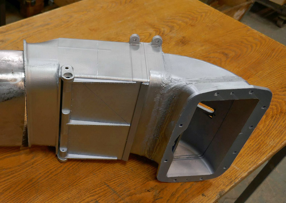
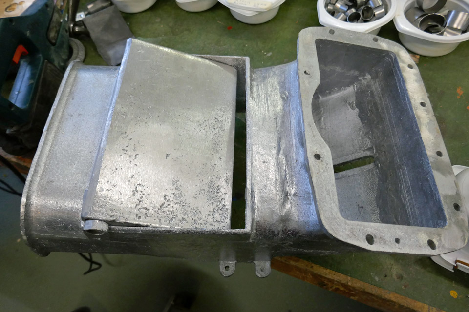
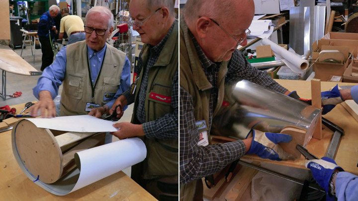
Myrsky engine's air horn and air intake are madePerjantai 28.5.2021 - Tuesday Club member The air flow entering an aircraft’s carburettor is controlled in the air horn, which is attached to the carburettor. When necessary, there is an air intake duct connected to the air horn. This is the case in the VL Myrsky II fighter, among others. In the Myrsky the two-sectioned air intake duct is connected to the air intake, located at the top of the NACA-ring, and is led between the upper cylinders to the air horn of the two-throat carburettor behind the radial engine. The suction air flow is controlled with the damper located in the air horn as well as the warm air flow, which comes through the engine space and protects the carburettor from freezing.
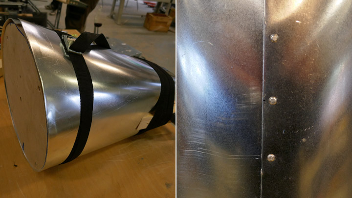
The Myrsky’s air horn is made of cast aluminium. The front piece of the two-section air intake duct, which is fastened on the NACA-ring, is made of aluminium plate. The tail section of the air intake duct is made of steel plate because it is located at a hot place between the cylinders. The tail section of the duct also connects the front section of the air intake duct to the air horn and is fastened to them with fastening clamps.
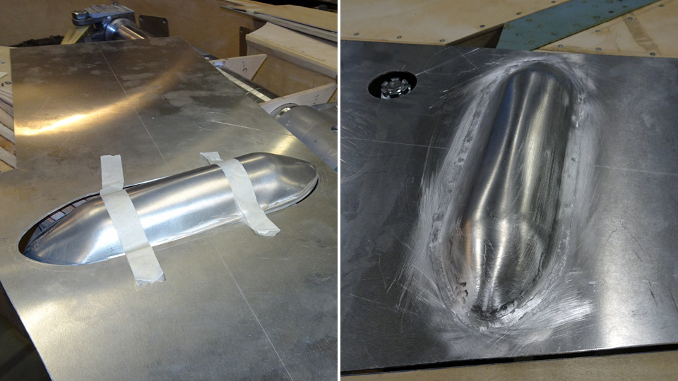
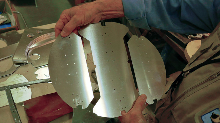
No original Myrsky engine’s air horn or parts of the air intake duct have been preserved and they had to be made in the restoration project of the MY-14. The sections of the air intake duct have already been made. The front section of the duct was made according to the drawing from 1,0 mm thick aluminium plate, using a mould. The tail section was made from 1,0 mm thick steel plate. The sections of the air intake duct have been fitted into place and the front section of the duct is being fastened to the opening in the NACA-ring.
The SASKY Municipal Education and Training Consortium at Sastamala helped to manufacture the air horn from cast aluminium. They were interested in the ongoing Myrsky restoration project and asked if there was some restoration work which could be made as 3d-printing by the SASKY students. The Tuesday Club team suggested that they could make the rather difficult air horn - and they accepted the challenge.
Photo: SASKY
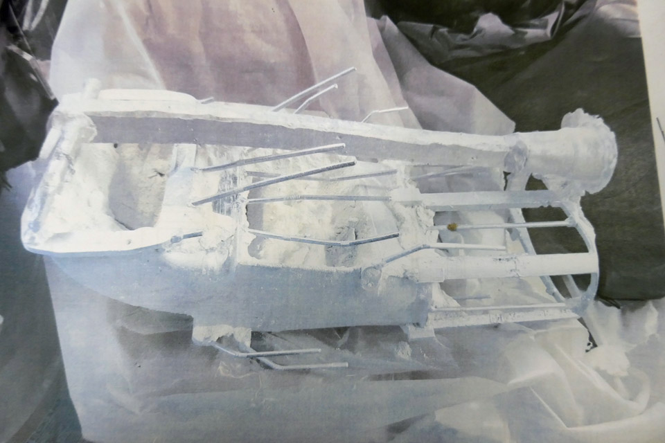
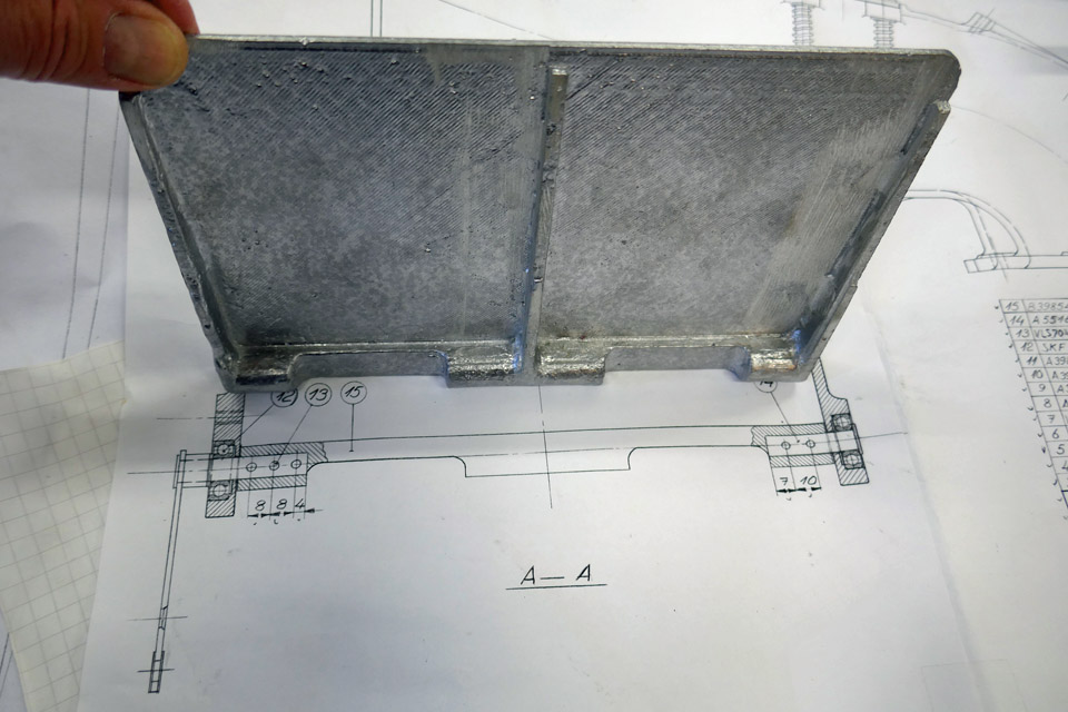
The project was started at SASKY by 3d-printing a plastic 1:1 scale model of the Myrsky’s air horn according to the drawings. Then the actual cast mould for the aluminium cast was made based on the 3d-print. The 3d-printed model was dipped several times in a ceramic solution and a ceramic layer was formed, layer by layer, on the plastic model. Flow channels and air extract were also made on the cast mould. Then the plastic 3d-model was melted from inside the ceramic shell, and the cast mould for the air horn was ready. The liquid AlSi 12 aluminium was poured into the mould. When the aluminium had cooled the mould was broken and the flow channels were removed, and the surface was ground smooth.
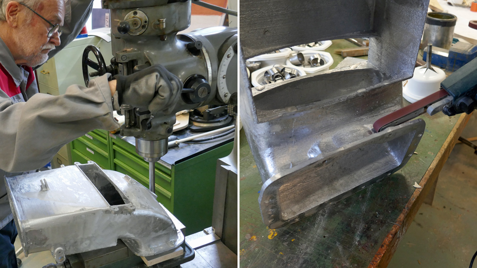
The cast aluminium air horn is now at the Tuesday Club and is ready for further work. Some extra material has been ground off. Holes for fastening bolts will be drilled. The Tuesday Club wishes to thank the SASKY Municipal Education and Training Consortium for preparing the aluminium cast of the air for the restoration the restoration project of the VL Myrsky II (MY-14). Photos: Lassi Karivalo except if otherwise mentioned. Translation: Erja Reinikainen. |
|
Avainsanat: aviation history, restoration, VL Myrsky II, MY-14 |
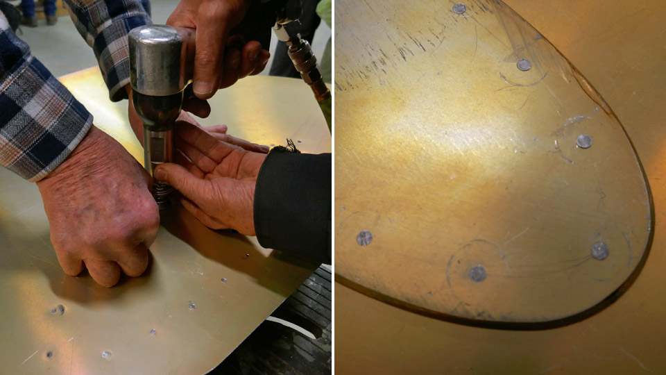
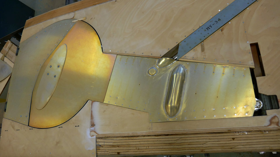
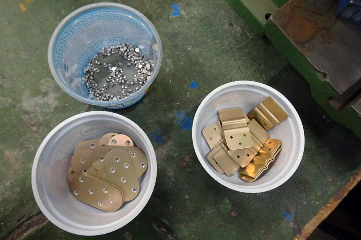
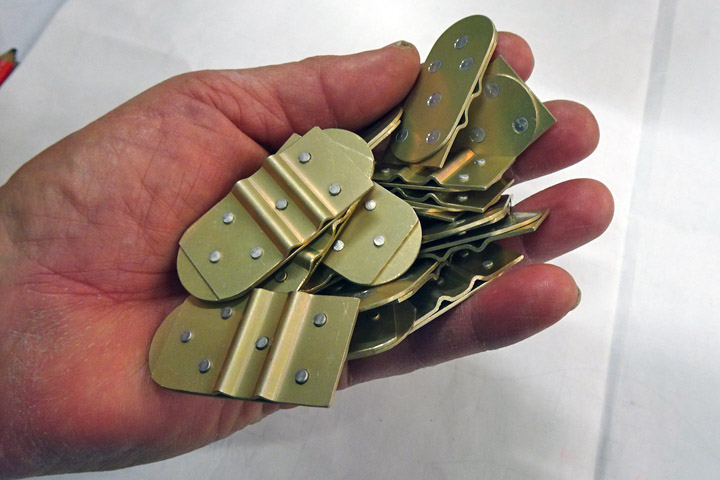
Stiffeners are fastened on Myrsky?s wheel and oleo compartment doorsTiistai 14.4.2020 - Member of Tuesday Club The VL Myrsky (MY-14) is being restored and its parts around the wheel well, including the outer door of the wheel well, the door of the oleo compartment and the door stiffeners were sent to be chromated. When they came back from the chromating process, it was time to fasten the stiffeners on the doors. Chromate bathing means that the aluminum plate is treated with acid solutions containing chromates and a thin inorganic film is formed on the surface of the aluminum with the components of the surfacing bath liquid. This surfacing protects the aluminum plate from oxidization. In the chromate process the Myrsky’s landing gear doors and their parts got a beautiful golden hue on the surface.
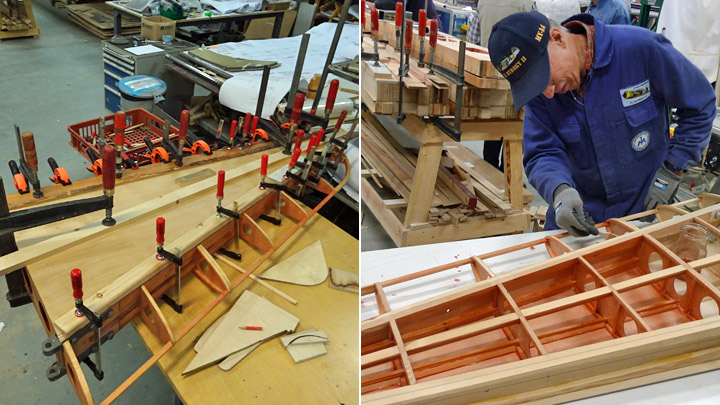
First the stiffening battens were fastened on the landing gear oleo compartment door. The battens have top hat profile. This means that the square batten is open at the bottom and it has sleeves bent to the sides. The sleeves have holes for riveting the stiffening batten on the edges of the door.
The holes for the rivets had already been drilled earlier on the oleo compartment door and on the stiffening battens. The rivet holes on the edges of the door had also been beveled for flat head rivets. The stiffening battens were riveted on the lower side of the door. The work was started by fastening the battens into place with a couple of pins which were pushed through the rivet holes. Before riveting the battens the oleo compartment door was assembled into place and the team made sure that it fitted properly in its place also with the stiffening battens.
Then the battens were riveted on to the inner side of the door, rivet by rivet, using the riveting gun. The riveting gun is faster and more practical than using a hammer for the riveting work. When all the stiffening battens had been fastened on the oleo compartment door, the work on the stiffeners for the door on the wheel hub was started.
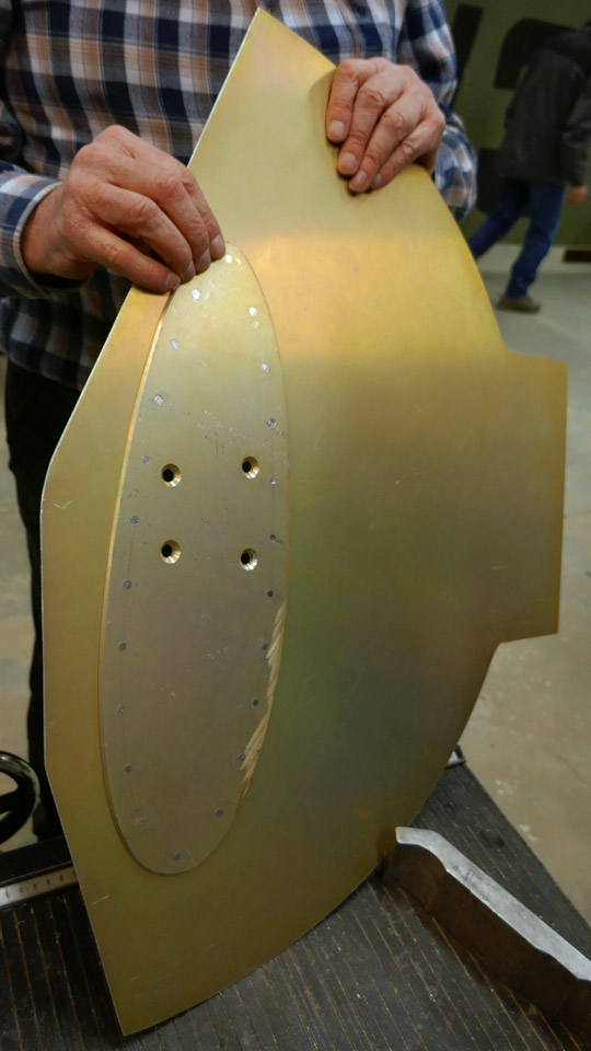
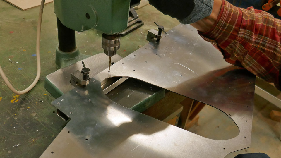
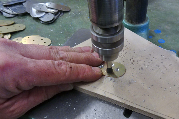
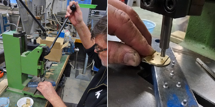
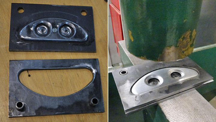
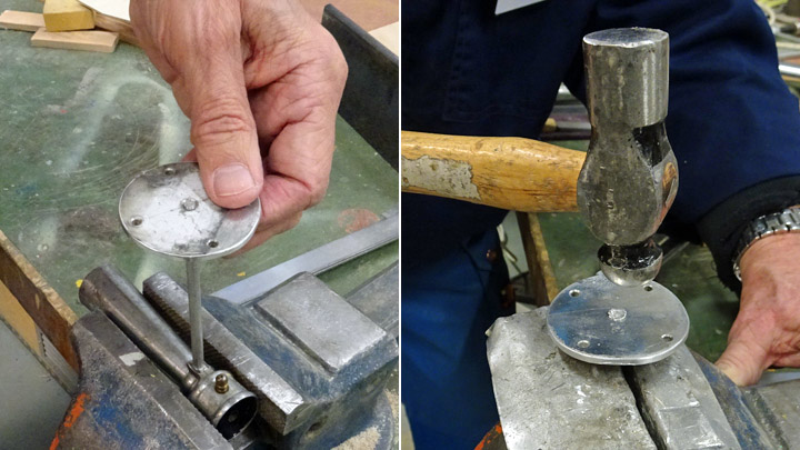
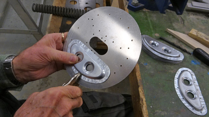
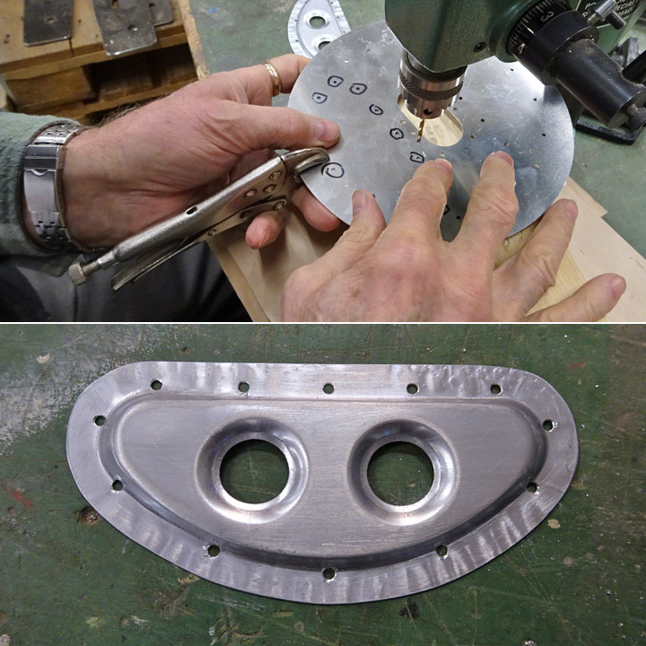
The oval stiffening plate on the outside of the outer door of the wheel well was fastened on the wheel hub with four machine screws. Then the places for the rivet holes were marked on the edges of the stiffening plate. The oval plate is fastened on the door with rivets. A prick was used for marking the location of the holes. A temporary screw was fastened to both ends of the oval plate so that the stiffening plate could be pressed tightly on the slightly convex door. The screws keep the stiffening plate in its place on the door while the rivet holes are being drilled.
The holes were drilled using a vertical drill and beveled with a beveling drill bit. Then the stiffening plate was riveted on the door, from the inside of the door, using a riveting gun.
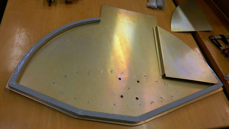
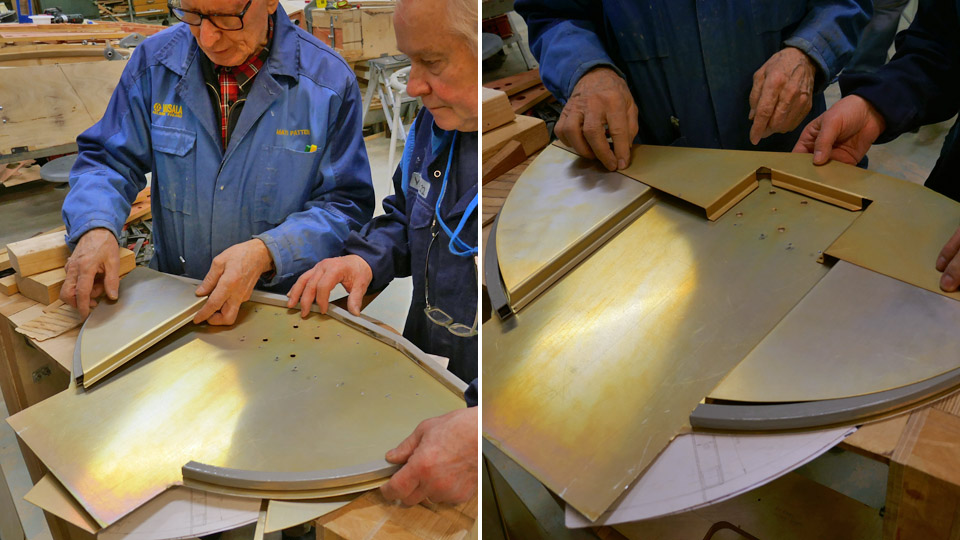
Then the box shaped stiffeners were preliminarily placed on the inner side of the outer wheel well door. There are stiffeners on both sides of the door and one at the bottom edge. The stiffeners are riveted by their outer edge on the supporting frame around the inner edge of the door, made of square steel tube, and by their hems on the door. The supporting frame of steel tube was not chromated but painted with grey Isotrol paint to prevent it from rust.
The riveting of the box-shaped stiffeners was not started before the Tuesday Club activities were terminated due to the Corona virus pandemic. The stiffeners were riveted on the oleo door but the stiffeners on the outer door of the wheel well are still under work. The landing gear of the test wing will have to wait until the work continues after the virus epidemic is over. Photos: Lassi Karivalo Translation: Erja Reinikainen |
|
Avainsanat: aviation history, restoring, old aircraft, VL Myrsky II, MY-14 |
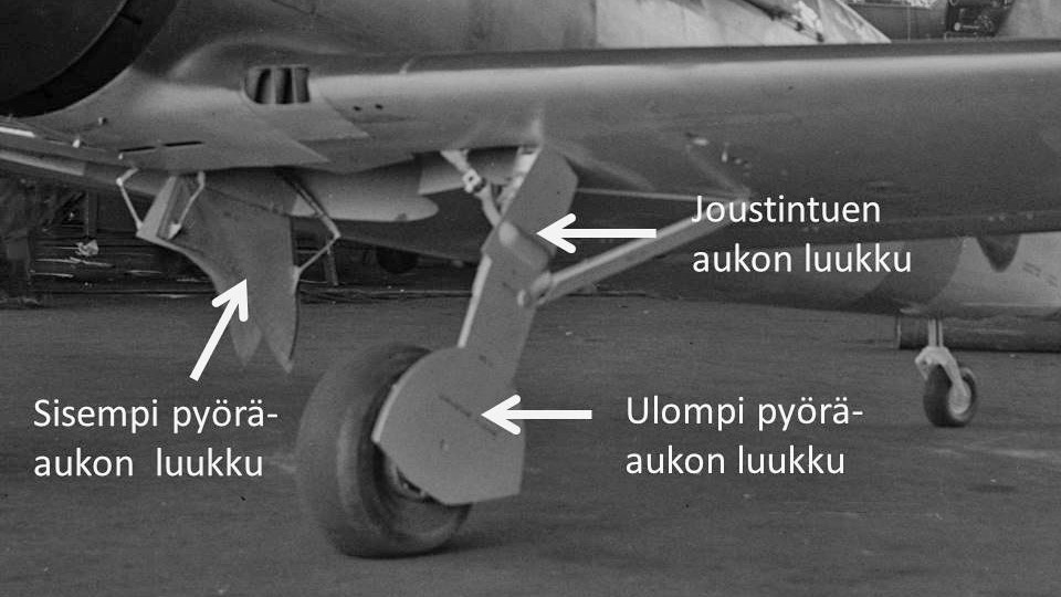
Wheel well and oleo doors for Myrsky are madeTiistai 7.4.2020 - Member of Tuesday Club Retractable landing gear was common already in WW2 fighters and VL Myrsky is not an exception. At the root of Myrsky’s wing there is an enclosure for pulling in the landing gear. The enclosure consists of a wheel well for the wheel and a compartment for the oleo (the shock strut of the landing gear). One half of the wheel well opening is covered by the inner door, made of aluminum plates, also called “daisy cutters”. The door is fastened on the inner edge of the wheel well with hinges. This door is opened automatically by a spring lever when the landing gear is taken out and it is closed by the wheel when the landing gear is taken in.
The other half of the wheel well is covered by the outer door, which is made of aluminum plate and fastened on the wheel hub, it is a pair for the “daisy cutter”. The oleo enclosure door is made of aluminum plate as well and it is fastened angel on the oleo. These two doors on the landing gear are overlapping at a distance of about 20 cm and they slide against each other when the landing gear oleo is flexing. The wheel is fastened by its axle on the “piston rod” which moves inside the oleo. The landing gear can’t have one solid door fastened on the wheel and oleo because this would disturb the vertical flexing movement of the wheel. The Tuesday Club team made first the inner doors for MY-14 wheel wells on the test wing and the actual wings. Then the construction of the outer doors and the oleo doors was started. The team decided to make the doors for the test wing first.
A laser cutter was used when cutting the semi-finished shape of the oleo door from 1.5 mm aluminum plate according to Myrsky’s original drawing. At the same time a hole was cut into the plate where the retraction mechanism fork connects to the oleo. Holes were drilled along the edges of the door where stiffening battens will be riveted.
A small canopy is needed to cover the hole where the retraction mechanism fork connects to the oleo. A metal mould was made first and the canopy was pressed against it from aluminum plate. The canopies were made for the test wing and for the actual wings. The canopy was welded onto the edges of the hole on the door. After this the pre-cut door was fitted into place into the oleo opening and fastened on the temporary plywood brackets on the oleo. Eventually the door will be riveted on the brackets which are welded onto the oleo.
The semi-finished shape of the outer wheel well door was also cut from 1.5 mm aluminum plate with a laser cutter. The door is fastened on the wheel hub with four 6 mm flat head machine screws. The holes on the door for the screws have to be exactly in the right position to meet the threaded holes on the wheel hub. The positioning was done by placing a positioning plate with sharp-pointed markers on the wheel hub. A marker was also placed in the middle of the hub. Then the door was positioned carefully into the wheel well and the plate surface was tapped against the marker points. Now there were clear marks on the lower side of the plate for drilling the holes for the screws. The marker marks were strengthened with a spike before making the holes with a vertical drilling machine.
The door fastened on the wheel hub has an oval-shaped stiffening plate on the outside. It was cut from aluminum plate. The stiffening plate is fastened on the door with the four machine screws which fasten the door on the wheel hub. Holes were made on the oval stiffening plate and the edges were beveled. The stiffening plate will also be riveted on the door by its edges. The outer wheel well door was fastened on the wheel hub with the oval stiffening plate attached. Now the test wing landing gear had both doors in place for the first time. They are well visible when the landing gear of the test wing is taken out.
There will be stiffeners and supporting battens on the inner surface of the outer door in the wheel well. A supporting frame made of rectangular steel tube will be fastened on the edge of the door. The lower part of the door will have box construction strengtheners made of aluminum plate.
Pre-cut strengtheners for the inner surface of the wheel well door were cut from aluminum plate with the laser. They were modified to be fitted and fastened into place. Also the stiffeners for the oleo door are now ready. The stiffeners will not be riveted on the doors before the half ready doors and the stiffeners have been chromated. The chromate treatment will prevent the aluminum plate from oxidizing and it will be done by an outside supplier. Photos: Lassi Karivalo Translation: Erja Reinikainen |
|
Avainsanat: aviation history, restoring, old aircraft, VL Myrsky II, MY-14 |
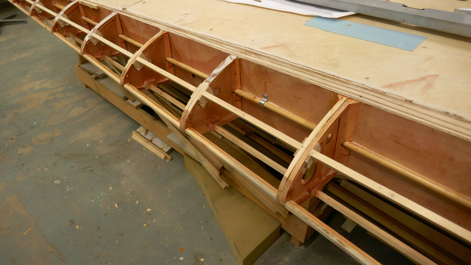
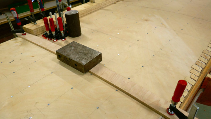
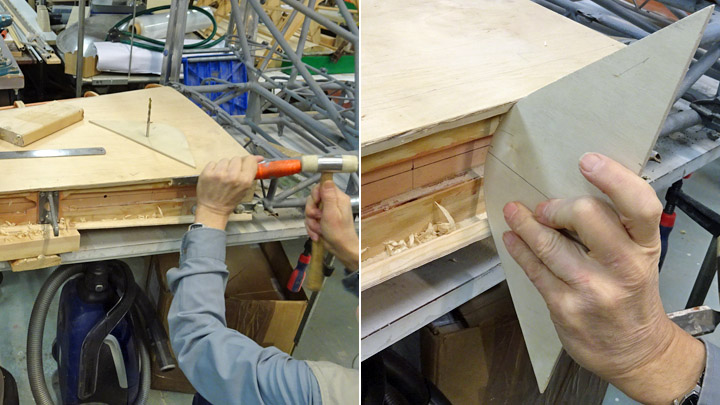
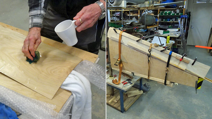
Experimenting dry plywood covering for leading edge on Myrsky's starboard wingTiistai 10.12.2019 - Member of Tuesday Club The restoration work of VL Myrsky II (MY-14) has progressed well during the autumn and the plywood covering on the starboard wing has been completed, excluding the leading edge. The plywood work on the leading edge has had to wait that the work on the port wing, which is being built alongside, reaches the point where the trailing edge is under construction. This is when the two wings under construction in the restoration space of the Finnish Aviation Museum change places. The wings will be moved from their first work platform on to the other platform. This is necessary in order to have enough working space around the wing to complete the port wing’s trailing edge and the starboard wing’s leading edge.
The leading edge of Myrsky’s wing consists of plywood ribs and supporting battens between the ribs. The leading edge is covered with 1,5 mm thick plywood. One sheet of plywood covers the surface of four rib-gaps. Four joining plywood sheets are needed to cover the whole leading edge, which is about five meters long. The plywood sheets are joined on a rib, using a scarf joint.
The challenge in the plywood covering of the leading edge is to bend the plywood sheet around the tapering leading edge. If the profile of the leading edge is very pointed, bending the dry plywood sheet around the edge will cause tears and cracks on the outer surface of the plywood. To prevent the plywood from cracking, the sheet is usually moistened or sometimes the wet plywood is fastened on a last, which models the leading edge. The plywood sheet will dry on the last and form a trough, which can be installed on the leading edge.
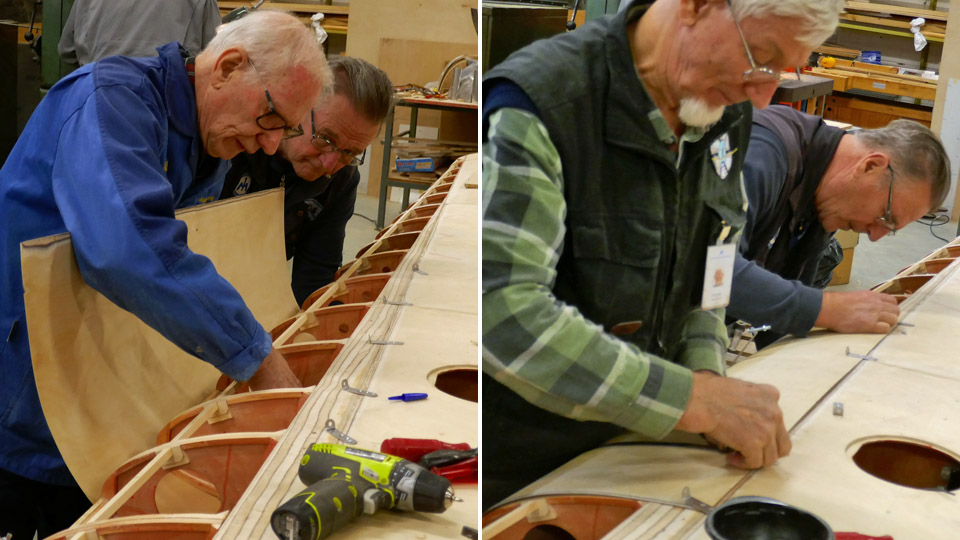
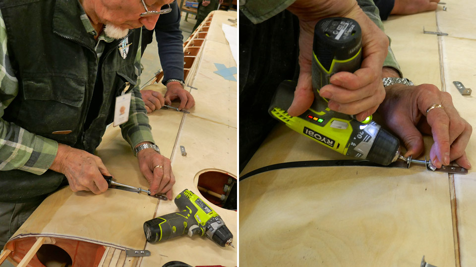
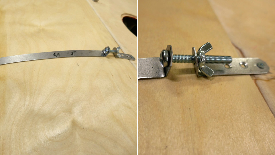
The Tuesday Club team wanted, however, to make an experiment and bend the dry thin 1.5 mm plywood sheet on the leading edge. The leading edge profile on Myrsky’s wing is not very pointed. For the experiment steel bands were made from 1 mm thick steel plate, they were cut 10 mm wide. The bands are used for pressing the plywood sheet evenly against the leading edge ribs. A steel band was made for each rib on the leading edge, corresponding the length of the leading edge profile. The bands were placed on each rib.
A tightening clamp was made at the upper end of each band, with a wing nut for tightening the band against the plywood. At the tightening clamp the ends of the band are bent to an angle of 90 degrees for the wing nut joint. The lower end of the band is fastened with a screw on the front spar on the lower side of the wing. The upper end of the band (with the tightening clamp) is fastened on the upper side of the wing on the wing spar.
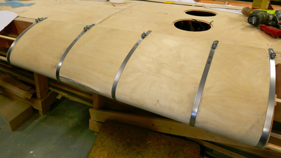
The dry bending of the plywood covering was experimented without any gluing along the distance of four rib-gaps. The bands were fastened on their places on the five ribs, with the tightening clamps still open. A piece of plywood was cut from the 1.5 mm thick plywood sheet, matching the area of the four rib-gaps. The edges of the plywood sheet were bevelled so that the adjacent sheet can be joined with a scarf joint.
When the preparations for the experiment had been made, the plywood sheet was fitted, lower edge first, between the leading edge ribs and the tightening bands so that it reached the front spar on the lower side of the wing. Then the plywood sheet was pressed against the ribs, using the bands. When the sheet was in place, the clamps were tightened with the wing nuts. Now the plywood sheet was tightly pressed against the ribs.
The Tuesday Club team was annoyed when a crack in the plywood veneer sheet was noticed at the tip of the leading edge. This means that the experiment failed: dry plywood can’t be used when covering the leading edge on Myrsky’s wing. The 1,5 mm thick plywood sheet has to be moistened on its outer surface before it is pressed and tightened with clamps against the leading edge ribs. Photos: Lassi Karivalo Translation: Erja Reinikainen. |
|
Avainsanat: aviation history, restoring, old aircraft, VL Myrsky II, MY-14 |
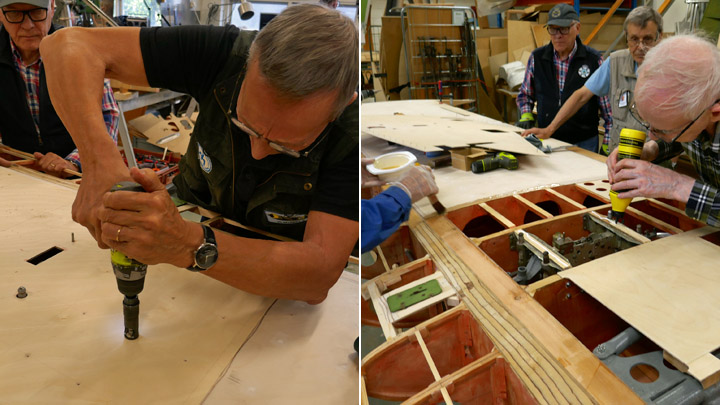
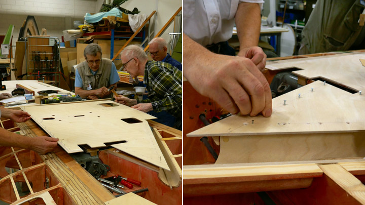
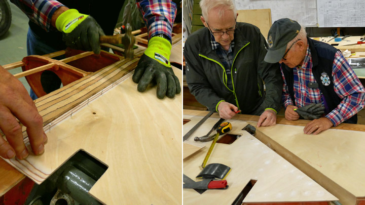
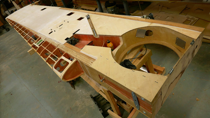
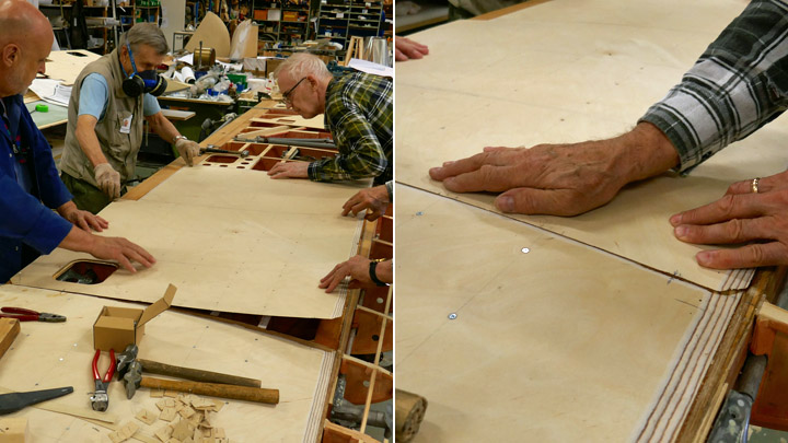
Plywood covering on the lower surface of Myrsky's port wing is readyTorstai 19.9.2019 - Member of Tuesday Club The covering of the lower surface of Myrsky’s (VL Myrsky, MY-14) port wing has been finished in the area between the wing spars. Three sheets of plywood have been installed, starting from the wingtip, and the area around the landing gear is ready as well. As the upper surface has earlier been covered with plywood, the following work phase will be the construction of the flap space on the trailing edge. Also, the leading edge in front of the front spar will be covered.
Pieces from 3 mm thick plywood sheet were cut diagonally to cover the remaining area of the wing. Several holes, large and small, were drilled into the plywood sheet which covers the area around the auxiliary fuel tank / bomb rack. The holes are needed for the equipment on the rack and as operation hatches. The small plywood sheets were shaped to match the shapes of the landing gear and wheel wells.
When the lower surface of the wing will be covered, as it was on the original Myrsky, the plywood will cover the structures of the wing and the equipment inside the wing (such as the auxiliary fuel tank / bomb rack and the operation mechanisms for the ailerons and landing gear). In a way it is a pity that the complicated wing structure and the interesting mechanisms will disappear from sight and the future museum visitors won’t be able to see them. Fortunately, the Myrsky’s test wing (a 2,5m long piece of the wing) has been built during the project and will be partly covered with transparent plexiglass. On the test wing the structures inside the wing, the landing gear, bomb rack and other equipment can be seen.
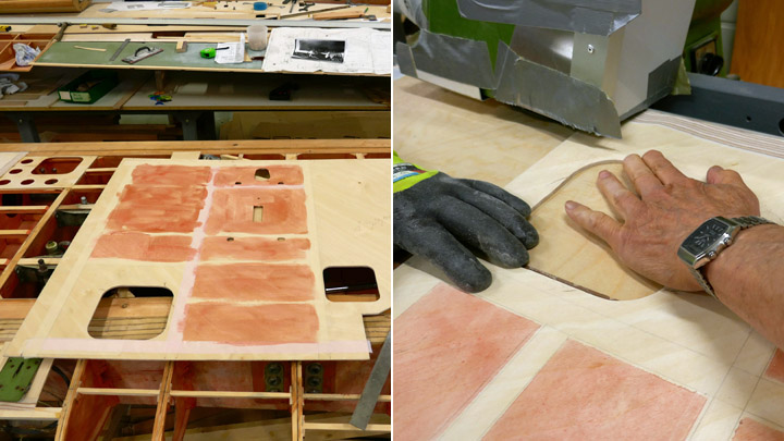
When the last sheets of plywood had been cut into shape and tested in place, the inner surfaces were painted using polyurethane lacquer tinted red. Then the edges of the plywood sheets were beveled for the lap joints.
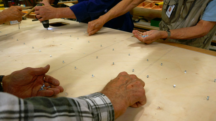
The plywood sheet in the bomb rack area was fastened first. Before gluing, the holes for the screws were drilled on the plywood sheets. Screws will be used to secure the glue joints. Flathead screws are used and the matching beveling was drilled on the plywood sheets. Then the glue was spread.
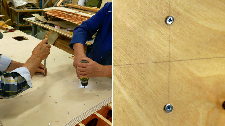
Epoxy glue was used when gluing the plywood sheets on the wing spars. Erikeeper Plus wood glue was used on the battens between the ribs. The sheet of plywood was pressed against the glued surfaces. The plywood sheet was secured in the right position, using a nail at each corner of the sheet.
When the screws had been fastened on the joints, the gluing on the front and rear spars was secured using 10 mm nails. Finally, a thick strip of plywood was placed on top of the lap joint of the plywood sheets.
When this sheet of plywood had been fastened, a couple of smaller plywood pieces were glued into place in the landing gear area. Now the lower surface of Myrsky’s port wing had been covered in the area between the spars. The wing looks like a wing now! Photos: Lassi Karivalo Translation: Erja Reinikainen |
|
Avainsanat: aviation history, restoring, old aircraft, VL Myrsky II, MY-14 |
Plywood covering on lower side of Myrsky's port wing is under wayTorstai 12.9.2019 - Member of Tuesday Club The covering of the lower side of Myrsky’s (MY-14) starboard wing was finished in early autumn and the work on the port wing could be started. The lower side between the wing spars will be covered with plywood. On the trailing edge side of the rear spar the aileron and flap will be assembled. The leading edge in front of the front spar will be covered later.
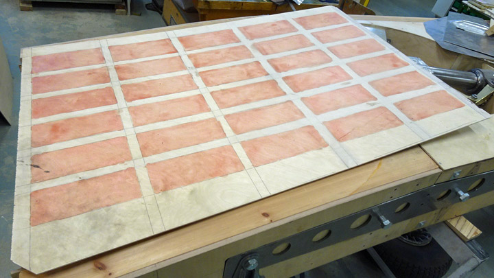
Pieces from 3 mm thick plywood sheet were cut diagonally to cover an area at the tip of the wing. These sheets are placed on the area between the spars to cover the area between 10 ribs, starting at the wingtip. One more sheet of plywood will be needed before the whole lower side of the wing is covered. The edges of the cut sheets were beveled for a lap joint and the lower side was protected against moisture using lacquer tinted red.
Screws will be used to make sure that the plywood is pressed tightly against the ribs and the supporting battens between the ribs. The holes for the screws were drilled on the plywood sheets. Three screws per batten between the ribs were used. Flathead screws are used and the matching beveling was drilled on the plywood sheets. Before gluing the correct positioning of the plywood sheets was ensured.
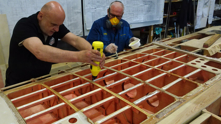
Epoxy glue and Erikeeper Plus glue was used when gluing the plywood sheets into place. Erikeeper Plus wood glue was used on the battens between the ribs.
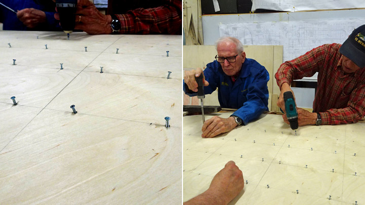
Then the screws were fastened. A screw was placed into each hole, then a cordless screwdriver was used to fasten them through the plywood into the battens between the ribs. The work was finalized using a manual screwdriver so that the screw heads were about one millimeter below the plywood surface. The indentations on the surface will be covered and coated later.
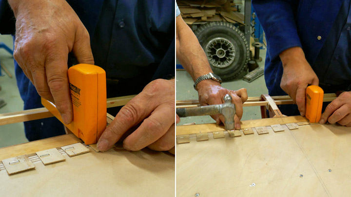
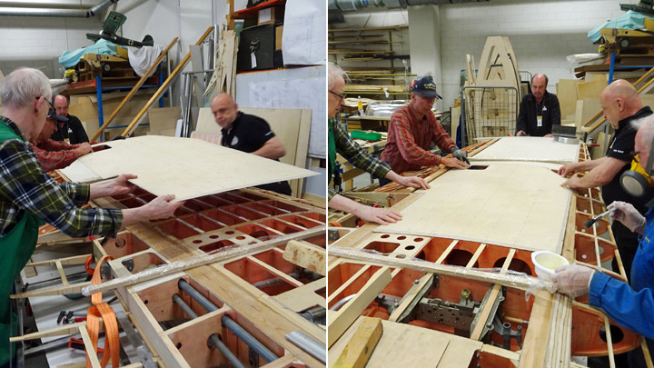
The gluing of the plywood sheet edges on the front and rear spar was not secured with screws but using staples. The staples were “shot” on the plywood through small protecting pieces of plywood so that the surface of the plywood is not damaged. The proper fastening of the staples was secured using a hammer. When the glue has dried the protecting pieces of plywood and staples will be removed.
Finally, a thick strip of plywood was placed on top of the lap joint of the plywood sheets. Clamps were used to secure the strip and a metal weight was placed on top of the strip. Now the lower surface of the port wing had been covered from the wing tip as far as the auxiliary fuel tank / bomb rack. The plywood sheet covering this area is already under work. Photos: Lassi Karivalo Translation: Erja Reinikainen. |
|
Avainsanat: aviation history, restoring, old aircraft, VL Myrsky II, MY-14 |
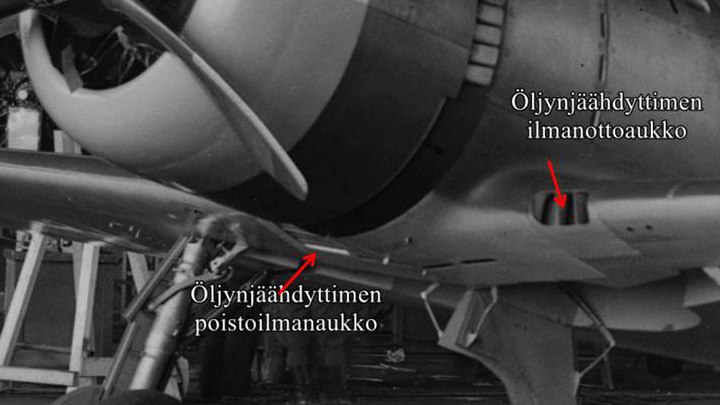
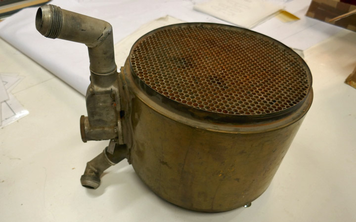
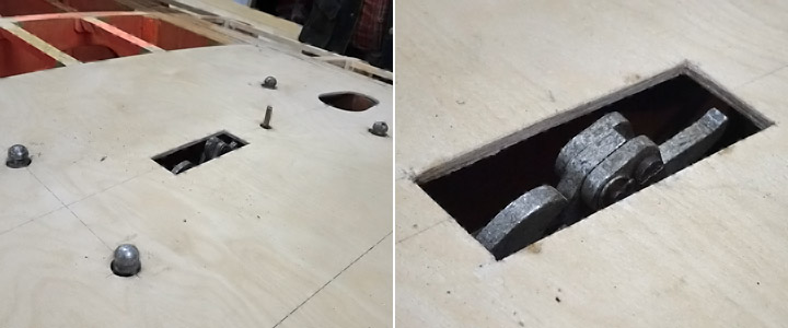
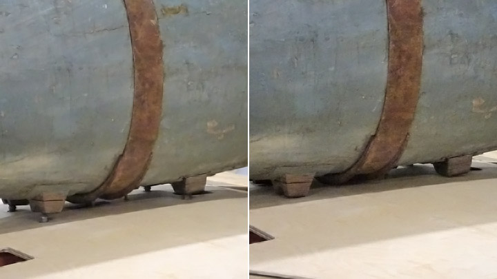
Ducts for Myrsky's oil cooler are builtLauantai 7.9.2019 - Member of Tuesday Club Myrsky’s Pratt & Whitney R-1830 Twin Wasp engine has a barrel-shaped oil cooler, similar to those on the DC-3 Twin Wasp engines. The motor oil is cooled, using air which flows through the cooler. At one end of the cooler there is a horn-shaped duct for supply air and at the other end a horn for exhaust air. Both ducts have a very complicated shape. The cooling supply air intake is at the leading edge of the port wing root. The exhaust air is lead out under the fuselage through an opening in the front fairing at the wing root.
(Öljynjäähdytin = Oil cooler, poistoilma-aukko = exhaust air vent, ilma-aukko = cooling air intake vent). The air flow to the oil cooler is controlled using the three parallel dampers inside the supply air duct. When all dampers are closed, they shut off the air flow to the cooler. By adjusting the dampers, the pilot can control the air flow to the oil cooler and the engine oil temperature.
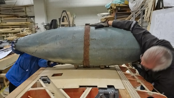
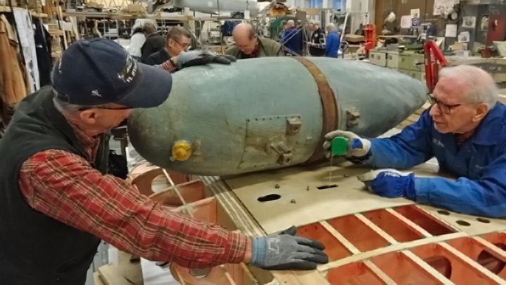
The Tuesday Club team was surprised to find an oil cooler for a Pratt & Whitney R-1830 Twin Wasp engine on the shelf of the working space in the Finnish Aviation Museum. The museum gave the oil cooler to be installed on the MY-14 engine, which was greatly appreciated. When an oil cooler was available, the work on the supply and exhaust air ducts could be started.
There are no original oil cooler ducts for Myrsky, so all parts will have to be reproduced. The work was started by building a part of the supply air duct which connects to the left end of the cooler. Myrsky’s original drawings were used to make a horn-shaped wooden last. One end of the last is round in diameter, matching the shape of the barrel-shaped oil cooler. The other end of the last is square is shape, matching the shape of the supply air duct’s other end.
First a sheet of cardboard was wrapped around the wooden last so that a cardboard pattern can be made and used to cut a suitable piece from 1 mm thick aluminum sheet. The appropriate piece of aluminum sheet was cut, and it was bent around the last with tightening straps. The aluminum sheet was bent to match the duct shape. When the semi-finished duct was unfastened from the last, its edges were fastened to each other with rivets. The final phase was to cut the ends of the duct to the right shape, matching the last, and honed smooth. The first part for the supply air duct was ready.
Another similar supply air duct part was made for the display object, which will be built around the fuselage frame of MY-5. A four-meter long test wing is being built during the restoration process and this test wing will be fastened on the MY-5 fuselage frame. The aim of this partly restored MY-5 is to illustrate what the inside of the Myrsky looks like. The fuselage frame will not be covered, and the test wing will be partly covered using transparent plexiglass.
While the supply air ducts for the oil cooler were being made, also the work on the control dampers was started. The leader of the Myrsky-project, Mr. Matti Patteri, programmed the shape of the dampers on a laser cutter, using original drawings. The dampers were laser cut at ProLaser Oy and they have been sent to the Tuesday Club and are waiting for further activities. Photos: Lassi Karivalo except historical photo: The Finnish Avitation Museum's photo archive. Translation from Finnish to English: Erja Reinikainen. |
|
Avainsanat: aviation history, restoring, old aircraft, VL Myrsky II, MY-14 |
Myrsky activities in JulyTiistai 23.7.2019 - Member of Tuesday Club The Tuesday Club members involved in the restoration work of Myrsky (MY-14) don’t want to stay away from the workshop, not even in July! They want to bring the restoration project forward even during the holiday season.
The team has concentrated on finishing the covering on the starboard wing’s lower side. Now all the inner structures and the equipment inside the wing have been covered with plywood. However, some minor details in the plywood covering are still under work.
When the lower side of the starboard wing is ready, the work will continue on the port wing. The upper side of the port wing has been already covered between the spars. The work on the port wing includes installing all operation mechanisms of the ailerons and landing gear inside the wing, fastening the trailing edge ribs on the rear spars and covering the flap cavity on the trailing edge with plywood. Simultaneously the covering work can be started on the lower side, in the area between the spars, starting at the wing tip. All this work has been done already on the starboard wing, so the team anticipates the work to progress smoothly.
The wing has not been the only Myrsky work item in July. The port and starboard horizontal stablilizers have been covered and the plywood covering seams have been buffed out. The vertical and horizontal stabilizers were fastened on an assembly jig in order to install the root fairings on the seams where the stabilizers meet. The original Myrsky tail root fairings can be used, and no reproduction is needed. However, the original tail root fairings have been slightly damaged, so they need to be straightened and repaired before assembly.
The original duraluminium elevators have also been repaired, because they have some fractures and some parts are missing. The elevators will be installed on the horizontal stabilizer when they have been repaired.
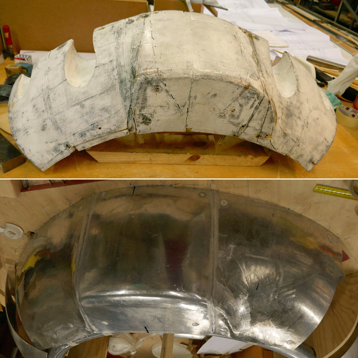
A wooden last was made to shape the Myrsky’s engine cover, ie. NACA ring. In July the last for the upper half of the NACA ring was sent to the company which will prepare the ring. The upper half consists of three aluminium plate segments welded together. The three parts were shaped against the last, using a lead whip. When the shape was correct, the segments were welded together to form the upper half of the NACA ring. The part came back to the Tuesday Club in mid-July. The upper half of the ring will have to be slightly modified and an opening for the engine air intake will have to be made before the upper half can be fastened on the rest of the NACA ring. Photos: Lassi Karivalo. Translation from Finnish to English: Erja Reinikainen. |
|
Avainsanat: aviation history, restoring, old aircraft, VL Myrsky II, MY-14 |
Flap niche on Myrsky's starboard wingSunnuntai 23.6.2019 - Member of Tuesday Club The assembly of Myrsky’s starboard wing has been going on for a couple of months. The ribs of the trailing edge have been installed up to the trailing edge strip. Also the operating mechanisms for the aileron, flap and landing gear have been installed through the holes in the ribs. At this point the Tuesday Club team could start covering the flap niche with plywood. When the flap is up / closed, it is pressed into this niche in the wing’s trailing edge. There is a notch in the trailing edge ribs, forming the perimeter of the niche.
The rest of Myrsky’s wing is a wooden structure but the flaps are split flap type plate flaps, made of duraluminium. When the flaps are up / closed and pressed into the niche under the wing, the flap is a part of the wing’s lower surface. When the flap is down / open, it turns down pushed by operation bars and angle gearboxes. The flap doesn’t move down and back as the flaps on modern passenger airplanes do.
The starboard wing’s flap cavity work was started by covering the front wall, 70 mm high, with 1.2 mm thick plywood. The next phase was the upper side of the niche which is as wide as the flap. Fortunately the starboard wing lay upside down, i.e. the lower side up. Fastening the plywood against the trailing edge ribs was much easier than it would have been if the wing were the right way up.
The flap niche will be covered with two sheets of plywood, connected in a lap joint. Two pieces of plywood were cut from 1,2 mm thick sheet of plywood, matching the dimensions of the niche. The joining edges of the sheets were beveled for the lap joint. The sheets were placed on the ribs, making sure that they settle properly against the ribs and the sides and can be glued into place.
When everything was ready, the plywood sheet towards the wingtip was glued first and then the sheet towards the wing root. Two-component epoxy glue with cellulose fibre was used. The glue was spread with a brush on the ribs, on the battens between the ribs, trailing edge batten and the front and end battens of the flap niche.
When the glue had been spread, the plywood sheets were pressed against the ribs and locked into place with aa couple of nails. Then heavy weights were placed on top of the sheets to press the glued surfaces together.
When the glue had dreid a triangular wooden batten was added to support the seam of the front wall and the roof plywood sheets.
Now the niche of the starboard flap had been covered. Photos: Lassi Karivalo. Translation from Finnish to English: Erja Reinikainen. |
|
Avainsanat: aviation history, restoring, old aircraft, VL Myrsky II, MY-14 |
Lover side of Myrsky's starboard wing is coveredTiistai 11.6.2019 - Member of Tuesday Club The Tuesday Club continues its work during the summer. The work concentrates on the covering of the starboard wing’s lower side between the wing spars. The wing tip has already been covered and one sheet of plywood towards the root of the wing. The covering work continued by gluing a third sheet of plywood in place. The covering of the whole lower side of the wing is possible when all the equipment and operation mechanisms inside the wing have been installed (such as the fastening and rejecting mechanisms of the auxiliary fuel tank). The upper side of the wing has already been covered earlier.
The original Myrsky wing plywood sheet had been cut from plywood board at a 45-degree angle, i.e. diagonally compared to the veneer layers. In ordinary thin plywood the bending strength and stiffness depend on the direction of the surface veneer, whereas diagonally cut plywood is equally stiff in both directions. However, cutting plywood sheets diagonally wastes material compared to cutting in the direction of the veneers. The restoration team decided to cut the plywood sheets diagonally for the Myrsky (MY-14), as they had originally been.
The work on the third sheet of plywood on the lower side of Myrsky’s starboard wing was started by placing a 3mm thick sheet of plywood on the wing area to be covered. The required piece was marked so that it can be cut diagonally. When the piece had been cut, its lower side was protected against moisture using lacquer tinted red. The areas to be glued were not lacquered.
Some finalizing work was needed before gluing the plywood. The supporting battens between the wing spars were honed exactly into the same level so that there won’t be any dents or bumps in the plywood surface. Holes were drilled into the plywood so that the gluing can be secured with screws on the supporting battens on the wing surface.
When all the preparations had been made, glue was spread on the front and rear spars, on the ribs and on the battens between the ribs. Epoxy glue with additional cellulose fibers was used on the spars and Erikeeper Plus wood glue on the ribs and battens.
The sheet of plywood was lifted above the wing and pressed against the glue. The correct position was checked and then the plywood sheet was secured in place, using a nail at the corner of the sheet. The screws were added to fasten the plywood sheet on the battens between the ribs. A cordless screwdriver was used, but the work was finalized using a manual screwdriver.
Cargo straps and strips of wood were used to press the plywood against the glued surfaces. Also clamps and metal weights were used to make sure that the edges of the plywood sheet press tightly against the glued surfaces. Now the third sheet of plywood on the starboard wing had been installed. Photos: Lassi Karivalo. Translation from Finnish to English: Erja Reinikainen. |
|
Avainsanat: aviation history, restoring, old aircraft, VL Myrsky II, MY-14 |
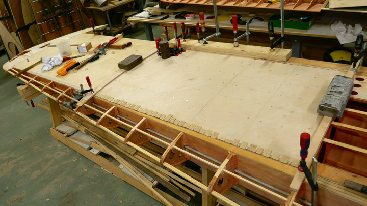
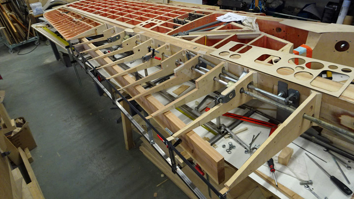
Assembly of Myrsky's wing ribs on trailing edgeTorstai 11.4.2019 - Member of Tuesday Club The preparation of ribs for Myrsky’s wings was started in the very beginning of the Myrsky restoration project in 2016. At the time ribs were made for the mid-wing section (between the wing spars) and for the leading and trailing edges.
Now the Myrsky wing restoration and assembly has reached the point where only the ribs on the wings’ trailing edge are missing.
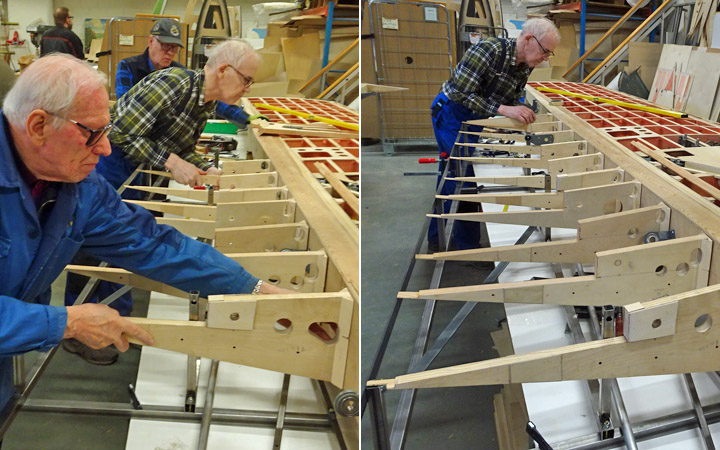
Both wings have 12 ribs on the trailing edge between the root of the wing and the aileron gap. Each rib has a notch for the flap on the lower side of the trailing edge. There are also holes in the ribs for the operating mechanisms of the ailerons and landing gear. For the installation of the trailing edge ribs the wing was placed upside down. This way it is easier to install the operation mechanisms for the ailerons and landing gear through the holes in the ribs. Furthermore, it is easier to make sure that the flap fits into the notch in the ribs.
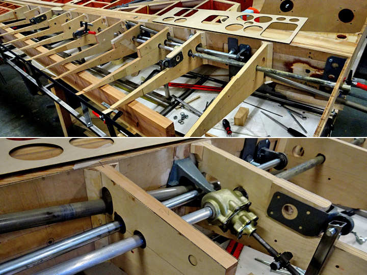
As preliminary work the bearing block, operation bars and angle gear box for the flaps and ailerons have been installed. Also the operation mechanism for the landing gear, which penetrates the ribs, had been tested in its place.
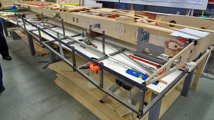
The most important preparatory work item was to build the assembly jig from steel tubes. It is necessary to use the jig to be able to place the ribs on the trailing edge in the right position. They must be exactly on the same level with each other and with the rear spar and the batten on the trailing edge.
The assembly work was started on the right / starboard wing. When the assembly jig was in place, the ribs could be placed one by one between the rear spar and the rear tube of the jig. At this phase the ribs were only preliminarily fastened.
When all the ribs on the trailing edge had been placed in a neat row between the rear spar and the rear tube of the jig, the operation mechanisms of the flap, aileron and landing gear were pushed through the holes in the ribs. At first glimpse the several operation bars and mechanisms are a jumble, but each bar and tube has a purpose and has its own route through the ribs.
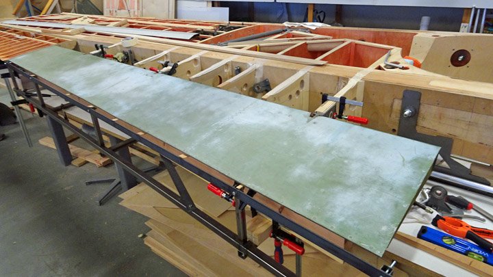
It was also tested how the flap settles into the notch in the ribs. The original aluminum flap pressed nicely into the notch and it also opened as expected.
The ribs will be glued onto the rear spar when the trailing edge batten which joins the tips of the ribs is ready and has been assembled into the jig. Translated from Finnish to English by Erja Reinikainen. |
|
Avainsanat: aviation history, restoring, old aircraft, VL Myrsky II, MY-14 |
Myrsky horizontal stabilizer is covered with plywoodMaanantai 8.4.2019 - Member of Tuesday Club The rebuilding of the Myrsky (MY-14) horizontal stabilizer is a good example how the restoring work progresses in phases. The phasing of restoring work is due to the prioritization of the various restoration projects. The rebuilding of Myrsky’s horizontal stabilizer has been going on whenever there has been a break in other Myrsky work, e.g. building the wings.
The frames of the horizontal stabilizer halves were finished already at the end of 2016 and then a 12-month break in the work followed. In 2018 the work was continued, and the halves of the horizontal stabilizer were covered with 1,5 mm plywood between the front and rear spars. Before the plywood covering was installed, the inner structures of the horizontal stabilizer halves and the inside surfaces of the plywood were varnished with polyurethane varnish, tinted red.
In the beginning of this year the covering of the leading and trailing edges of the horizontal stabilizer was started. The work was started at the trailing edge, where the hinge brackets for the elevator had been fastened. The trailing edge of the horizontal stabilizer is concave in shape to match the elevator’s leading edge which is hemispheric.
The covering of the trailing edge was started by carving the rectangular wooden battens on the upper and lower edge pointed, so that the trailing edge is curved inwards. As the work progressed, the shape of the trailing edge was checked regularly using a gauge to make sure that the concave shape is correct.
When the battens on the upper and lower edges had been carved, the halves of the horizontal stabilizer were fastened on an assembly jig, trailing edge upwards.
The covering work was started by cutting a thin strip of 1,5 mm plywood, matching the length of the trailing edge. Before the strip could be fastened, several supporting pieces of plywood (shaped to match the shape of the trailing edge) were glued on the trailing edge, using Casco Outdoor wood glue.
Then the plywood strip could be glued on the trailing edge. Epoxy glue was spread on the upper and lower surface of the trailing edge, on the end pieces and on the supporting plywood pieces. The plywood strip was forced against the concave trailing edge using a thick round wooden pole. The pole was fastened on the horizontal stabilizer using cargo straps. When the glue had dried the straps were removed and the additional skirts of the plywood were cut off. Both halves of the horizontal stabilizer were covered in a similar way. The halves were turned around in the assembly jig and the work on the leading edges could be started.
Pieces of 1,5 mm plywood were cut for the leading edge on both stabilizer halves. On the leading edge the covering piece of plywood stretches around the edge from front spar to front spar. The piece of plywood had to be shaped like a trough to match the profile of the leading edge.
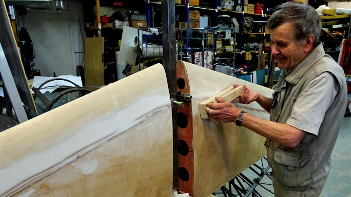
First the plywood was moistened with water. Then the damp plywood was pressed tightly around the leading edge of the horizontal stabilizer and fastened using supporting battens and cargo straps. In a couple of days the plywood had dried and the straps could be removed. The Tuesday Club team was pleased to see that the plywood now had the correct trough shape and matched the shape the leading edge. An alternative work method would have been to use hot steam to moisten the plywood and then fasten it on a mold.
Before gluing the plywood, it was test assembled around the leading edge. The team wanted to make sure that the plywood trough pressed tightly on the tip batten and on the leading edge ribs and reached on both sides as far as the front spar. The plywood covering of the mid-section of the horizontal stabilizer had been glued in an earlier work phase on the front spar. The leading edge covering meets this mid-section plywood with a scarf joint.
When the leading edge plywood covering was in place, the epoxy glue was mixed and cellulose fibre was added as binder. The glue was spread with a brush on the leading edge batten, ribs and the edge of the mid-section plywood on the front spar. The trough shaped plywood covering was pressed against the leading edge and fastened tightly using supporting battens and cargo straps.
The scarf joint of the two pieces of plywood connecting on the front spar was secured with staples from a stapling gun.
After a couple of days the cargo straps were removed. The team members knocked on the leading edge plywood to make sure that it had been properly fastened on the leading edge batten and the ribs. The staples securing the scarf joint on the front spar could be removed.
When the seams of the scarf joint had been ground smooth, the work was ready. Both halves of the horizontal stabilizer were covered in a similar way. Photos: Lassi Karivalo Translation from Finnish to English: Erja Reinikainen. |
|
Avainsanat: aviation history, restoring, old aircraft, VL Myrsky II, MY-14 |
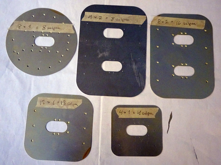
Making access panel latches for Myrsky's wingsMaanantai 4.3.2019 - Member of Tuesday Club There are dozens of access, maintenance and operation panels on the wing of Myrsky. The panels are of five different sizes.
The restoration project team has some original Myrsky wing access panels, but majority of the panels will have to be made. There is a latch in the middle of each access panel to open and close the panel. The “seesaw type” latch has a hinge in the middle and the latch is opened and closed by pushing it with a finger.
Because each access panel on the wing has one or two latches, more than 70 latches are needed on the two wings of the Myrsky and on the test wing. The restoration team decided to make all the identical latches in a serial process.
The frame of the latch is made of two aluminum plates which are riveted together. The access, maintenance and operation panels had been cut from 1 mm aluminum plate, using a laser cutter. This work method was used also to cut the latch frames. Holes for the rivets were also made. The rivets are 2,5x3,5 mm aluminum rivets with countersunk heads. Folds were made on the plate on the inside of the latch, the folds are needed for the hinge and the locking wire.
The first phase in the making of the latch frame was to make the holes for the rivets on the outer plate of the latch so that the head of the rivet will be on the level of the plate surface. The holes were made with a special drill piece on a vertical drilling machine.
The frame of the latch was made by riveting the inner and outer plates together. A powerful manual riveting tool was used. The inner and outer plates were put on the riveting table with the inner surface on top. Rivets were placed into the holes and then the rivets were pushed into place using the riveting tool.
Each latch frame has six rivets so the tool had to be used several times before the required number of latch frames were ready for further processing. Photos: Lassi Karivalo Translation: Erja Reinikainen |
|
Avainsanat: aviation history, restoring, old aircraft, VL Myrsky II, MY-14 |
Leading edge of Myrsky wing is assembledKeskiviikko 20.2.2019 - Member of Tuesday Club The Tuesday Club team has been working on the restoration of VL Myrsky’s wings. The work has progressed to the phase when the ribs on the leading edge of the wing can be installed. Previously the ribs have been prepared for the assembly and the tube for the electrical cable of the navigation light has been fastened on the front spar.
The ribs for the leading edge of Myrsky’s wings were made about a year ago. Triangular wooden battens were fastened on the root of each rib so that they can be glued onto the front spar. This arrangement makes the gluing surface wider on the rib root. Before gluing the ribs into place their sides were protected against humidity using polyurethane varnish, tinted red.
The aluminum tube for the electrical cable of the navigation light on the wingtip was installed before the ribs were installed. The aluminum tube was fastened in the middle of the front spar side facing the leading edge. Aluminum clips were used for fastening the tube on the spar. A notch for the tube had to be carved on the root of each rib before the ribs could be glued onto the front spar.
It is important that all the ribs are glued onto the front spar so that their tips are fully in line. If they are not, this will cause problems when covering the leading edge with plywood. A long metal bubble level was the perfect tool for making sure that the rib tips are in line.
The level showed that the ribs had slightly different lengths, a couple of millimeters. To compensate the error, thin strips of plywood were glued on the root of the shorter ribs. Several ribs had to be modified to make them slightly longer so that the tips met the level. When all the rib tips were in the correct position, a thin connecting wooden batten (8x8 mm) was pushed through the hole at the tip of each rib. When the batten was in place, the ribs were glued onto the front spar and secured into place with clamps.
When the glue had dried, the installation of the supporting battens between the ribs could be started. The battens are installed on the ribs on the upper and lower side of the wing, covering the full length of the wing. Strips of plywood were glued on both sides of each rib, at the lower edge. Then the supporting battens were glued onto the strips.
The battens on the upper side of the ribs will be installed when the wing has been turned around. Another supporting batten was added on the front side of the batten which penetrates the tips of the ribs. Now the tip batten became thicker and the front edge of the batten is at the level of the rib tip. The ribs were installed in a similar way on the leading edge of Myrsky’s both wings. Photos: Lassi Karivalo Translation: Erja Reinikainen |
|
Avainsanat: aviation history, restoring, old aircraft, VL Myrsky II, MY-14 |
Rack for auxiliary fuel tank of Myrsky is testedMaanantai 14.1.2019 - Member of Tuesday Club The VL Myrsky fighter has inside both wings a rack for fastening an auxiliary fuel tank or a bomb. The Tuesday Club team had several original parts of the rack for the Myrsky restoration work. The rack parts were repaired and cleaned and assembled together to form the racks on both wings of the Myrsky and also for the short wing built for test purposes. The rack on the test wing has been already tested.
The racks had been installed on both wings on the Myrsky. The area around the rack had also been preliminarily covered with new plywood so that the rack could be tested. Holes were made into the plywood covering for the rack mounting locator pins and the catch, which the auxiliary fuel tank or the bomb is locked on. Another hole was made for the indication pin, which forwards the information to the pilot when the auxiliary fuel tank or bomb has been released.
The testing of the rack could be done easily as the wings are on the assembly jig with the lower side upwards. For the test procedure the team could use an original Myrsky auxiliary fuel tank - fortunately a bomb wasn’t needed for the testing! The team decided to test the rack on the starboard (right) wing.
The auxiliary fuel tank was lifted upside down on the wing, which was upside down on the assembly jig. The tank was placed above the rack so that the four wooden steering blocks met the mounting locator pins, which penetrated the wing covering. The lock ring on the surface of the auxiliary fuel tank slid through the hole on the wing covering towards the lock catch on the rack.
The team was annoyed to discover that the fuel tank didn’t lock on the rack. When the tank was lifted and the distance of the lock catch from the wing surface was measured, the team noticed that the rack, placed inside wing between two wing ribs, was located about 5 mm too deep. The lock ring of the auxiliary fuel tank didn’t reach the lock catch. Although the rack had been installed according to the measurements on the drawings, this was what the situation was.
The team sighed and continued working, dismantled the rack and installed it again, this time 5mm closer to the surface of the wing. The auxiliary fuel tank was tested again on its place, this time it locked perfectly on the lock catch of the rack. Photos: Lassi Karivalo Translation: Erja Reinikainen |
|
Avainsanat: aviation history, restoring, old aircraft, VL Myrsky II, MY-14 |
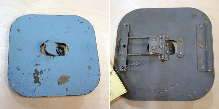
Hatch for Myrsky auxiliary fuel tank rack is being madeLauantai 8.12.2018 - Member of Tuesday Club There are several different inspection, maintenance and operation hatches on the wing of VL Myrsky II. There are four hatches for the auxiliary fuel tank racks which also served as bomb racks, two on either side. The hatches are made of 1 mm aluminium sheet. They are round and 17,5 cm in diameter. In the middle of each hatch there is an elongated lock disk, which has a spring and can be pushed open and closed using a finger.
The operation hatches of the auxiliary fuel tank rack have a complicated structure. Fortunately, the Tuesday Club team had a detailed original construction drawing for making the hatches. The drawing has been dated in November 1944, so it is from the time when the Myrsky planes were in production. Also one original auxiliary fuel tank rack hatch had been found. Other original hatches are not available.
The drawing on the auxiliary fuel tank rack hatch illustrates well how detailed drawings have been made even of the smallest parts when the Myrsky was designed. The drawing describes in detail the construction of the hatch and its parts, 12 of them in total. 42 rivets are needed when the parts are assembled together.
When the team started making the hatches for the Myrsky wings, billets for all the different hatches were cut from 1 mm aluminium sheet. Some of the hatches are round, some rectangular. A laser cutter was used for cutting the hatches. The exact shape and size of each hatch was programmed for the laser cutter and the data was fed into the cutter using a memory stick. The holes for the rivets were also cut using the laser, several rivets are needed to fasten the parts together. The advantage of the laser cutter is that the outcome is exactly according to the original drawing.
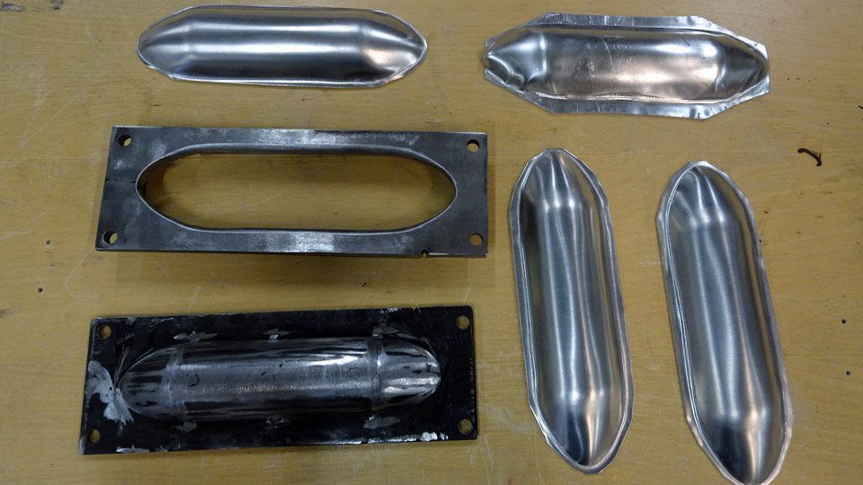
The first task of the team was to make the hatches for the auxiliary fuel tank and bomb racks. Six hatches are needed, two for each side and two for the Myrsky test wing. The first item to be made were the crescent-shaped stiffeners on the inside of the hatch. Twelve billets, slightly larger than the final stiffeners, were cut from 1 mm aluminium sheet. Two holes were cut according to the original drawing for making the stiffener lighter. For pressing the billets into shape, female and male pressing moulds were made. The billets were pressed into shape between the moulds.
The extra “skirt” was cut off.
The following task was to drill rivet holes on the edges of the crescent-shaped plates, so that they could be riveted on the inside of the hatch. The stiffener was clamped tightly on the inside of the hatch plate, exactly on the right place. Then the hatch plate was turned around and the rivet holes for fastening the stiffener, already laser cut on the hatch, were marked using a marker pen.
The holes were drilled along the edge of the stiffener. Soon all 12 stiffeners were ready to be fastened on the hatch plates.
Another Tuesday Club team was working on the lock disks which will be placed in the middle of the auxiliary fuel tank hatch. The parts of the lock disk were riveted together and the lock disk was preliminarily placed into the opening in the middle of the hatch. A lot of work will be needed before the six auxiliary fuel tank hatches are ready, not to mention all the other hatches, which are at the billet stage. |
|
Avainsanat: aviation history, restoring, old aircraft, VL Myrsky II, MY-14 |
Ilmailumuseot.fi - Aviationmuseums.fi