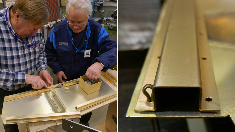
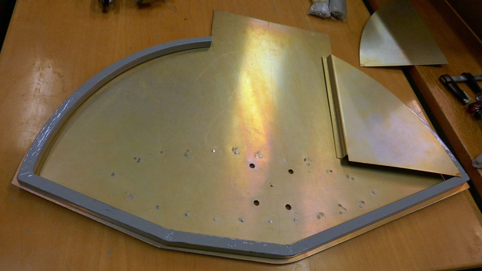
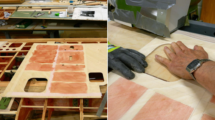
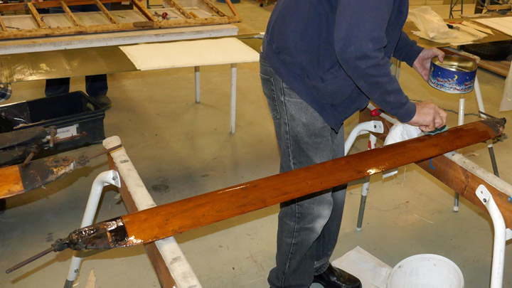
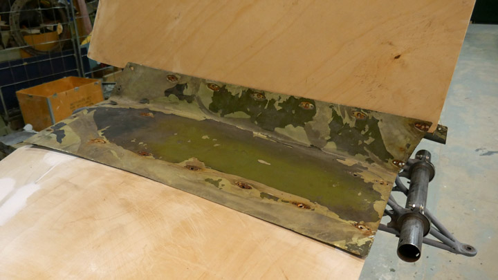
Stiffeners are fastened on Myrsky?s wheel and oleo compartment doorsTiistai 14.4.2020 - Member of Tuesday Club The VL Myrsky (MY-14) is being restored and its parts around the wheel well, including the outer door of the wheel well, the door of the oleo compartment and the door stiffeners were sent to be chromated. When they came back from the chromating process, it was time to fasten the stiffeners on the doors. Chromate bathing means that the aluminum plate is treated with acid solutions containing chromates and a thin inorganic film is formed on the surface of the aluminum with the components of the surfacing bath liquid. This surfacing protects the aluminum plate from oxidization. In the chromate process the Myrsky’s landing gear doors and their parts got a beautiful golden hue on the surface.
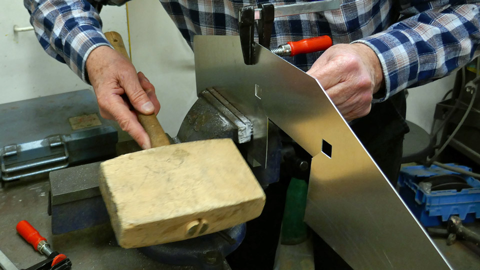
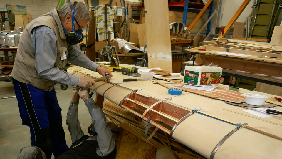
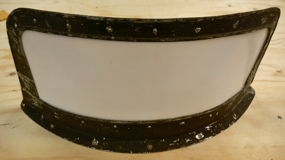
First the stiffening battens were fastened on the landing gear oleo compartment door. The battens have top hat profile. This means that the square batten is open at the bottom and it has sleeves bent to the sides. The sleeves have holes for riveting the stiffening batten on the edges of the door.
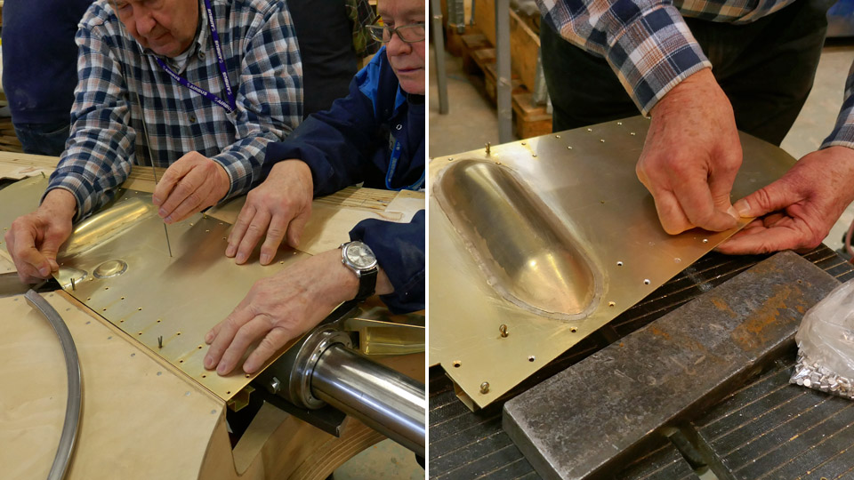
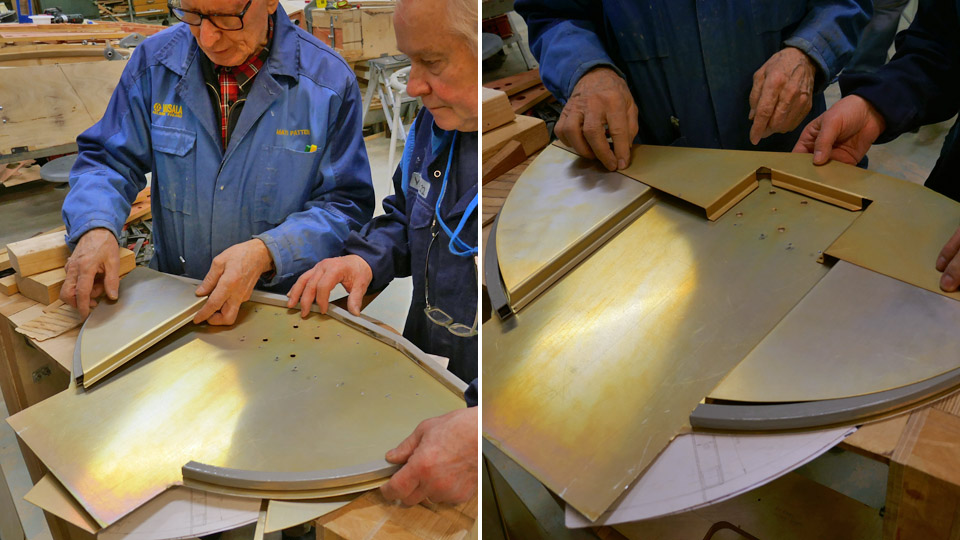
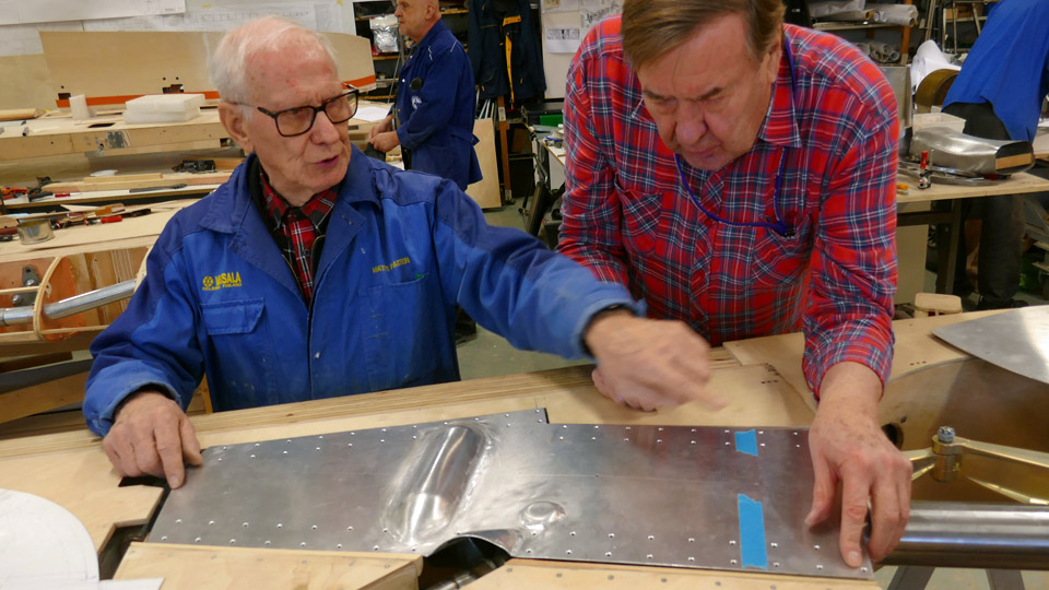
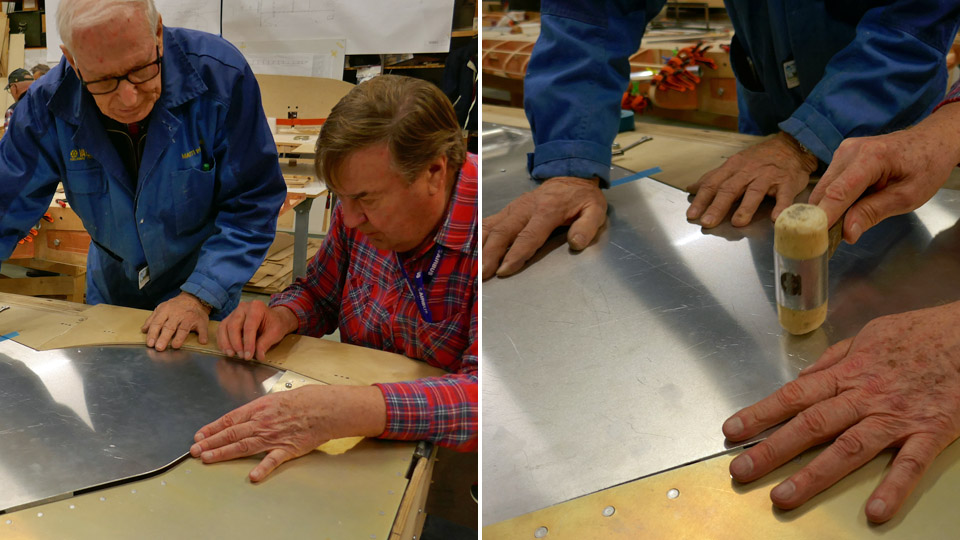
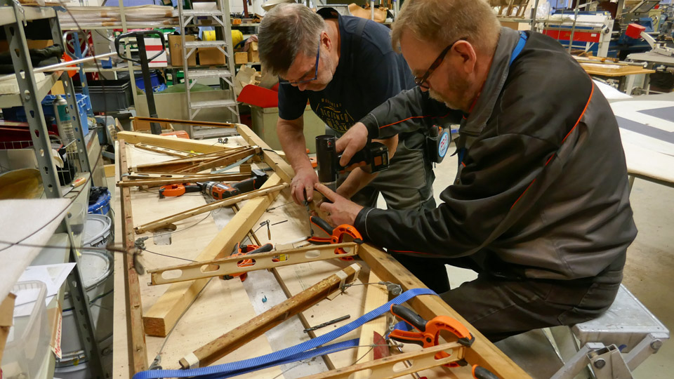
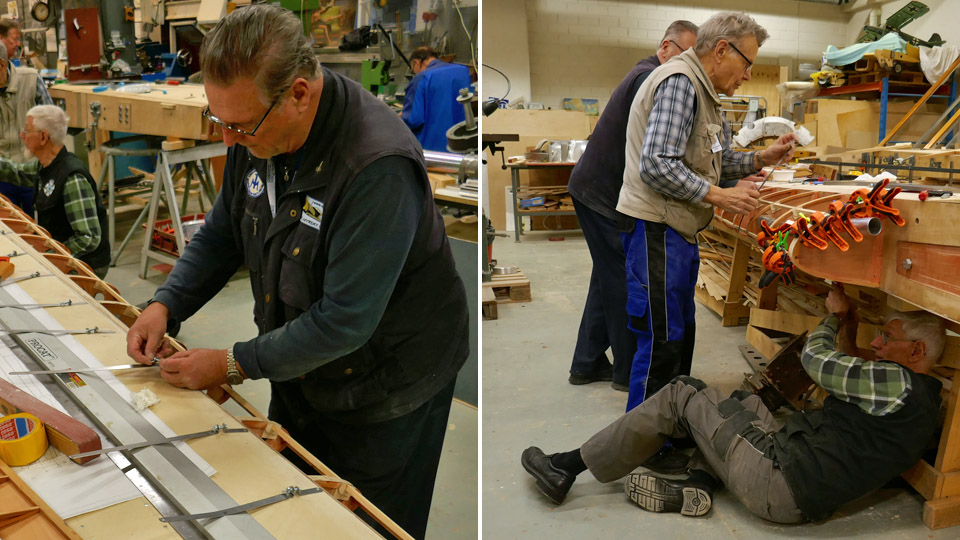
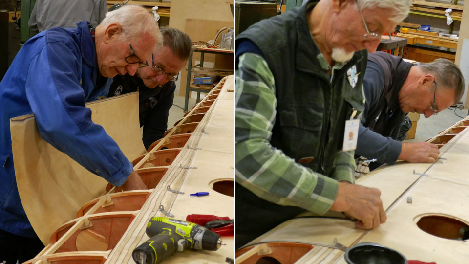
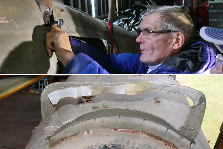
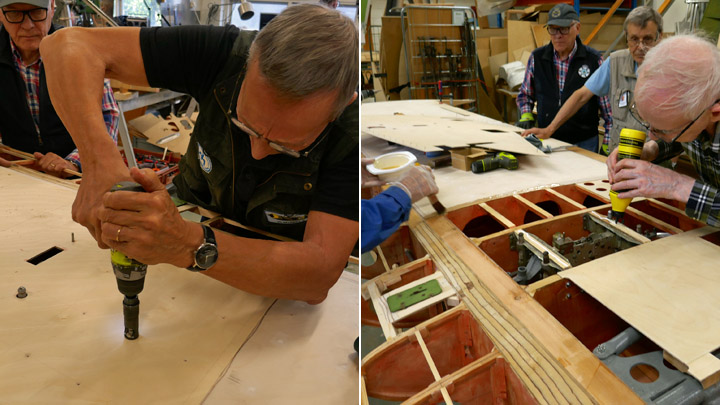
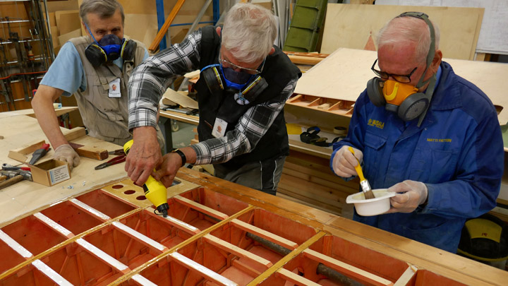
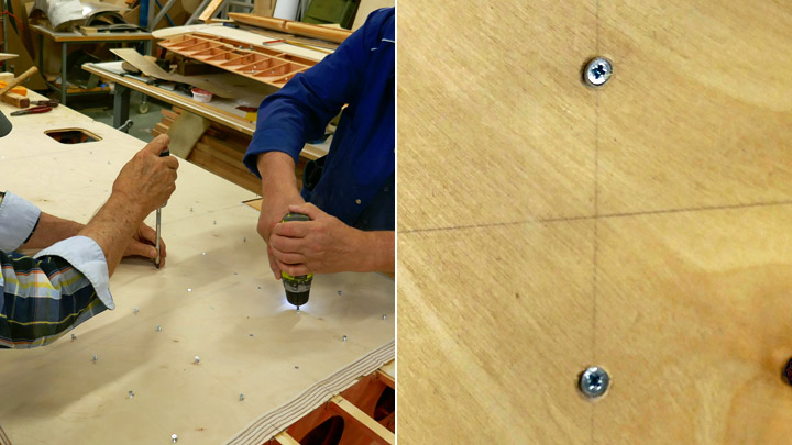
The holes for the rivets had already been drilled earlier on the oleo compartment door and on the stiffening battens. The rivet holes on the edges of the door had also been beveled for flat head rivets. The stiffening battens were riveted on the lower side of the door. The work was started by fastening the battens into place with a couple of pins which were pushed through the rivet holes. Before riveting the battens the oleo compartment door was assembled into place and the team made sure that it fitted properly in its place also with the stiffening battens.
Then the battens were riveted on to the inner side of the door, rivet by rivet, using the riveting gun. The riveting gun is faster and more practical than using a hammer for the riveting work. When all the stiffening battens had been fastened on the oleo compartment door, the work on the stiffeners for the door on the wheel hub was started.
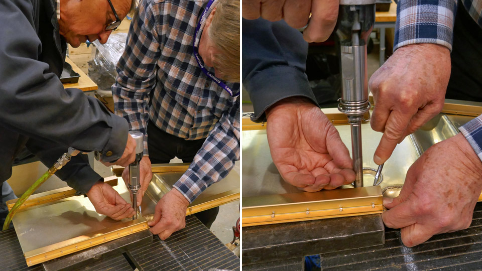
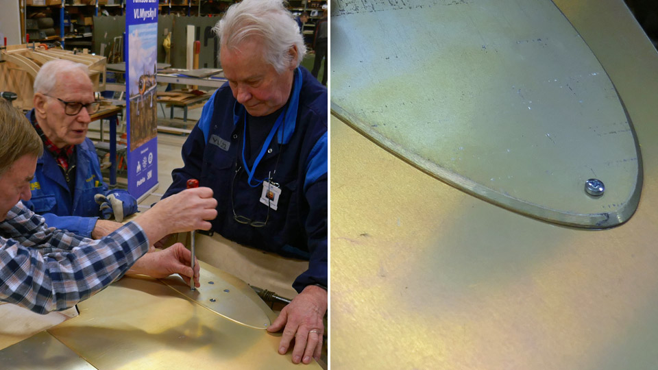
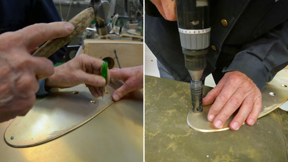
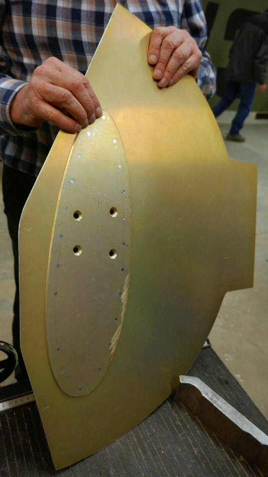
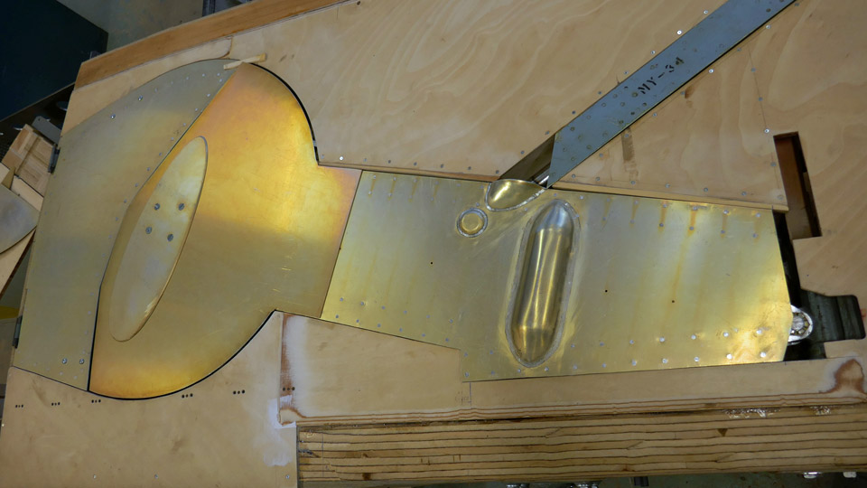
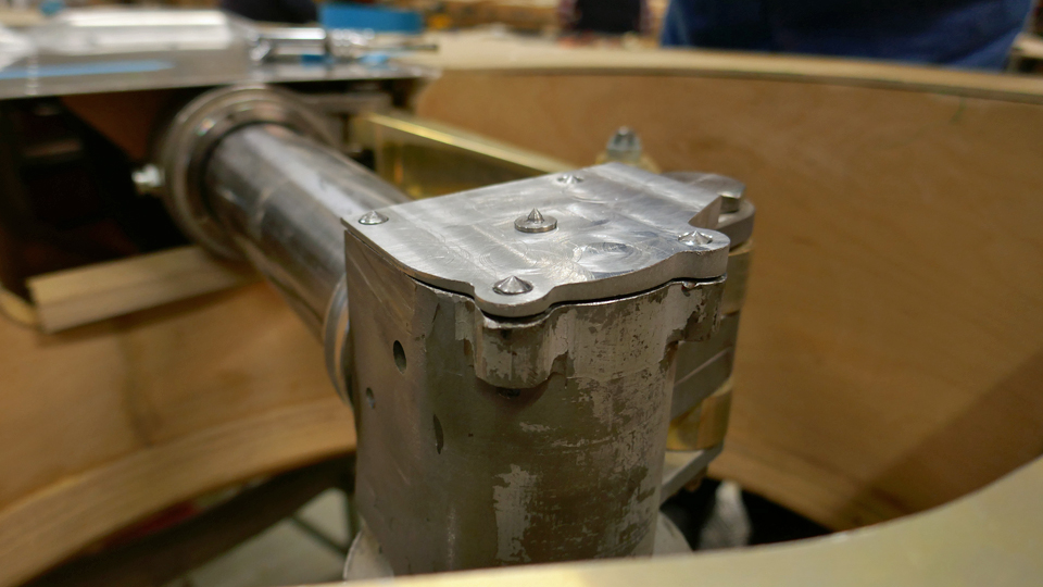
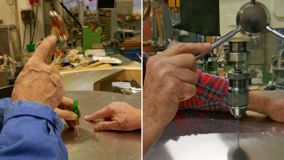
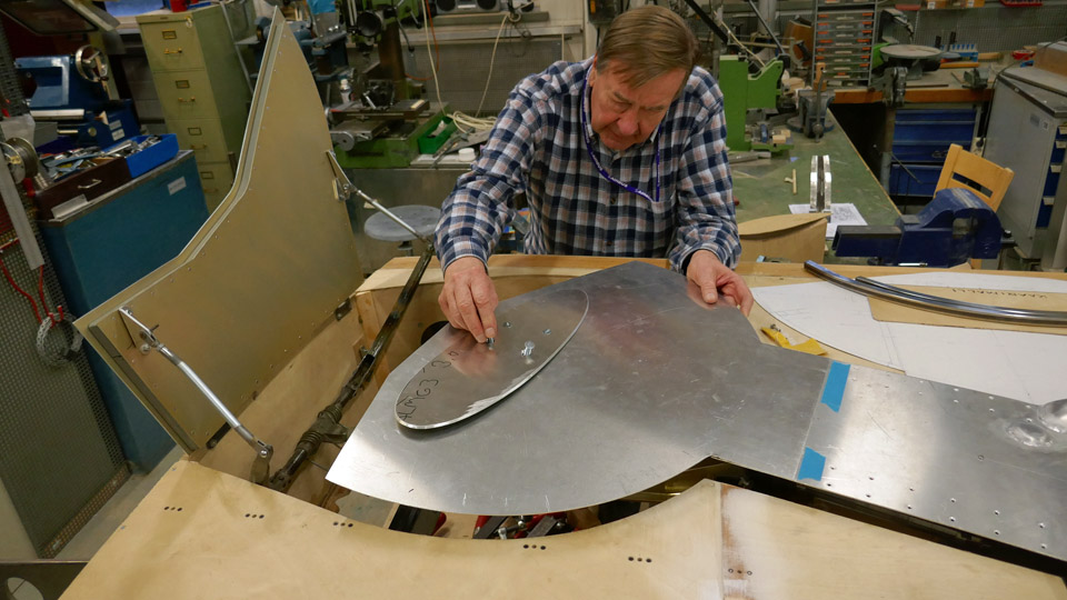
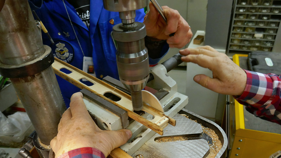
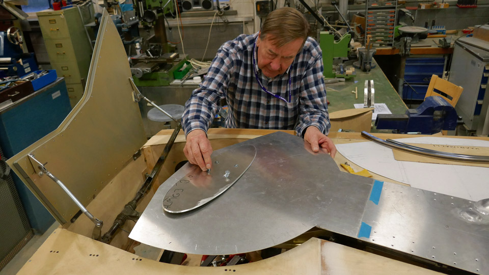
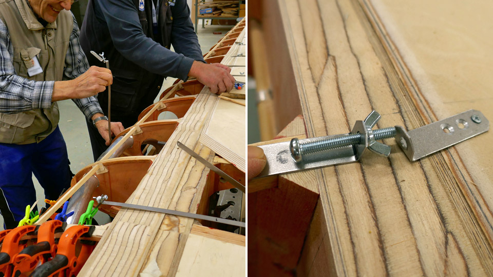
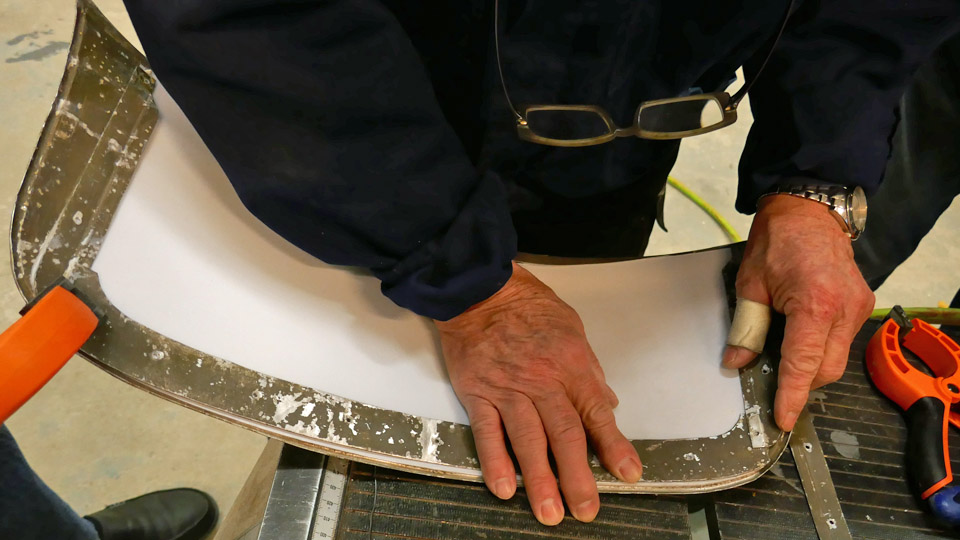
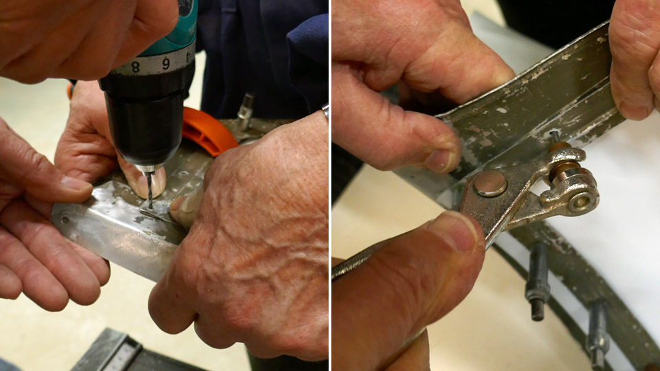
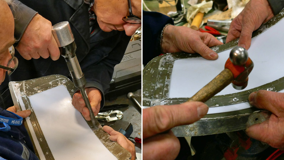
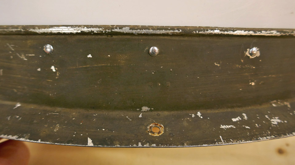
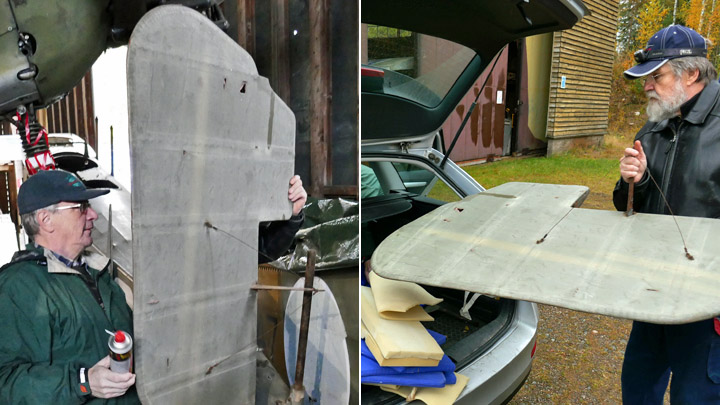
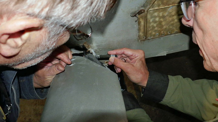
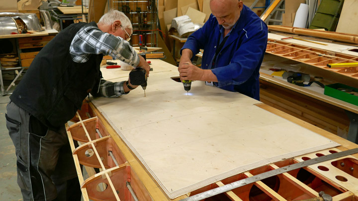
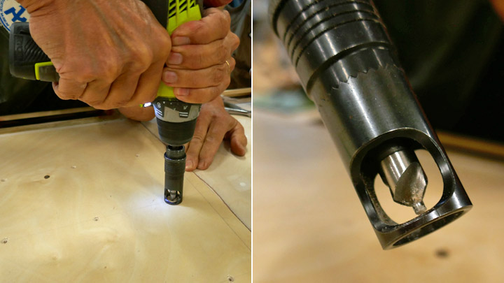
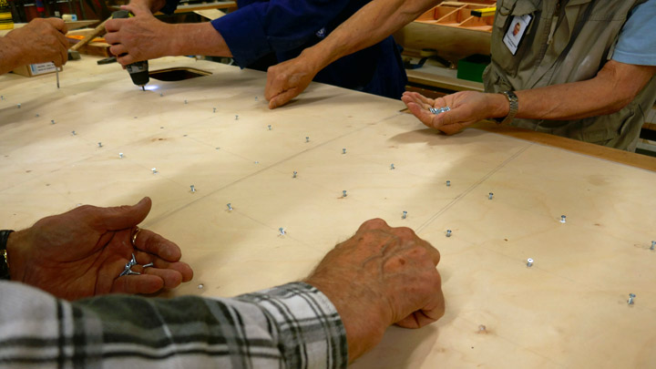
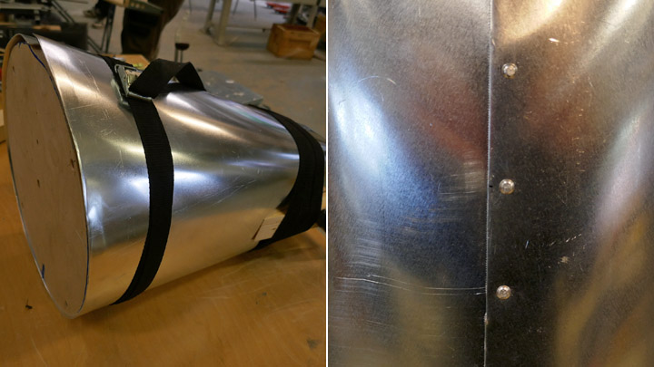
The oval stiffening plate on the outside of the outer door of the wheel well was fastened on the wheel hub with four machine screws. Then the places for the rivet holes were marked on the edges of the stiffening plate. The oval plate is fastened on the door with rivets. A prick was used for marking the location of the holes. A temporary screw was fastened to both ends of the oval plate so that the stiffening plate could be pressed tightly on the slightly convex door. The screws keep the stiffening plate in its place on the door while the rivet holes are being drilled.
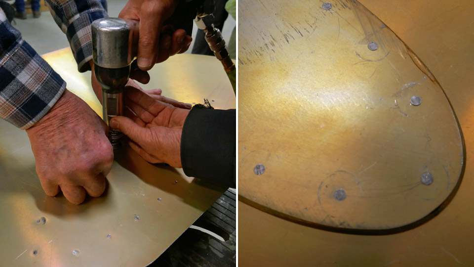
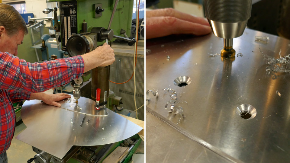
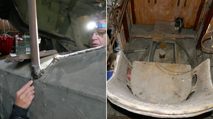
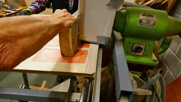
The holes were drilled using a vertical drill and beveled with a beveling drill bit. Then the stiffening plate was riveted on the door, from the inside of the door, using a riveting gun.
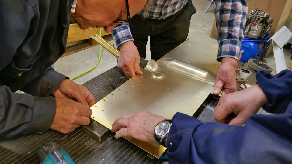
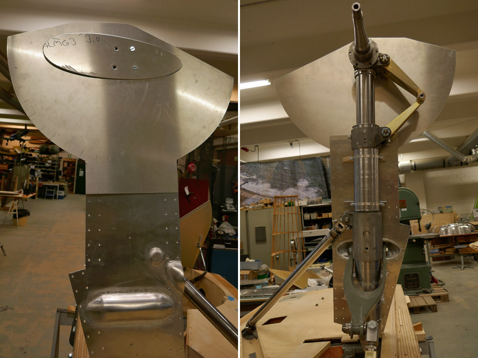
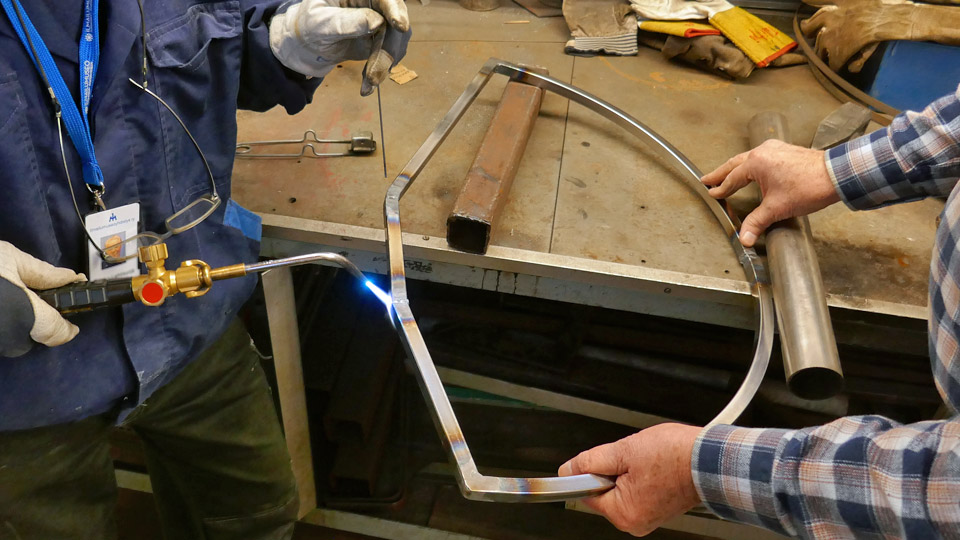
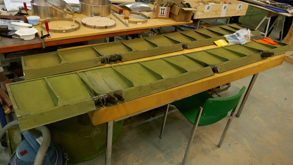
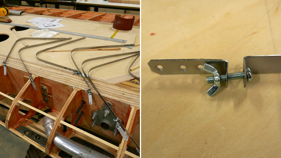
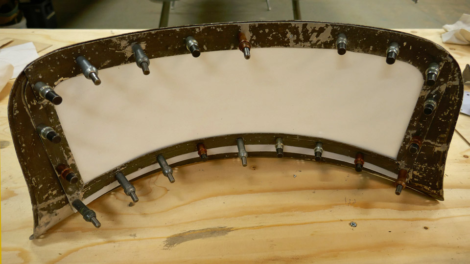
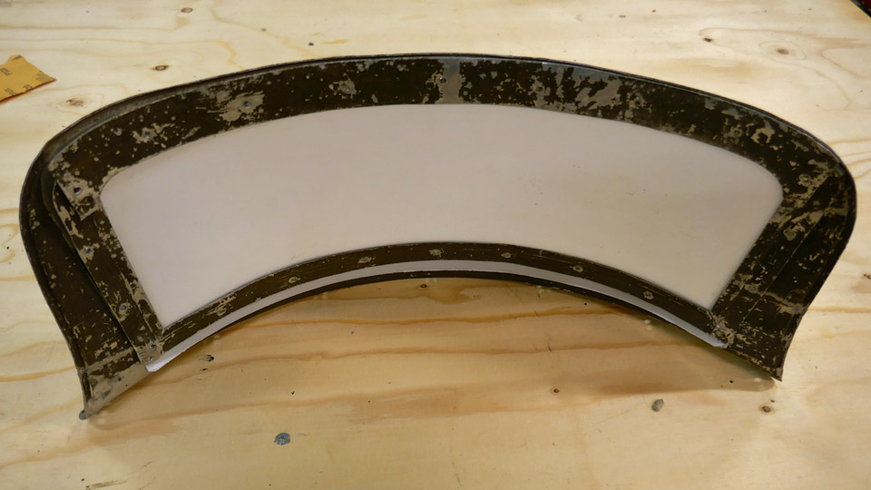
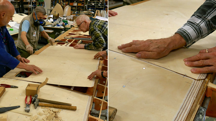
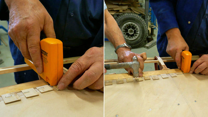
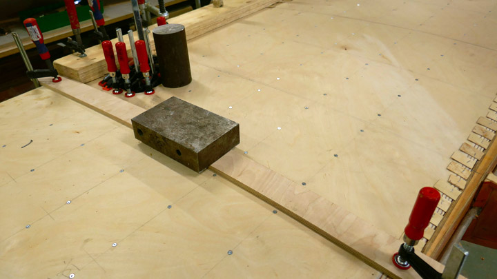
Then the box shaped stiffeners were preliminarily placed on the inner side of the outer wheel well door. There are stiffeners on both sides of the door and one at the bottom edge. The stiffeners are riveted by their outer edge on the supporting frame around the inner edge of the door, made of square steel tube, and by their hems on the door. The supporting frame of steel tube was not chromated but painted with grey Isotrol paint to prevent it from rust.
The riveting of the box-shaped stiffeners was not started before the Tuesday Club activities were terminated due to the Corona virus pandemic. The stiffeners were riveted on the oleo door but the stiffeners on the outer door of the wheel well are still under work. The landing gear of the test wing will have to wait until the work continues after the virus epidemic is over. Photos: Lassi Karivalo Translation: Erja Reinikainen |
|
Avainsanat: aviation history, restoring, old aircraft, VL Myrsky II, MY-14 |
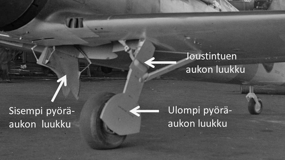
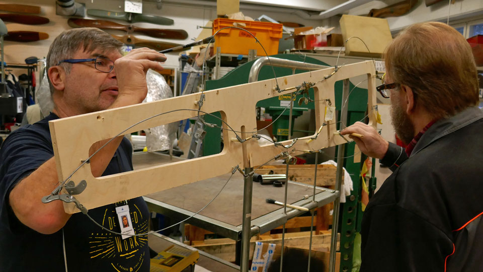
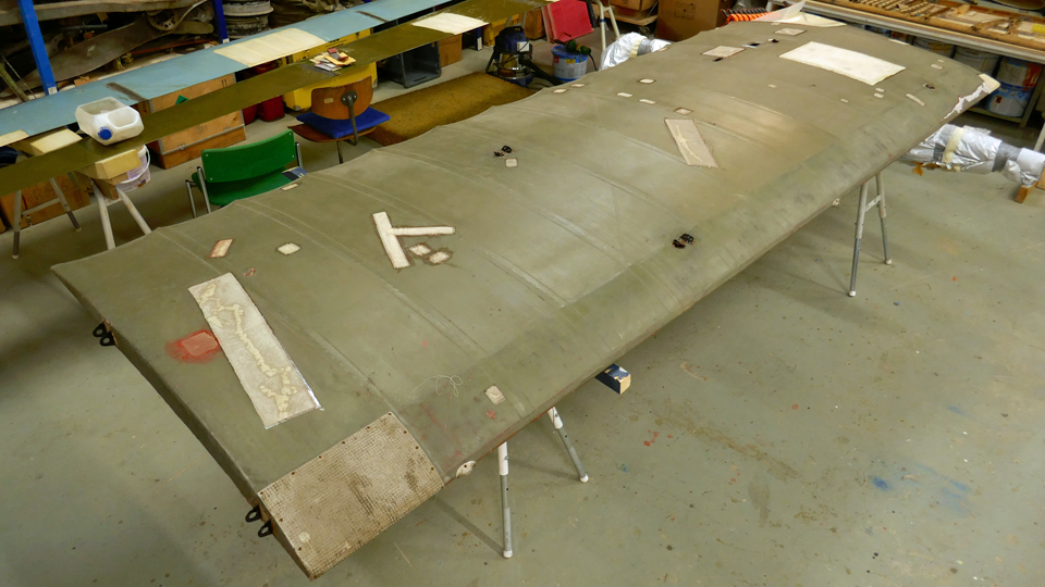
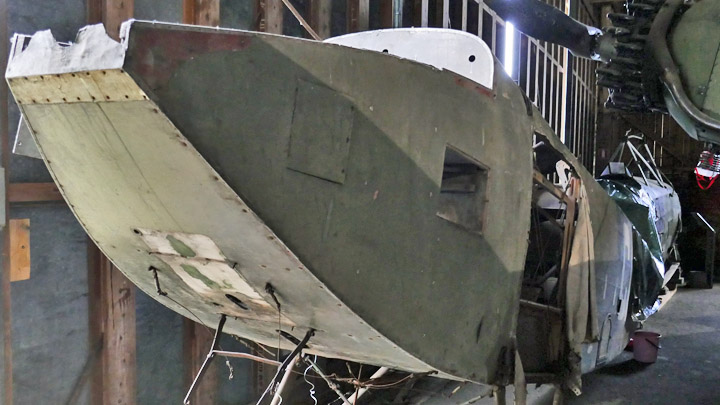
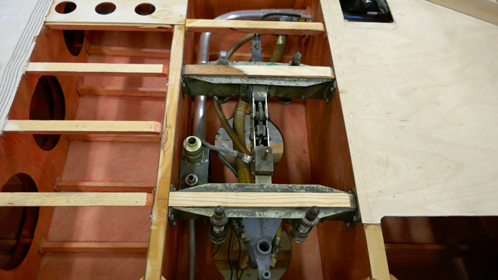
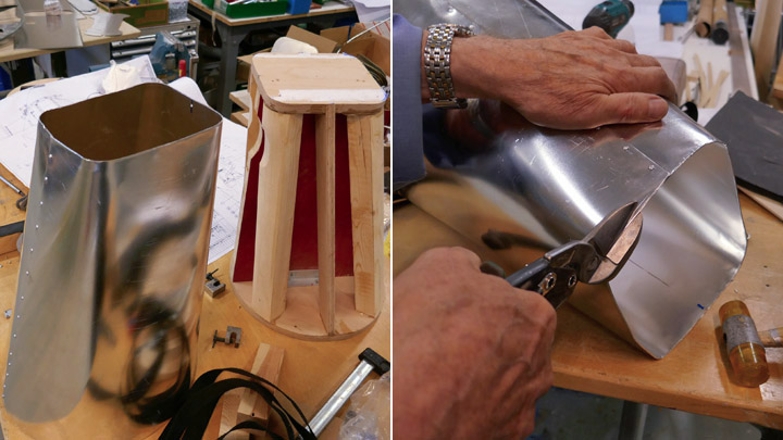
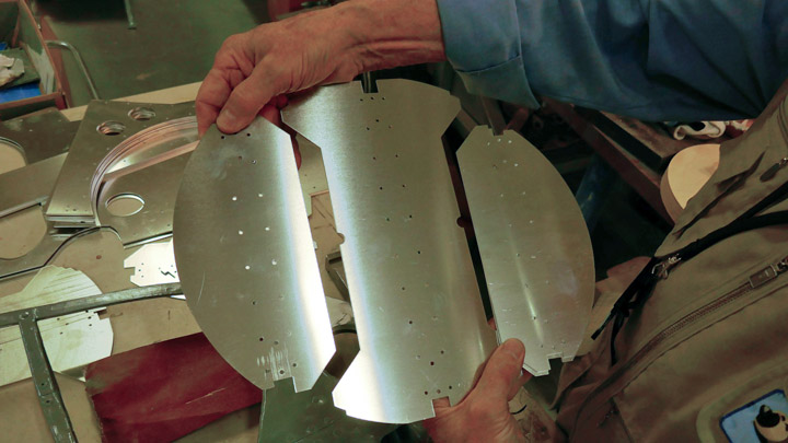
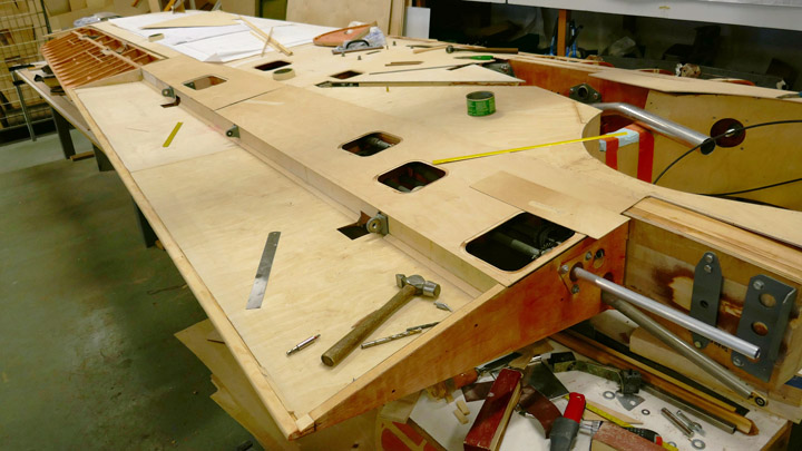
Wheel well and oleo doors for Myrsky are madeTiistai 7.4.2020 - Member of Tuesday Club Retractable landing gear was common already in WW2 fighters and VL Myrsky is not an exception. At the root of Myrsky’s wing there is an enclosure for pulling in the landing gear. The enclosure consists of a wheel well for the wheel and a compartment for the oleo (the shock strut of the landing gear). One half of the wheel well opening is covered by the inner door, made of aluminum plates, also called “daisy cutters”. The door is fastened on the inner edge of the wheel well with hinges. This door is opened automatically by a spring lever when the landing gear is taken out and it is closed by the wheel when the landing gear is taken in.
The other half of the wheel well is covered by the outer door, which is made of aluminum plate and fastened on the wheel hub, it is a pair for the “daisy cutter”. The oleo enclosure door is made of aluminum plate as well and it is fastened angel on the oleo. These two doors on the landing gear are overlapping at a distance of about 20 cm and they slide against each other when the landing gear oleo is flexing. The wheel is fastened by its axle on the “piston rod” which moves inside the oleo. The landing gear can’t have one solid door fastened on the wheel and oleo because this would disturb the vertical flexing movement of the wheel. The Tuesday Club team made first the inner doors for MY-14 wheel wells on the test wing and the actual wings. Then the construction of the outer doors and the oleo doors was started. The team decided to make the doors for the test wing first.
A laser cutter was used when cutting the semi-finished shape of the oleo door from 1.5 mm aluminum plate according to Myrsky’s original drawing. At the same time a hole was cut into the plate where the retraction mechanism fork connects to the oleo. Holes were drilled along the edges of the door where stiffening battens will be riveted.
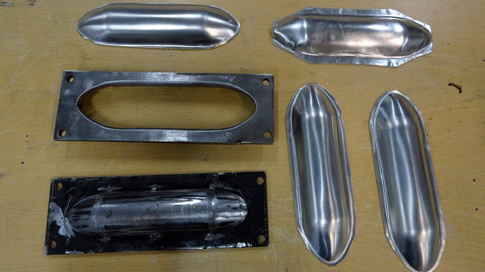
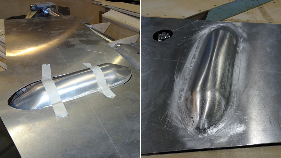
A small canopy is needed to cover the hole where the retraction mechanism fork connects to the oleo. A metal mould was made first and the canopy was pressed against it from aluminum plate. The canopies were made for the test wing and for the actual wings. The canopy was welded onto the edges of the hole on the door. After this the pre-cut door was fitted into place into the oleo opening and fastened on the temporary plywood brackets on the oleo. Eventually the door will be riveted on the brackets which are welded onto the oleo.
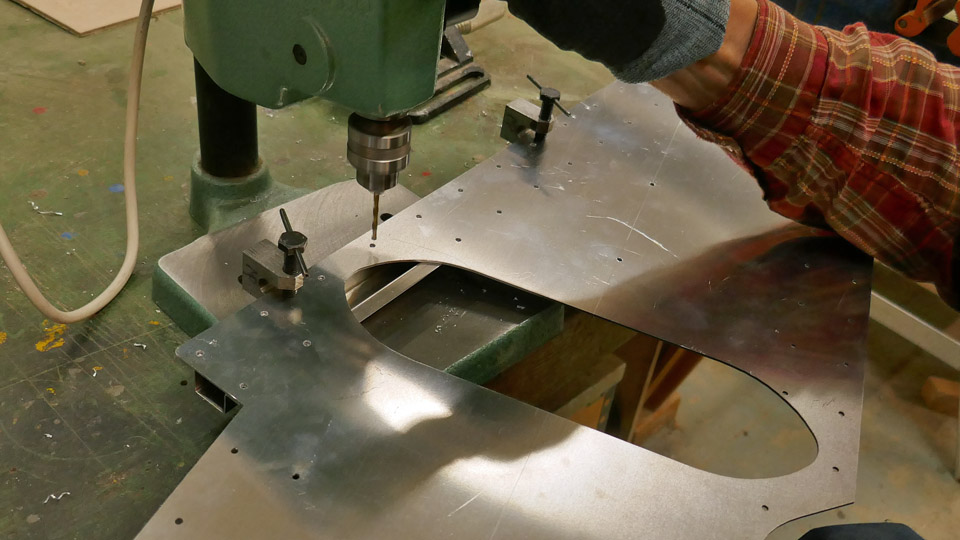
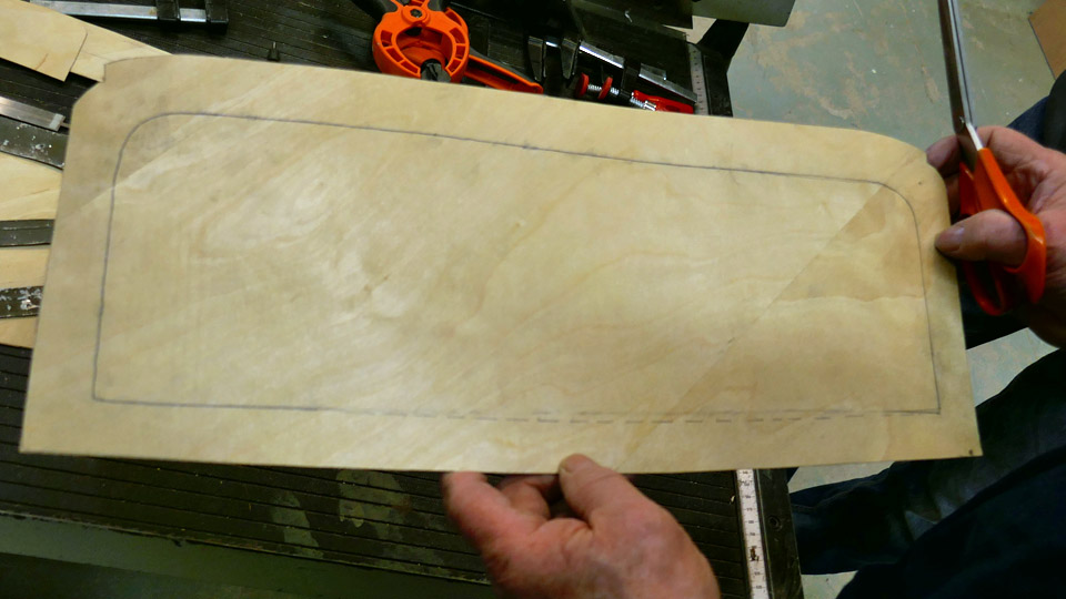
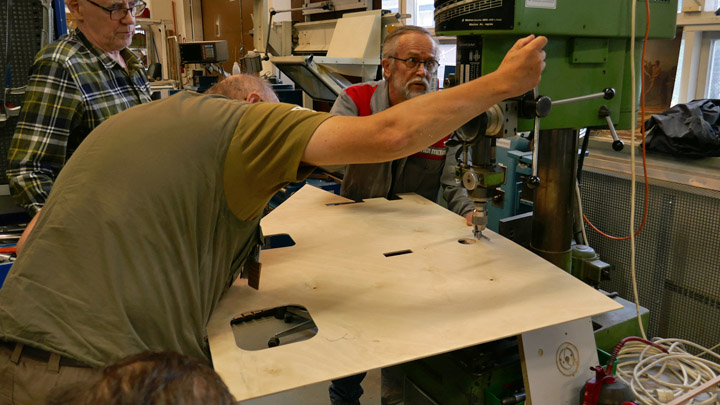
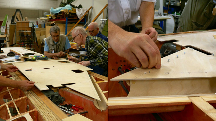
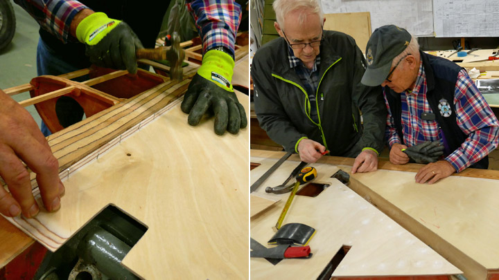
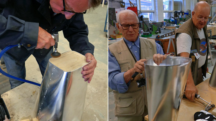
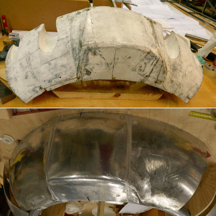
The semi-finished shape of the outer wheel well door was also cut from 1.5 mm aluminum plate with a laser cutter. The door is fastened on the wheel hub with four 6 mm flat head machine screws. The holes on the door for the screws have to be exactly in the right position to meet the threaded holes on the wheel hub. The positioning was done by placing a positioning plate with sharp-pointed markers on the wheel hub. A marker was also placed in the middle of the hub. Then the door was positioned carefully into the wheel well and the plate surface was tapped against the marker points. Now there were clear marks on the lower side of the plate for drilling the holes for the screws. The marker marks were strengthened with a spike before making the holes with a vertical drilling machine.
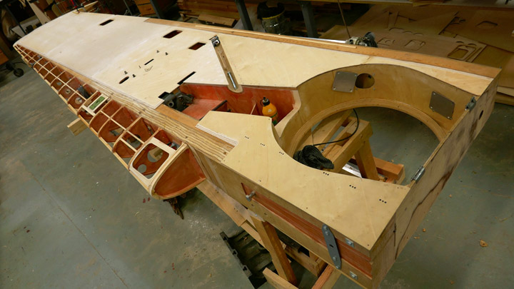
The door fastened on the wheel hub has an oval-shaped stiffening plate on the outside. It was cut from aluminum plate. The stiffening plate is fastened on the door with the four machine screws which fasten the door on the wheel hub. Holes were made on the oval stiffening plate and the edges were beveled. The stiffening plate will also be riveted on the door by its edges. The outer wheel well door was fastened on the wheel hub with the oval stiffening plate attached. Now the test wing landing gear had both doors in place for the first time. They are well visible when the landing gear of the test wing is taken out.
There will be stiffeners and supporting battens on the inner surface of the outer door in the wheel well. A supporting frame made of rectangular steel tube will be fastened on the edge of the door. The lower part of the door will have box construction strengtheners made of aluminum plate.
Pre-cut strengtheners for the inner surface of the wheel well door were cut from aluminum plate with the laser. They were modified to be fitted and fastened into place. Also the stiffeners for the oleo door are now ready. The stiffeners will not be riveted on the doors before the half ready doors and the stiffeners have been chromated. The chromate treatment will prevent the aluminum plate from oxidizing and it will be done by an outside supplier. Photos: Lassi Karivalo Translation: Erja Reinikainen |
|
Avainsanat: aviation history, restoring, old aircraft, VL Myrsky II, MY-14 |
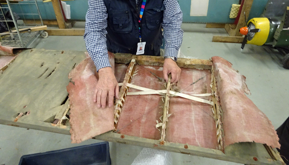
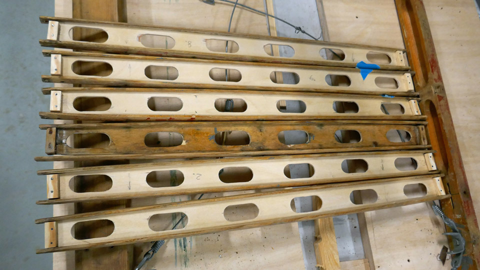
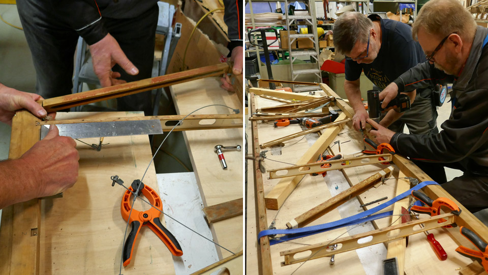
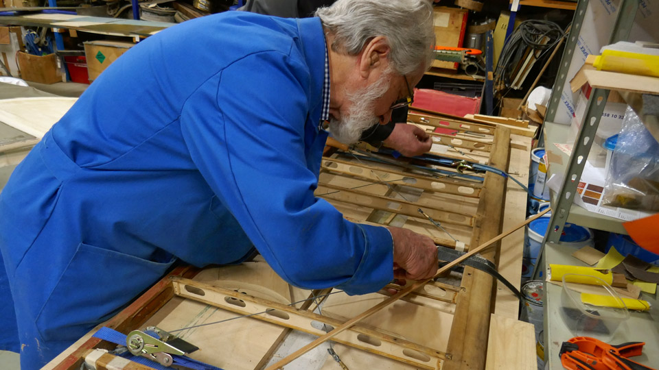
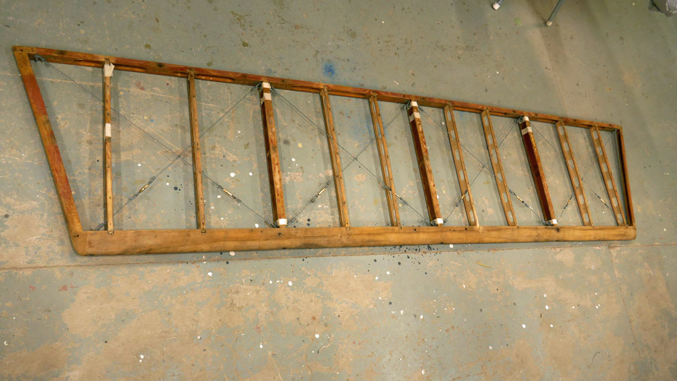
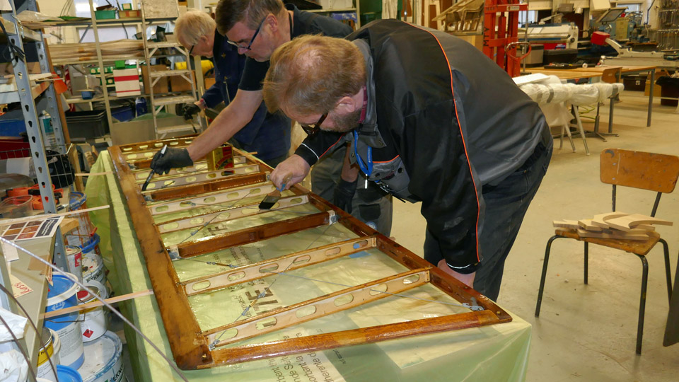
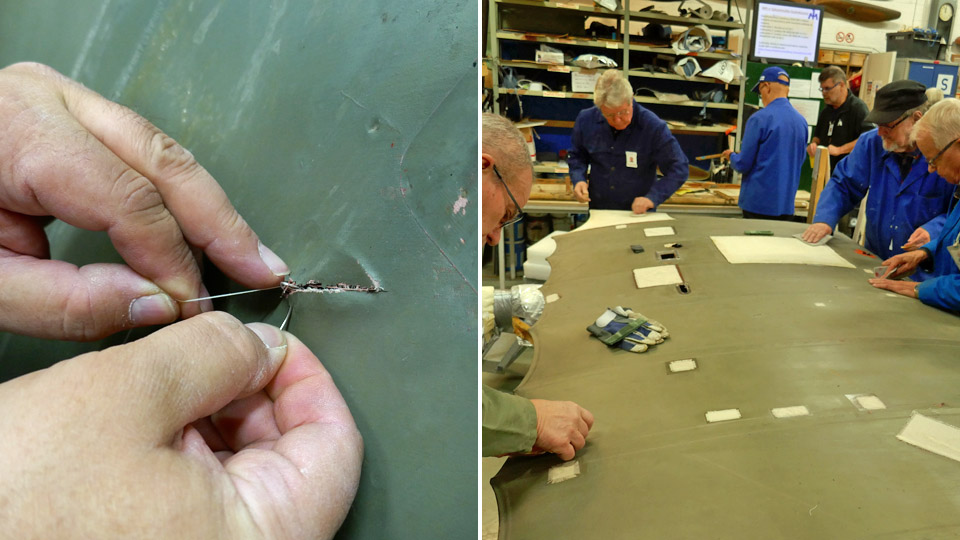
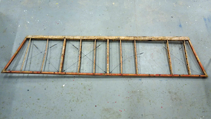
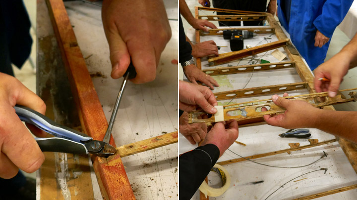
Ribbons of Caudron's horizontal stabilizer frameMaanantai 30.3.2020 - Member of Tuesday Club The horizontal stabilizer frame of Caudron C.59 (CA-50) had bent during the years and it had to be dismantled and straightened. The restoration work was finished in early February – as described in an earlier blog – and the frame was now ready for covering. Before the actual covering with fabric, ribbons or strips of fabric were fastened on the ribs of the stabilizer and its leading edge. The fabric covering will be fastened by sewing on these ribbons.
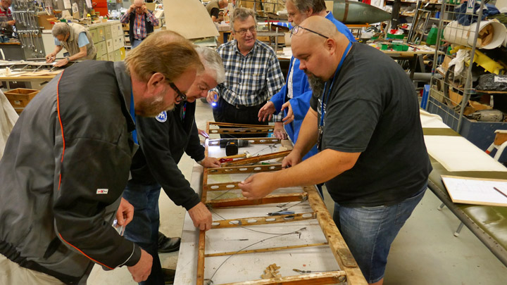
Before starting to install the ribbons on the horizontal stabilizer, the Tuesday Club team studied carefully the pictures taken of the dismantling phase, the dismantling report and the pieces of fabric covering, which still had some original ribbons attached. Based on these sources the team could see clearly how the stabilizer frame of the CA-50 had been covered and how the ribbons under the covering had been fastened.
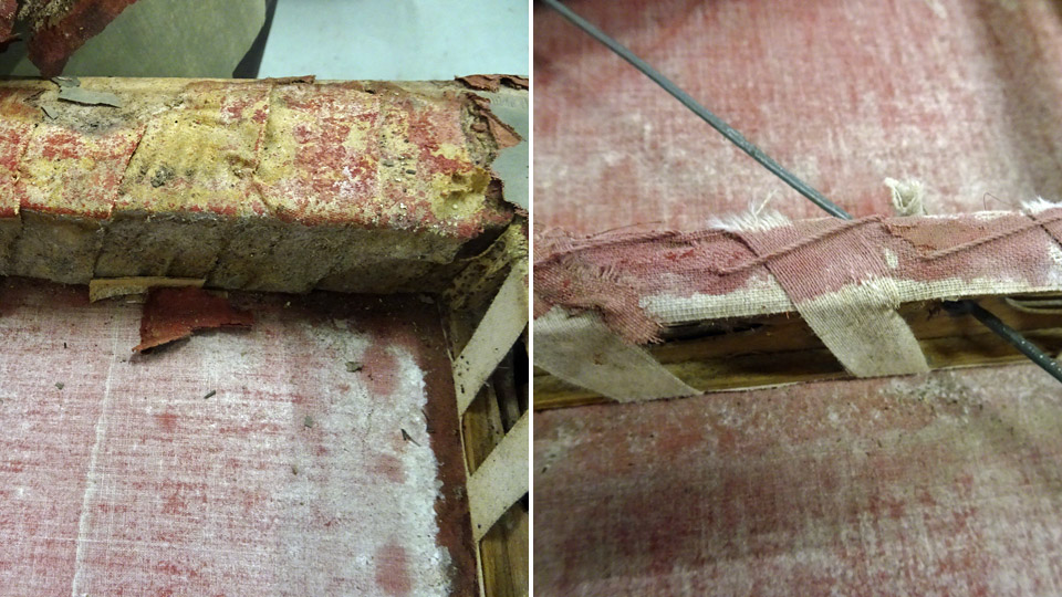
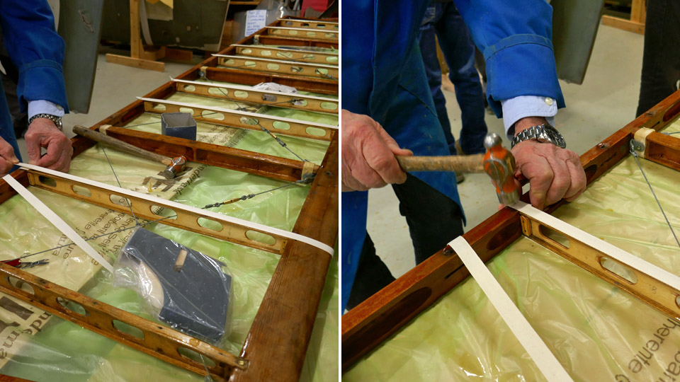
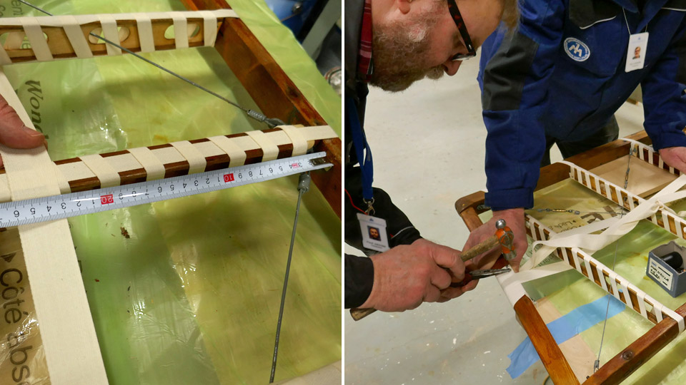
The leading edge of the horizontal stabilizer had been tightly covered with a 50 mm wide strip of fabric. The trailing edge and the end battens on the stabilizer didn’t have any ribbons around them. The ribs had 15 mm wide ribbons around them: first a ribbon had been tied along the upper and lower edge of each rib and then it had been tied on the rib, using another 15 mm wide ribbon which was spun around the rib. The leading end of the ribbon used for spinning had been fastened on the leading edge with tacks and the far end fastened on the rib root.
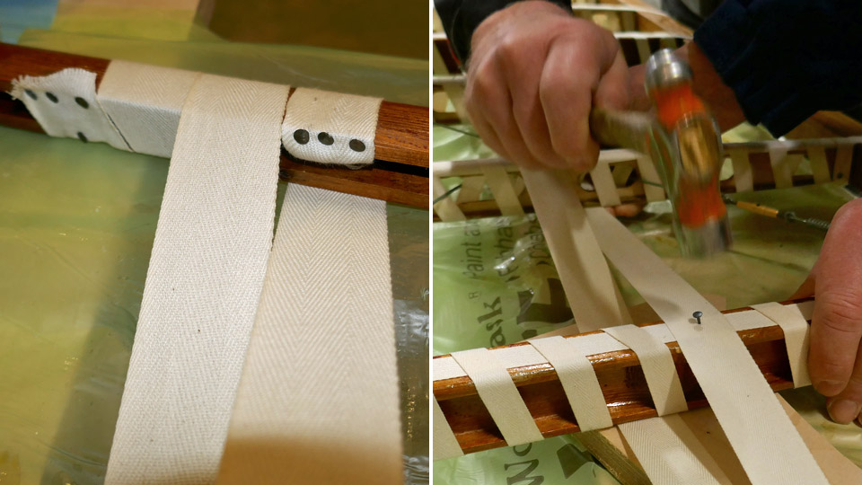
The stabilizer ribs had also been connected to each other at the middle, using a 30 mm wide ribbon with its ends fastened on the end battens of the stabilizer. The ribbon connecting the ribs had been woven through the ribs so that it ran under every other rib and over every other. The ribbon ran weaving over and under the ribs between the end battens.
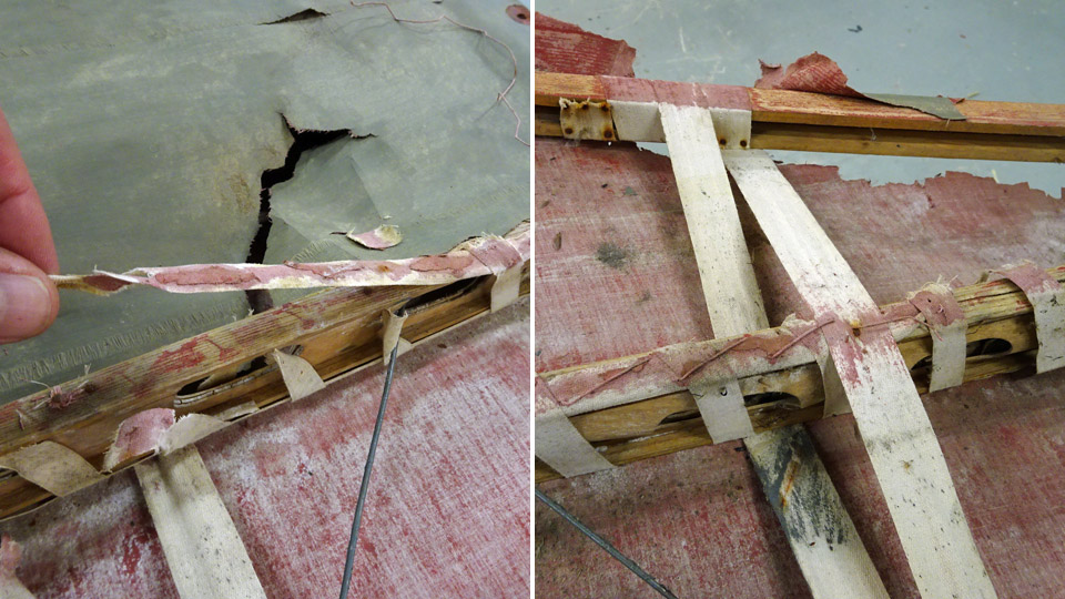
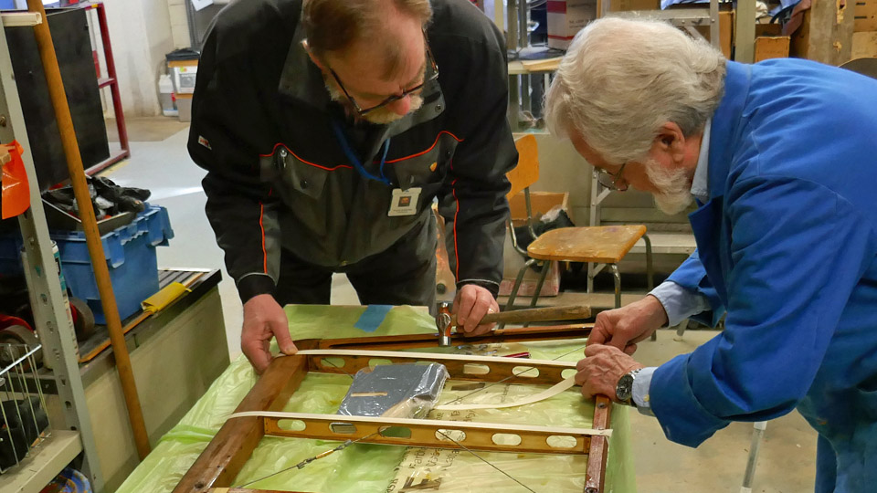
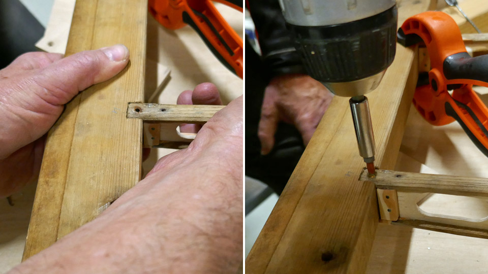
The Tuesday Club team started the ribbon work on the restored horizontal stabilizer frame on the plywood ribs. The leading end of the ribbon was fastened on the leading edge with two tack nails, on the rib position. Then the ribbon was pulled along the upper edge of the rib as far as the trailing edge, around it and along the lower edge of the rib back to the leading edge. There the end of the ribbon was fastened on the starting point with another tack. The same procedure with the ribbon was followed when working all eight plywood ribs.
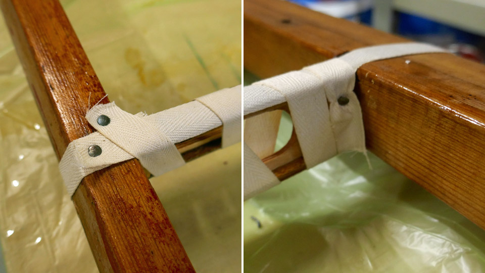
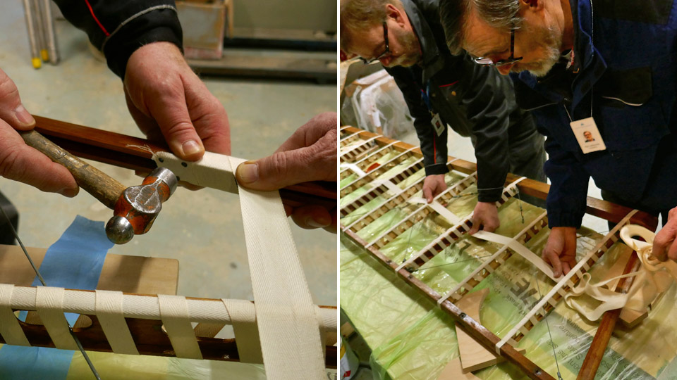
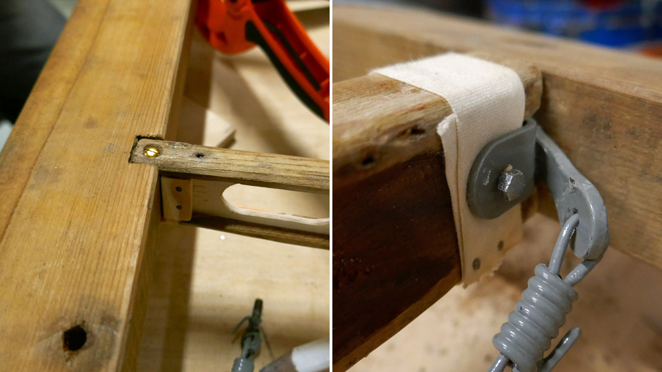
The following phase was to fasten the ribbons on the ribs into place by spinning another ribbon around each rib. Based on the pictures taken of the cover dismantling, the leading edge of the spinning ribbon was nailed with two tacks on the lower side of the trailing edge batten, where it met the ribbon running along the rib. Then the ribbon was tied diagonally around the rib, with 3 cm wide spaces between each round. At the other end of the rib the ribbon was fastened on the strengthening piece of plywood at the root of the rib. When the eight normal ribs on the stabilizer had been spun, the same principle was used when spinning the three solid wood ribs, which support the stabilizer structure.
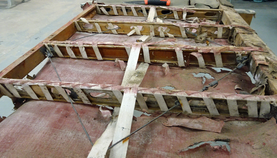
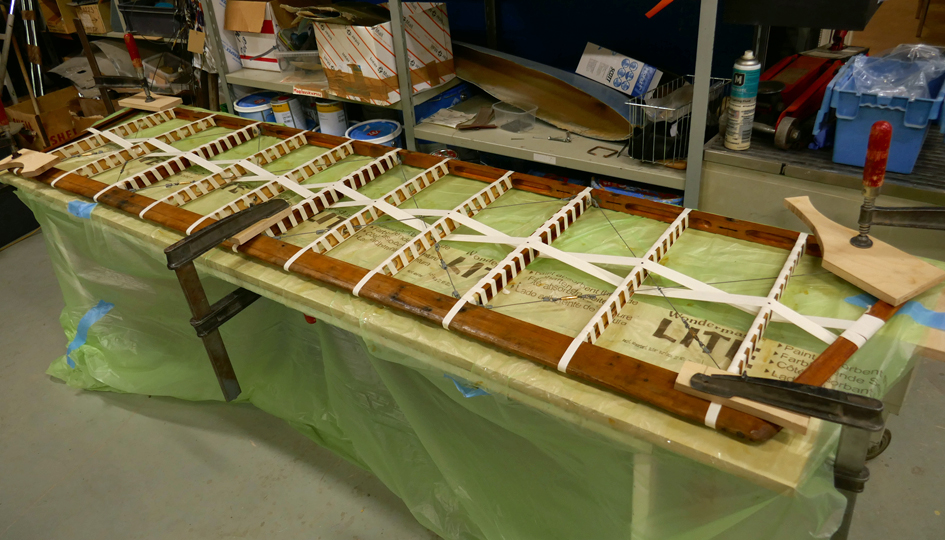
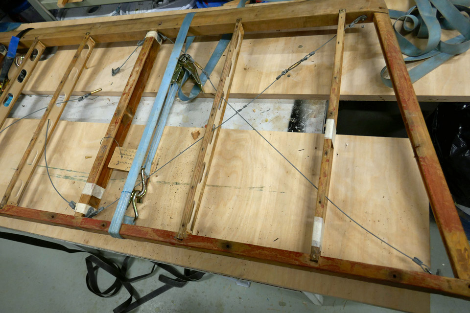
When the ribs had been spun with ribbon, the 30 mm wide strip of fabric connecting the ribs was fastened. The leading end of the wide ribbon was fastened with four tack nails onto the inner side of the port end batten, following the original installation. Then the ribbon was spun a couple of times around the end batten before weaving it over and under every other rib until the starboard end batten. Also the location of the ribbon was checked so that it ran halfway along the ribs. The ribbon was locked into place with a tack on the starboard end batten. Then the ribbon was woven in a similar manner back to the port end batten and fastened on it with three tack nails. Finally the ribbon was nailed onto each rib’s upper and lower batten.
The ribbons on the horizontal stablilizer’s leading edge of the Caudron C.59 were not installed before the Tuesday Club’s activities were interrupted due to the corona virus pandemic. Photos: Lassi Karivalo Translation: Erja Reinikainen |
|
Avainsanat: aviation history, restoring, old aircraft, Caudron C.59, CA-50 |
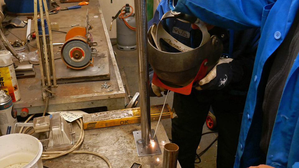
Other than restoration activities in Tuesday ClubMaanantai 23.3.2020 - Member of Tuesday Club The Tuesday Club of the Finnish Aviation Museum Society is mainly connected to restoring and repairing old aircraft and placing them on display in the aviation museums. Mainly this is naturally true, but the Tuesday Club is involved in various other activities which support the functions of the Aviation Museum or the Aviation Museum Society. This blog introduces some examples of these activities. Legs for large display monitorsThe Aviation Museum Society purchased six large display monitors, second-hand but functioning, to be used in different in public events connected to aviation. The bargain didn’t include legs which are needed when the display is standing on a table. Therefore the Tuesday Club team was given the task to make two legs for each display.
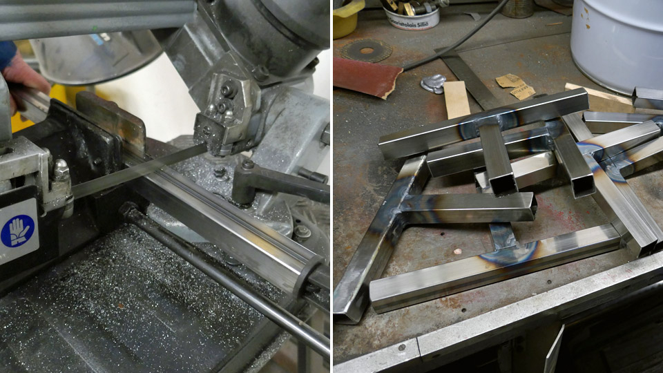
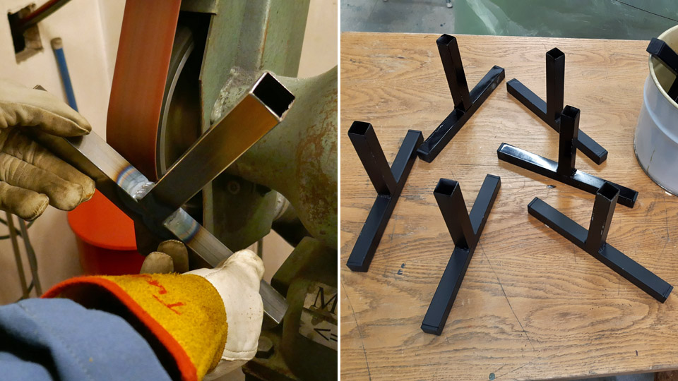
The team decided to make T-shaped legs from metal tube. The legs could be installed into the holes in the lower edge of the display and unfastened after use. The team acquired rectangular metal tube with suitable dimensions and cut it into pieces which will be welded together to form the T-shaped leg. For each display two tube pieces were needed for the horizontal legs and two pieces for the vertical supports. A total of two dozen tube pieces were cut for the six displays.
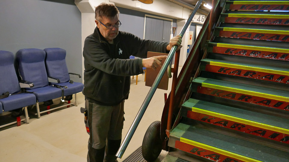
The 12 T-shaped legs were welded in the welding space outside the Finnish Aviation Museum. The welded seams and the ends of the tubes were ground smooth and then painted black. Finally the square tube ends of the legs were plugged using black plastic plugs. Now all six displays had their legs ready and they can be used in the different aviation events. Extending the guard railing of the stairsVisitor safety is important for the Finnish Aviation Museum. When inspecting the safety issues, a shortcoming was noticed on the stairs leading to the balcony of the I Hall. The guard railing of the stairs was shorter than the staircase. This may be dangerous for the visitor when the railing suddenly ends and there are still more stairs to walk. The museum decided to build extensions to the railings.
For the new railings the Tuesday Club team acquired stainless steel tube, which is strong enough and has a glossy polished surface which doesn’t need additional polishing. The tube will be connected to the existing railing tube using a lapped joint.
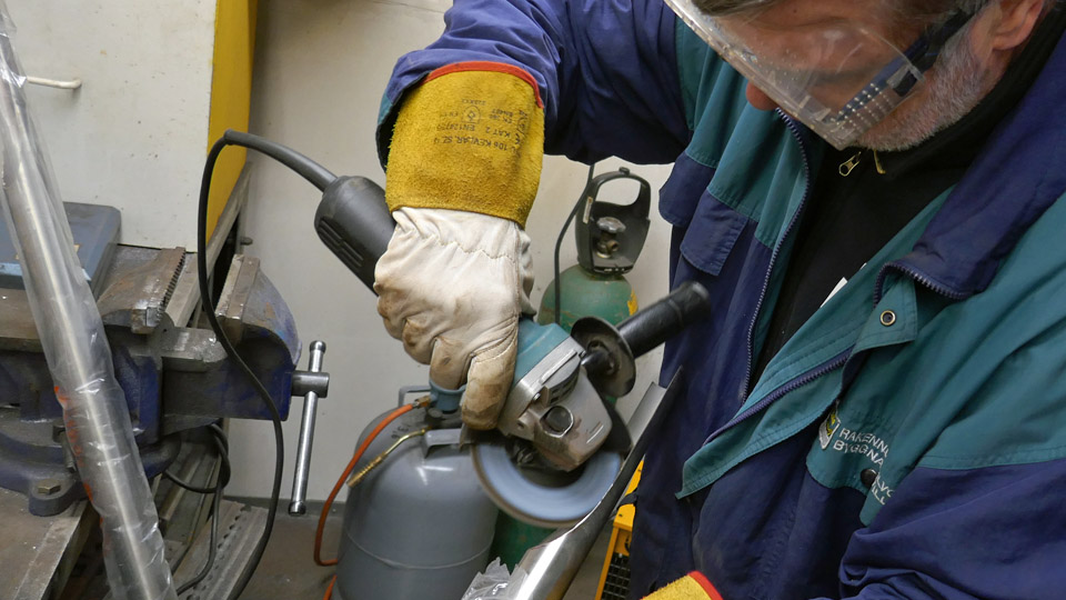
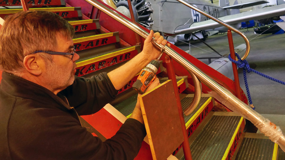
The lapped joint is made by cutting away the lower part of the tube at a length of about 30 cm. The open curved end of the railing tube can be pressed tightly on the original handrail and fastened with brackets on the vertical balustrade. The joint of the stainless steel tube on the original handrail will be made first on one railing to test how it works. When the joint has reached the desired form and appearance, the other three railing extensions can be made according to the model and using serial production process. The first joint is already in the testing phase.
The extended handrails will naturally need their own vertical balustrades. The balustrades will be made from ordinary steel tube which was cut into four pieces. Fastening plates were welded onto the lower end of each balustrade tube. Fastening brackets for the handrail will be welded to the upper ends of the tubes.
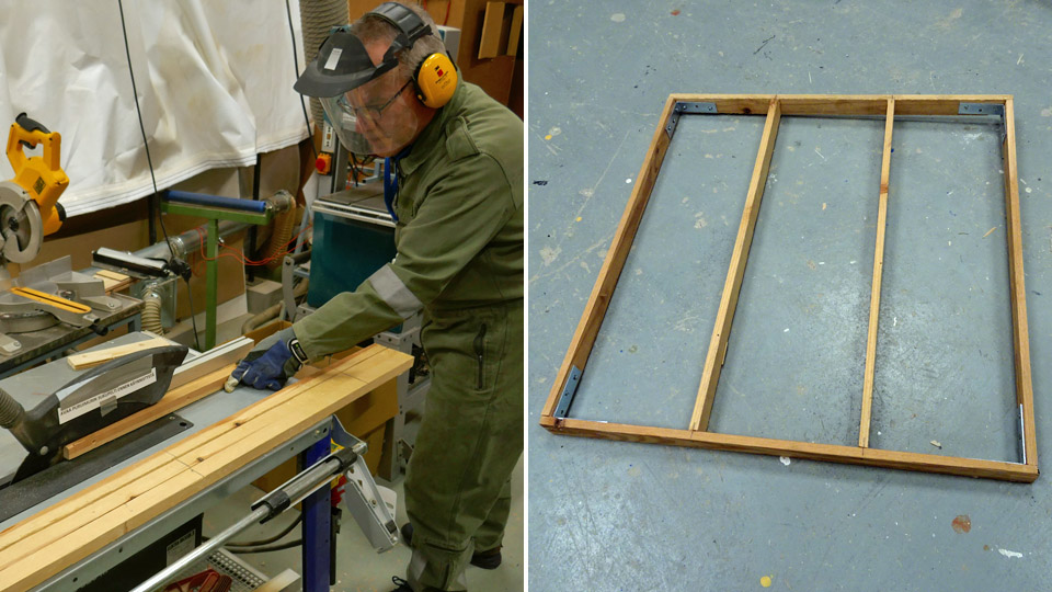
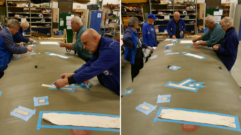
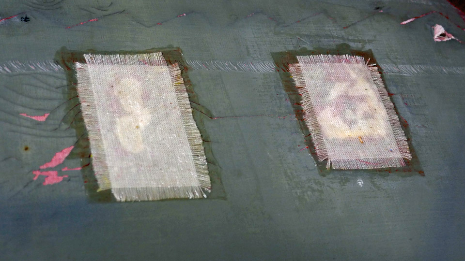
Now the guard railing extension project is at the phase where the joint of the extended handrail and the existing handrail is finalized and the balustrade tubes are made. However, the corona virus pandemic interrupted the Tuesday Club activities at the Aviation Museum and the work will be continued when the pandemic is over. Paint testsThe Tuesday Club is working on the restoration of the VL Myrsky II (MY-14) fighter and the Caudron C.59 advanced trainer plane and the rotor blades of the SM-1 helicopter (HK-1) are being repaired. Each project is now reaching the painting phase. The exact paint type and colour originally used on the Caudron and the helicopter rotor blades are not known. Also the fabric-covered parts of the Myrsky will require paint tests. The test is not only about paints but also different kinds of cotton and linen fabrics will be tested how they fit the needs. The Tuesday Club team decided to make a dozen wooden frames, covered with fabric, for testing the paints and different kinds of fabrics and for choosing their combination.
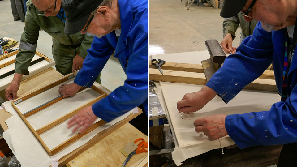
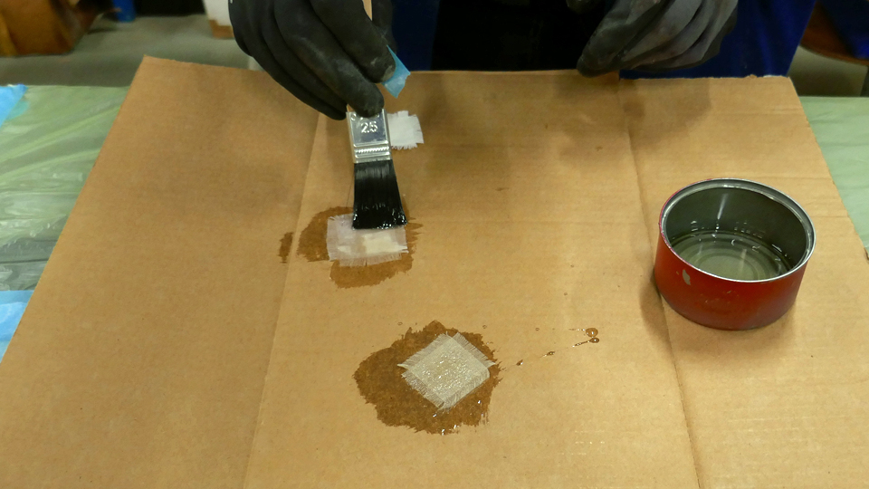
Suitable batten material was found in the wood storage of the restoration space and it was cut to measure. The battens were connected to form frames of 50x50 cm. The frames were covered with four different kinds of cotton fabric and a linen fabric. On some frames the fabric was properly sewn, as it would be when covering an airplane with fabric. On other frames the fabric was fastened using a stapler.
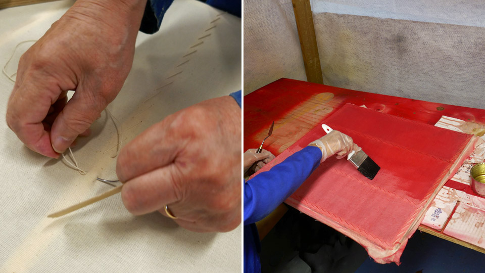
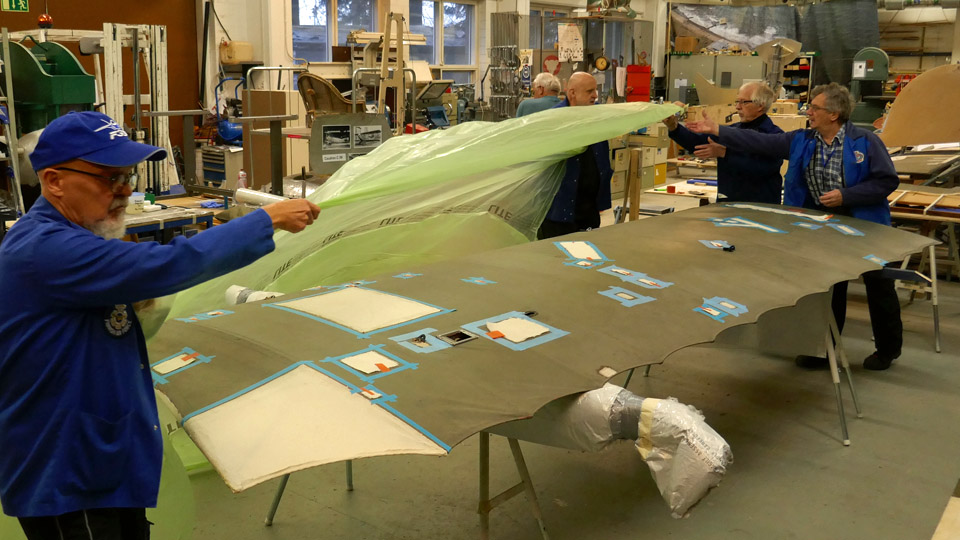
When the frames were ready, the fabric was tightened using nitrocellulose varnish. The fabric has to be tightened before the paint tests. The fabric has to be covered with the shrinking dope several times before it is tight enough. The shrinking procedure is started with thinned varnish (50% varnish, 50% thinner) and finished with plain varnish.
The shrinking process was left unfinished when the corona virus pandemic interrupted the Tuesday Club activities. Hopefully the pandemic is soon over and the team can return to their normal routines. Photos: Lassi Karivalo, translation: Erja Reinikainen. |
|
Avainsanat: aviation history, restoring, old aircraft, Tuesday Club |
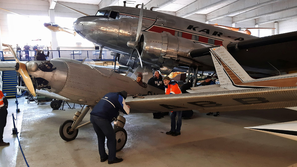
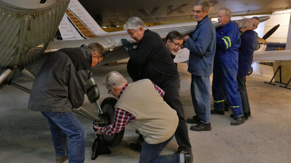
Metal trestles for Junkers 50A Junior and repairing of Junnu's modelKeskiviikko 18.3.2020 - Member of Tuesday Club The Junkers 50A Junior was on display at the Helsinki-Vantaa airport for many years, but it was returned to the Finnish Aviation Museum about a year ago because of the refurbishment works in the airport terminal. This aircraft is the famous OH-ABB, registered on 6.3.1931 by Väinö Bremer, who flew several long distance flights on this plane. In 1932 one of his flights reached from Finland all the way to Cape Town in South Africa and back.
So far Bremer’s Junkers has been in storage at the Finnish Aviation Museum and hidden from the public. Now the “Junnu” has been placed on display in the II Hall of the museum. At the moment the museum is closed because of the corona virus epidemic, but the plane can be admired later. The plane was moved and assembled by the museum’s hot air balloon volunteers together with the museum staff.
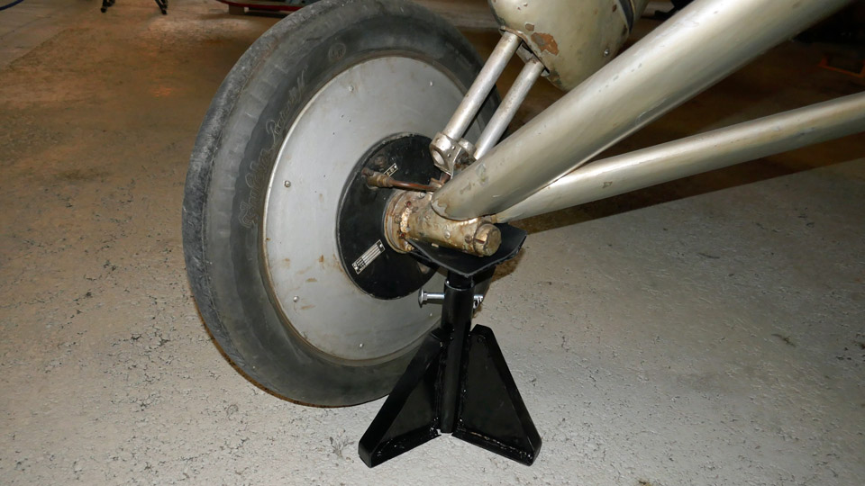
The Junkers is standing in the II Hall on its landing gear wheels with its full weight, so the Tuesday Club team decided to make metal supports under the landing gear wheel axles. This is a normal procedure for aircraft which are on display in aviation museums. When the metal trestles bear the weight of the plane, the tires won’t be damaged when the plane stands on display for many years.
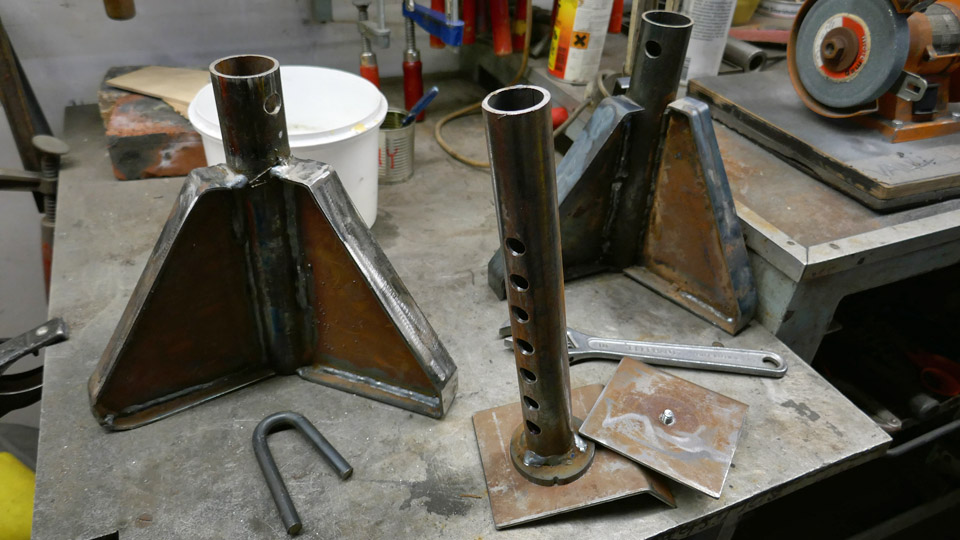
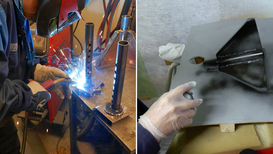
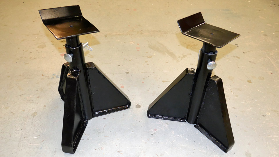
The Tuesday Club team was surprised to find half-finished metal trestles in the corner of the restoration space in the Finnish Aviation Museum. These trestles could be modified to fit the Junkers 50A Junior. The trestles were covered with rust and the surfaces needed to be cleaned. The tube-shaped adjusting spars inside the trestles had to be modified to fit the new purpose. The trestles were sprayed with black varnish paint.
The team took the modified metal trestles to the II Hall in the Finnish Aviation Museum and managed to lift the Junkers so that the trestles could be installed under the wheel supports on both sides.
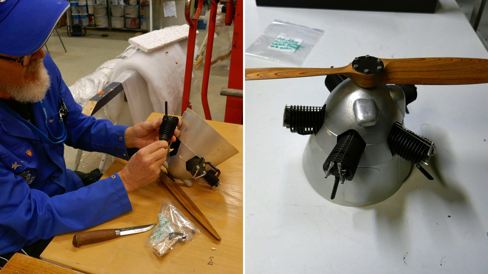
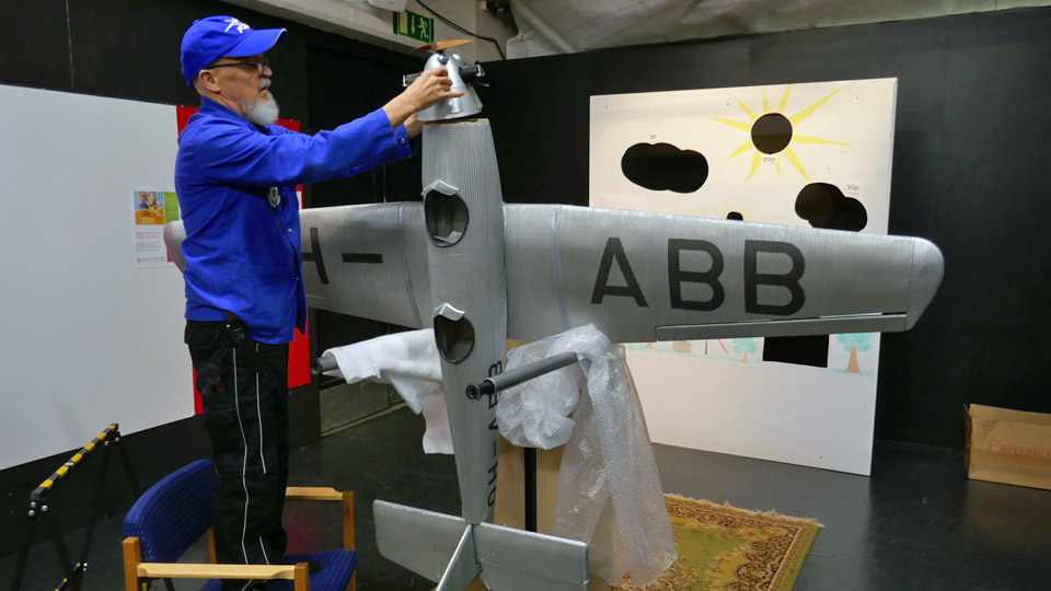
The Tuesday Club team had also another task concerning Junkers Junior. A model of the Junkers OH-ABB has been on display in the II Hall of the Finnish Aviation Museum. Its skin is made of corrugated cardboard to imitate the real corrugated metal sheet covering of the Junkers. The scale of the model was actually defined by the size of the “waves” of the corrugated cardboard.
The engine of the model had been damaged during the years and it had come loose and also the cylinders and some parts had broken. The Tuesday Club team repaired the engine and fastened it back into place.
The model was taken back into II Hall and placed beside the real Junkers 50A Junior (OH-ABB). Now the model and real aircraft are side by side, on display, with a pilot sitting in the cockpit. Photos: Lassi Karivalo Translation: Erja Reinikainen |
|
Avainsanat: aviation history, restoring, old aircraft, Tuesday Club, Junkers 50A Junior, OH-ABB |
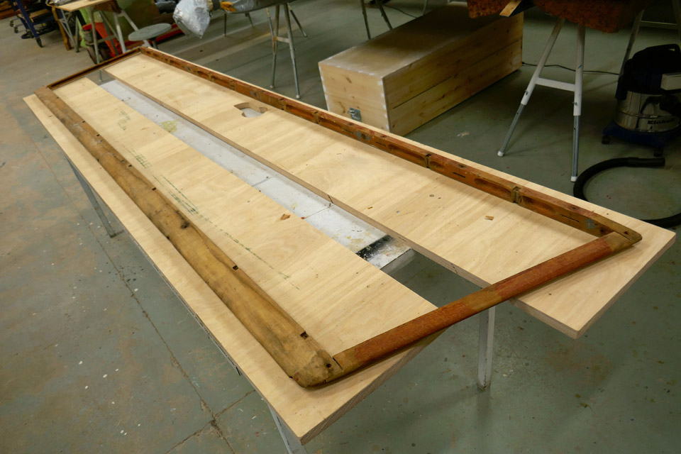
Horizontal stabilizer's frame of Caudron is repairedKeskiviikko 4.3.2020 - Member of Tuesday Club The restoration work on Caudron C.59 advanced trainer’s wooden horizontal stabilizer frame has involved a lot of work and after about six months it is finally ready. The starting point in the restoration work was that the stabilizer’s covering was rotten and broken and had to be replaced. It turned out that the whole frame of the stabilizer was bent and its ribs were rotten. The Tuesday Club team decided to dismantle the whole structure and rebuild most of the ribs, and straighten the bent battens on the leading and trailing edge.
The restoration work on the various parts of the horizontal stabilizer was completed in the beginning of this year. The ribs have been repaired, the bracing wires have been cleaned and painted and the battens on the leading and trailing edge have been straightened. On one rib the half-rotten plywood waist could be fixed with glue, but on the rest of the ribs the plywood waist had to be replaced. Before assembling the horizontal stabilizer the holes, which make the rib lighter, were made even larger to match the size on the original rib holes. This work was done using a vertical rotary tiller.
The assembly work was started by fitting the repaired plywood ribs preliminarily into their places between the leading and trailing edge battens. Some adjustment was needed on the ends of the upper and lower battens on the ribs before they fitted tightly into their places. After the fitting, the fastening of the ribs was started, beginning on the leading edge.
The ends of the upper and lower battens on each rib were pushed into the fishtail joint notches on the leading edge. Then the rib batten ends were fastened on the leading edge batten, using 3x16 mm countersunk brass screws. First a preliminary hole was made, using a thin drill piece, to prevent the batten ends from splitting. In addition to the plywood ribs, also three solid wood ribs were fastened on the leading edge batten. The fasteners for the bracing wires were fastened between the wooden ribs and the leading edge batten. The bracing wires, still attached on the fasteners, were left loose.
The Tuesday Club team didn’t use any glue when fastening the ribs and assembling the horizontal stabilizer. When dismantling the Caudron’s horizontal stabilizer, the team found out that the stabilizer has been originally built in France at the Caudron factory without any glue.
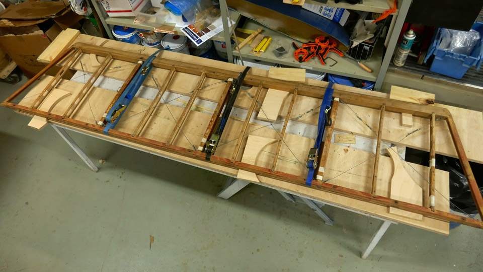
When all the ribs had been fastened on the leading edge batten at one end, the work on the trailing edge could be started. The first step was to fasten the end of each rib into its notch in the trailing edge batten. Three cargo straps were tightened around the horizontal stabilizer to keep it in shape when fastening all nine plywood ribs and three wooden ribs into place.
When all ends of the upper and lower rib battens had been fastened on the trailing edge with fishtail joints, the battens were secured using brass screws. The solid wood ribs with the bracing wires were also fastened on the trailing edge. Now the crossing bracing wires could be slipped through the lightening holes on the plywood ribs. The last step in the assembly work was to fasten the end strips of the port and starboard end of the horizontal stabilizer onto the joints at the ends of the leading edge and trailing edge battens. Now the assembly work had been completed.
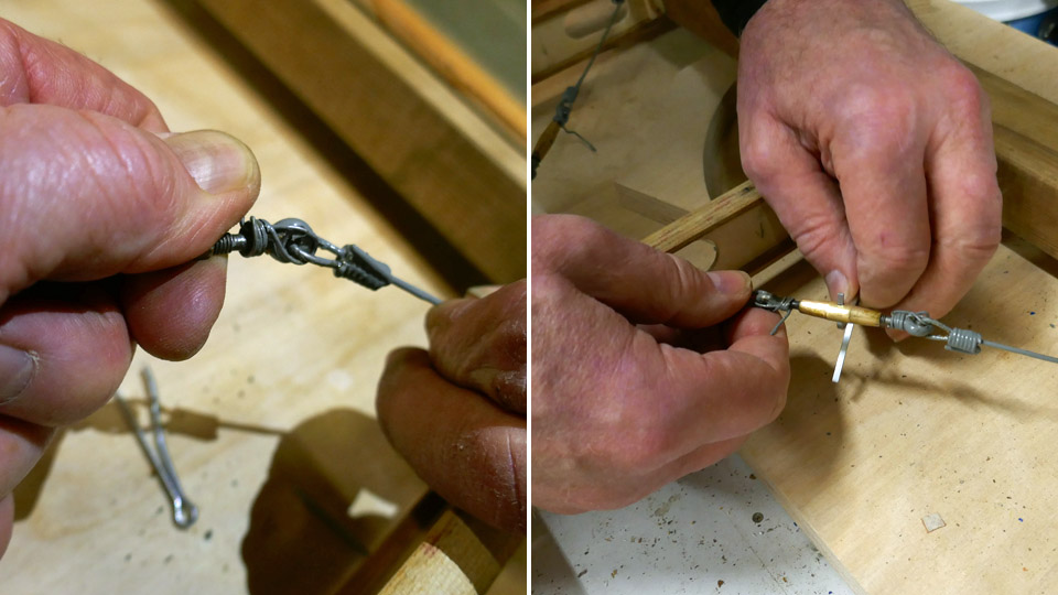
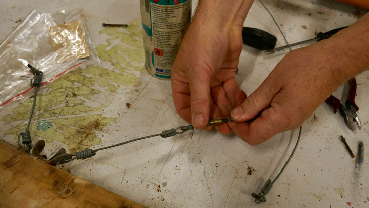
At this point the bracing wires of the horizontal stabilizer could be preliminarily tightened. The work was started by removing remaining old wire strips from the turnbuckles and cleaning the threads on the turnbuckles. Then the crossing wires were tightened using the turnbuckle. The final tightening of the bracing wires will be done before the stabilizer covering work is started.
The horizontal stabilizer had been assembled and the bracing wires preliminarily tightened, so the supporting cargo straps could be removed. When this had been done, the team noticed that the port rear corner of the stabilizer was a couple of millimetres above the table surface. When assembling the stabilizer frame, the team didn’t use any glue, so it was natural that the uncovered stabilizer will bend a little. The team managed to straighten the frame manually so that it rested evenly on the table surface.
After the assembly, the horizontal stabilizer frame was varnished using protective clear Le Tonkinois varnish. The varnish is a mixture of linseed oil varnish and China wood oil. The Tuesday Club team didn’t use varnish tinted red, as it would normally have done when varnishing a new wooden frame. Clear varnish was chosen because the team wanted to preserve some of the still remaining original red protecting varnish which had been applied on the horizontal stabilizer frame at the Caudron factory in the 1920s. Now the horizontal stabilizer is ready to be covered. Photos: Lassi Karivalo Translation: Erja Reinikainen. |
|
Avainsanat: aviation history, restoring, old aircraft, Caudron C.59, CA-50 |
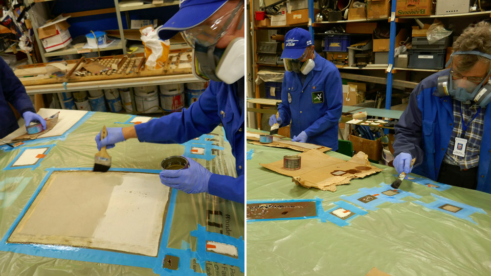
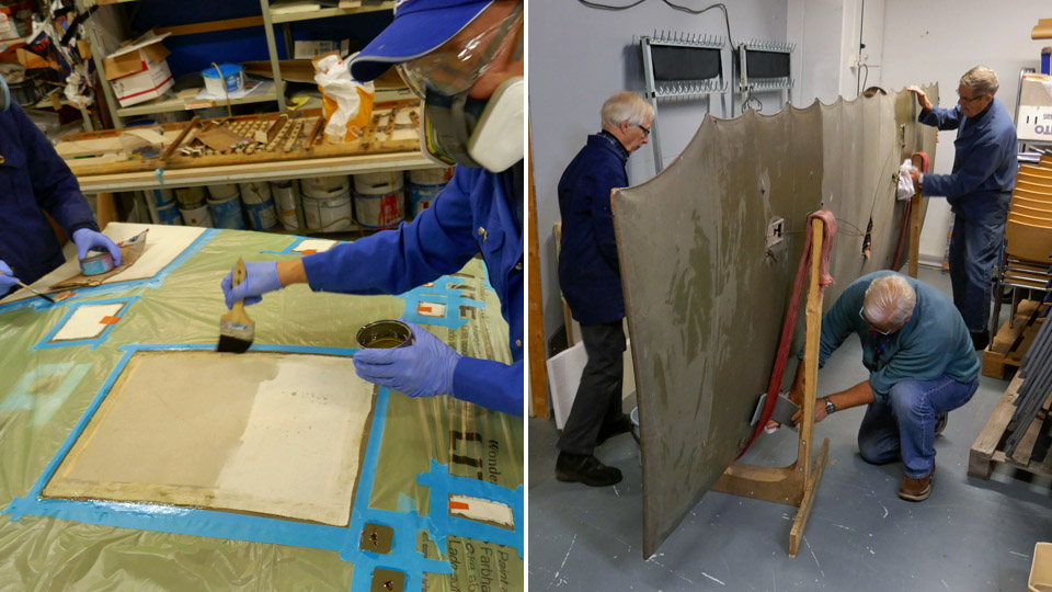
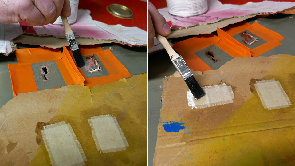
Fabric covering of Caudron's port wing is patchedKeskiviikko 19.2.2020 - Member of Tuesday Club By the end of January all holes and tears on the Caudron C.59 (CA-50) aircraft’s lower port wing have been mended. The edges of each tear were first sewn together and then a patch for each hole was cut from cotton fabric. The edges of each patch were unravelled in the manner used in the 1920s. The frayed edges help the patch to fasten tightly on the repaired area when the fabric is varnished.
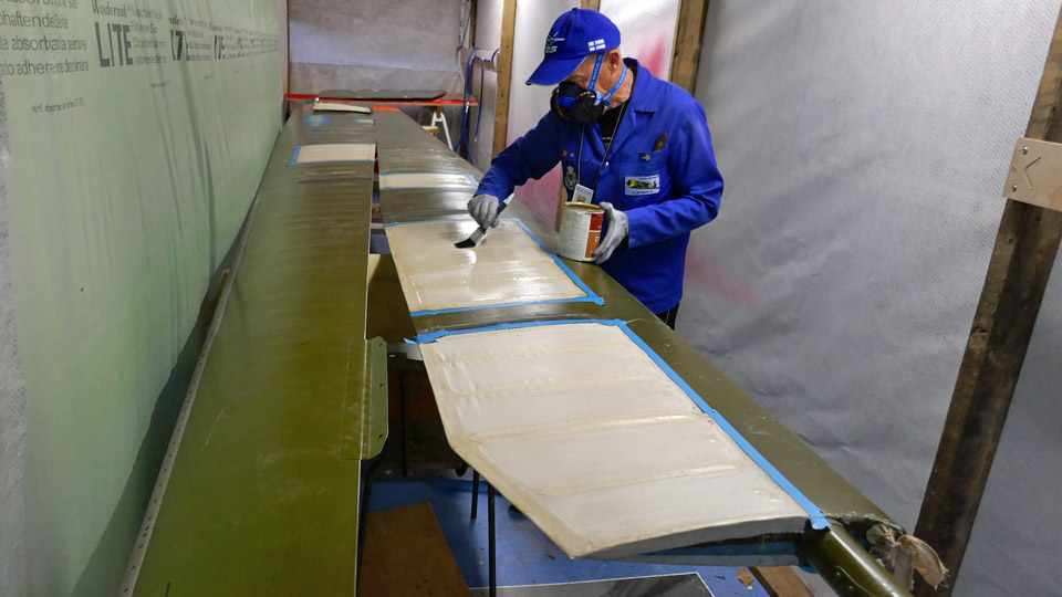
The patches on the upper side of the port wing were glued first. Nitrocellulose varnish was used for the gluing work. This kind of varnish is used also for tightening upholstery fabrics. It is necessary to wear effective protective masks during the varnishing work and there can’t be other ongoing activities in the restoration space of the Finnish Aviation Museum when varnishing is being done.
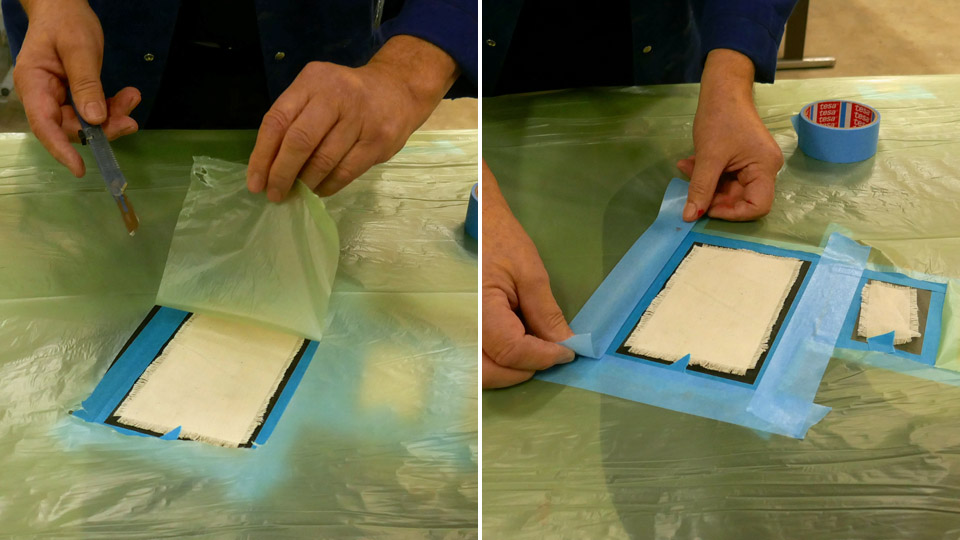
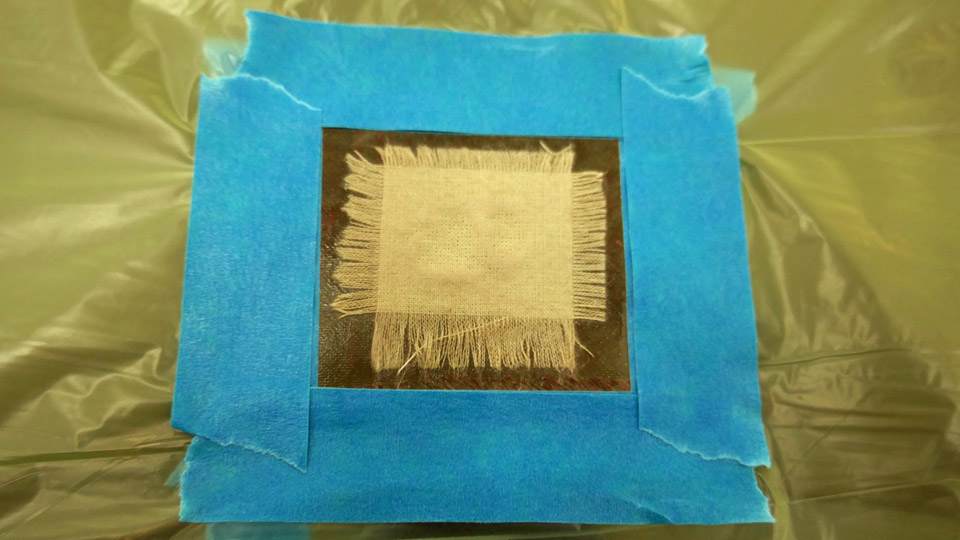
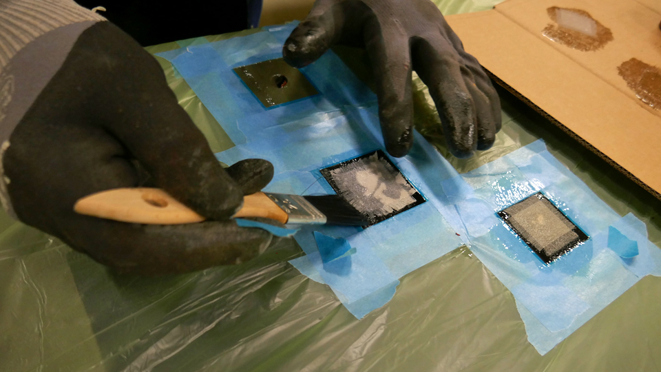
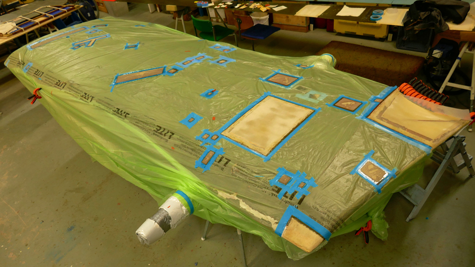
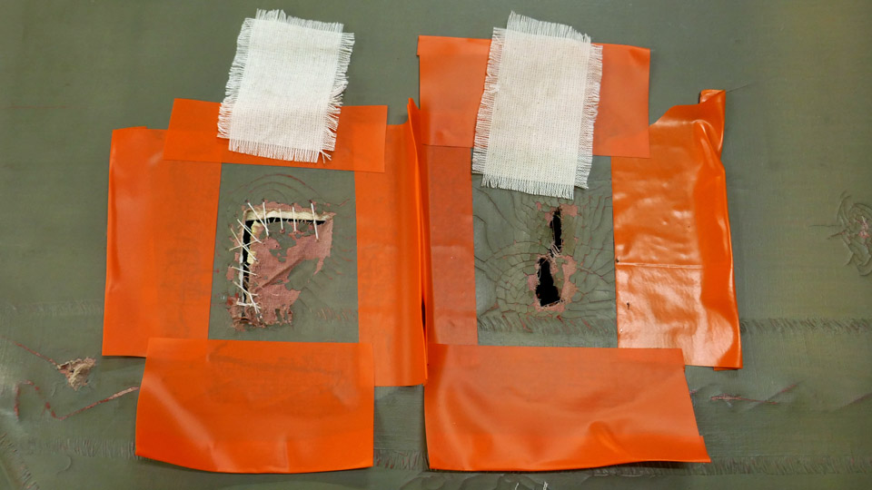
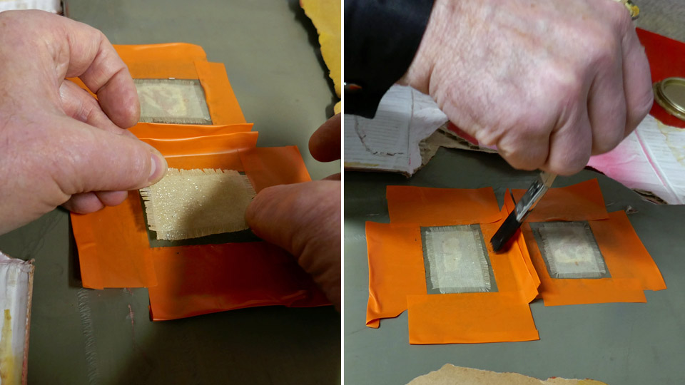
Before gluing the patches, each damaged area was surrounded with protective tape. The tape limits the work area and stops the gluing lacquer from seeping into the fabric covering outside the patching area. When all patch areas had been taped, a thing sheet of protecting plastic was spread on the wing. The plastic protects the fabric covering outside the work area when all the holes around the wing area are being varnished. A hole was cut in the plastic at each taped area. The edges of the protecting sheet were taped on the tape surrounding each work area. The wing was now well protected for the varnishing work.
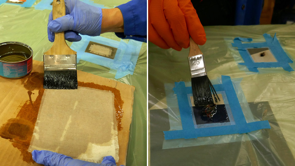
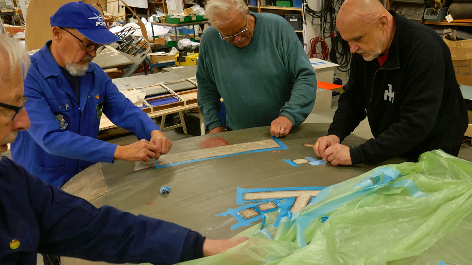
Half a dozen Tuesday Club members started gluing the patches on the wing. X-Speed nitrocellulose varnish was used. The first phase was to varnish the patches soaking wet while they rested on a sheet of corrugated cardboard. Then the areas surrounded with tape were varnished. The patches were not immediately moved into their places. It took about five minutes before the lacquer became drier and gluey. After a short while the patches were moved and pressed onto their corresponding repair areas. Another layer of lacquer was applied, and the brush was used to straighten the frayed edges of each patch.
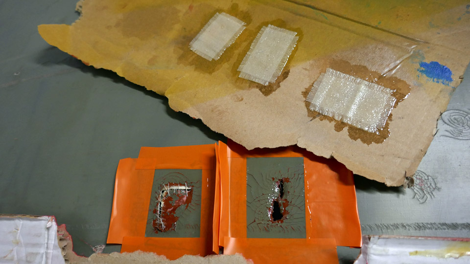
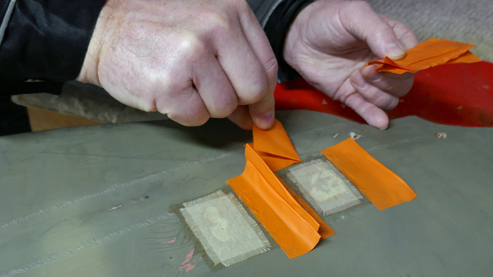
When all the patches had been fastened, the protecting sheet of plastic and the tapes around the work areas were removed. The Tuesday Club team used the gentle blue type of painter’s tape around the work areas, but it was noticed that the tapes have to be removed immediately after the varnishing is ready. If the tape stays on the old fabric for more than an hour, the tape may stick too tightly on the original painted fabric and when the tape is unfastened, it will leave a mark or, in the worst case, the original painted surface will be damaged.
When the 34 patches on the upper surface of the port wing had been glued into place, the same procedures were done on the 32 patches on the lower side of the wing. Now the 66 holes on the lower port wing had been patched.
When the patches had dried, the surfaces were honed smooth and varnished again. The varnishing and honing was repeated four times. Now the patches are ready to be painted, using paint which matches the original paint on the wing. The painting will not be done before the work on the lower starboard wing has reached the same phase. Photos: Lassi Karivalo. Translation: Erja Reinikainen. |
|
Avainsanat: aviation history, restoring, old aircraft, Caudron C.59, CA-50 |
Tuesday Club has started its 31th year with many activitiesMaanantai 10.2.2020 - Member of Tuesday Club
In the beginning of the year it is appropriate to summarise the activities of the Tuesday Club in the previous year. In the summer the Tuesday Club team finalized the restoration of the I.V.L. K.1. Kurki aircraft, after three years of work. The Kurki was assembled and placed on display at the Päijänne-Tavastia Aviation Museum in Vesivehmaa. As the Kurki-project had come to an end, a new project could be started: Caudron C.59 (CA-59) will be restored for display. The restoration of the VL Myrsky II (MY-14) was started six years ago and the Tuesday Club team worked on it in 2019 as well. The fourth project in the Tuesday Club was to repair the two broken rotor blades of the SM-1 helicopter. Also some additional minor tasks were given to the Tuesday Club team and the year was rather loaded with work. Over 7 000 work hours were done during the year. The team has continued with the ongoing tasks in the beginning of this year. Repairs of Caudron’s fabric-covered wings
The main tasks at the moment in the Caudron C.59 advanced trainer plane restoration project are the repairs of the holes and tears in the fabric covering on the lower wings. This is not a minor project, because there were 66 holes to mend on the lower port wing and about 50 on the starboard wing. It is very sad to see how badly the Caudron’s wings have been treated during the 90 years of storage.
The holes and tears on the lower port wing have already been repaired. The edges of the tears were connected with stitches and a fabric patch was glued on the sewn area. Nitrocellulose varnish was used for gluing the patches and it smoothed the repaired fabric when shrinking. Historical values have to be considered when the holes on Caudron’s wings are repaired. If the fabric covering of the wing had been damaged with over 50 holes when the aircraft was still in use, the whole wing would have been covered with new fabric. At the moment the Tuesday Club is working on the lower starboard wing. The fabric surfaces were cleaned and then the repairs of the holes could be started. In addition to the work on the wings, the repair of the horizontal stabilizer is going on. The horizontal stabilizer had to be dismantled to repair the damages and now it is being re-assembled. SM-1 helicopter’s rotor blades were repaired
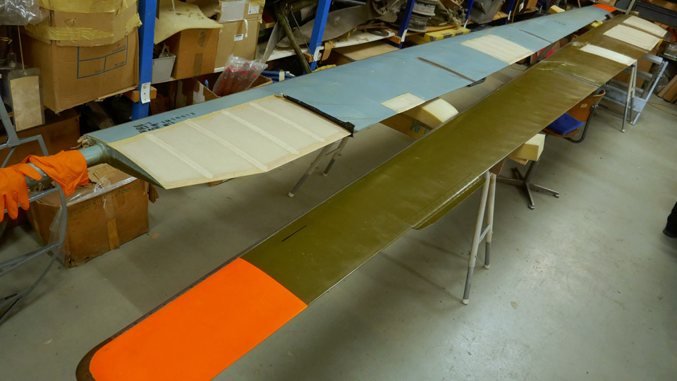
The repair work on the PZL SM-1SZ (HK-1) helicopter’s rotor blades was started a year ago. Now all the damaged areas have been repaired, i.e. covered with new fabric and treated with shrinking varnish. The damaged areas were located in the fabric-covered areas of the blades. Now the new fabric areas have been smoothed using nitrocellulose varnish and are waiting to be painted. When the original paint type and colours have been defined, the new fabric areas can be painted. The upper surface of the blade will be painted dark green and the lower side will be pale blue.
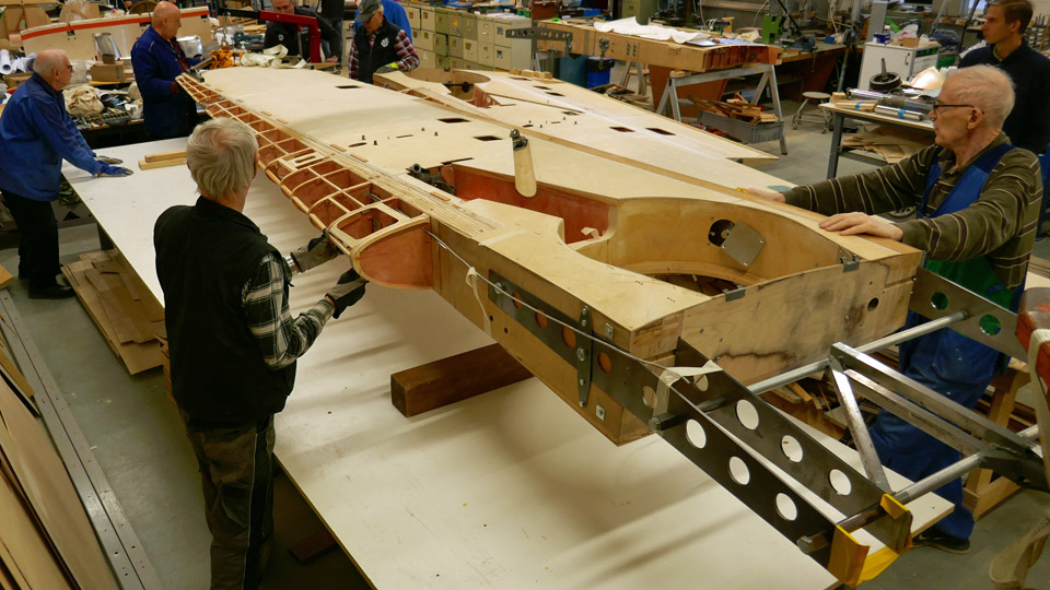
Myrsky’s restoration work continues for one more yearThe aim is to complete the restoration of Myrsky MY-14 in March 2021 when the aircraft will be placed on display. The schedule is tight, but the restoration teams are working hard in the Tuesday Club and in the Finnish Air Force Museum in Tikkakoski.
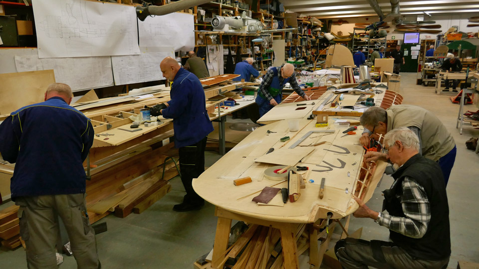
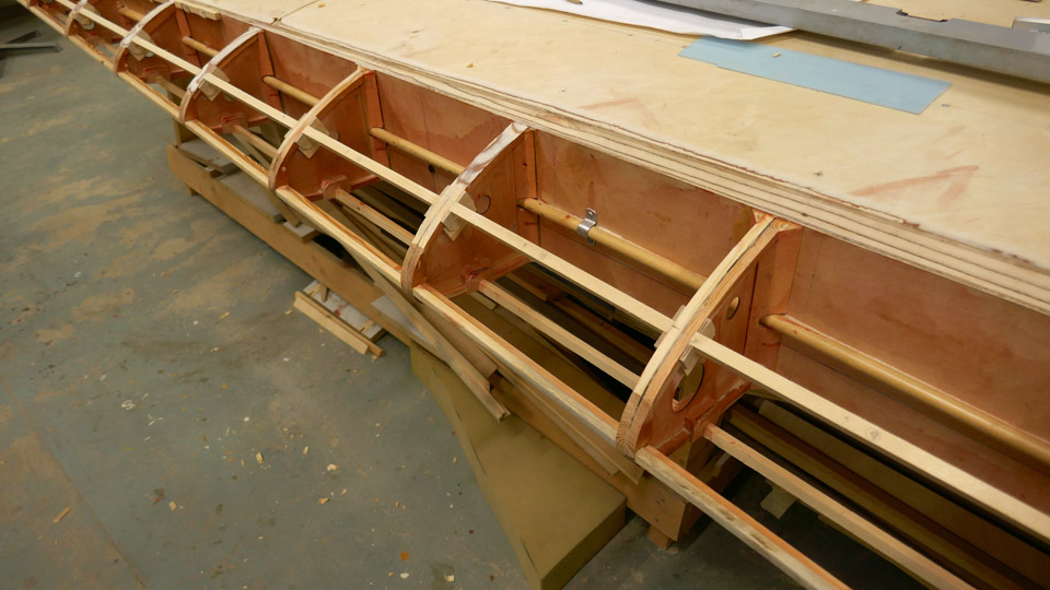
In the Tuesday Club the main emphasis is on the restoration of the two wing halves. Both wings are under construction in the restoration space at the Finnish Aviation Museum. The leading edge of the starboard wing has been almost covered with new plywood and the trailing edge area on the upper surface will be covered soon. The starboard wing will soon be ready for the surface preparations, which are needed before painting. The work on the port wing is about one month behind the starboard wing. There is still some work needed on the port wing before the flap compartment on the trailing edge is ready, the flap is completed and the leading edge is covered with new plywood.
Photos: Lassi Karivalo Translation: Erja Reinikainen. The repairs of the Caudron’s fabric-covered wings |
|
Avainsanat: aviation history, restoring, old aircraft, Tuesday Club |
Repairing tears in Caudron's (CA-50) fabric coveringMaanantai 30.12.2019 - Member of Tuesday Club
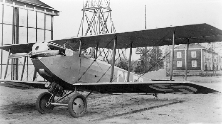
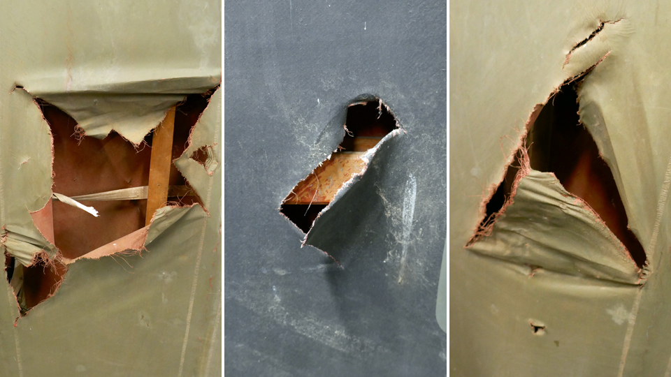
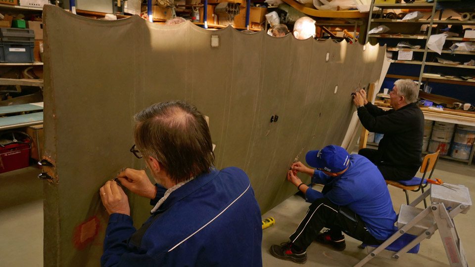
Caudron C.59. Photo: Wikipedia. The Caudron C.59 (CA-59) airplane, which is under restoration at the Tuesday Club, has several holes and tears in its fabric covering. The damage has happened during the 90 years of storage. All damages in the fabric covering will be patched using fabric patches, following original procedures.
There are several methods to repair the tears on the fabric covering. A thin strip of plywood can be glued under the fabric to support the tear and the edges of the tear are glued on this supporting piece of wood. A covering fabric patch is placed on top. If the damage covers a large area on the fabric covering, the damaged material can be removed and replaced with new fabric. This method can be used e.g. between wing ribs. In this blog we concentrate on how the tears and holes on Caudron’s fabric were repaired by sewing and using fabric patches on top of the stitched area.
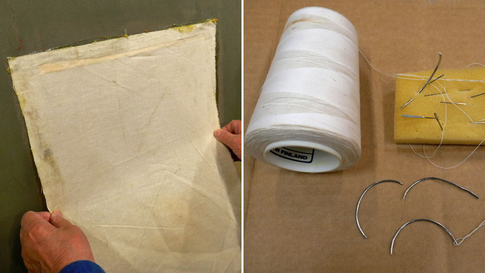
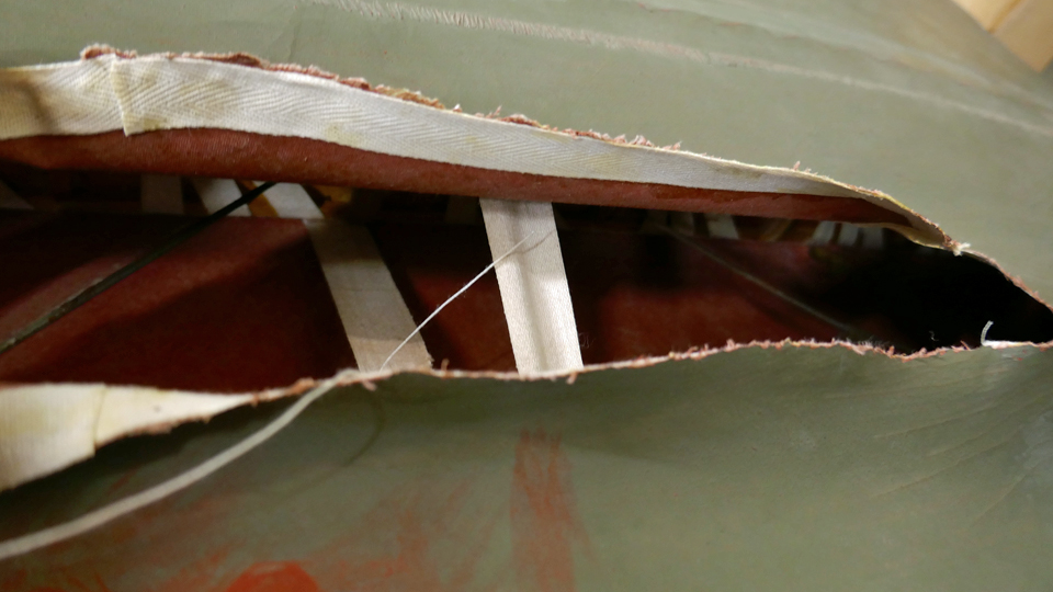
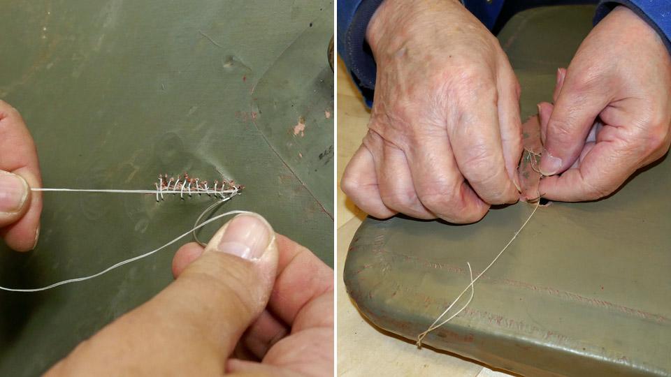
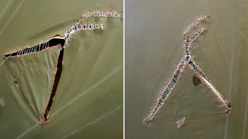
First the edges of the tear will have to be stitched against each other, or at least as close to each other as possible, by tightening the stitching thread. Then a covering fabric patch is glued on the tear. Small punctured holes can be covered with a patch without stitching first. The edges of the tear are stitched using a curved upholstery needle and thin linen thread.
Before the edges of the tear were stitched, a narrow strip of linen was glued under the edges to support the frayed covering fabric. The old fabric is so thin that it would be frayed even more when the edges are pulled together with the stitching thread. When the stitching progressed, the edges of the tear were pulled closer to one another by tightening the thread. Usually the original covering fabric has shrunk during the years and it is impossible to connect the edges of the tear.
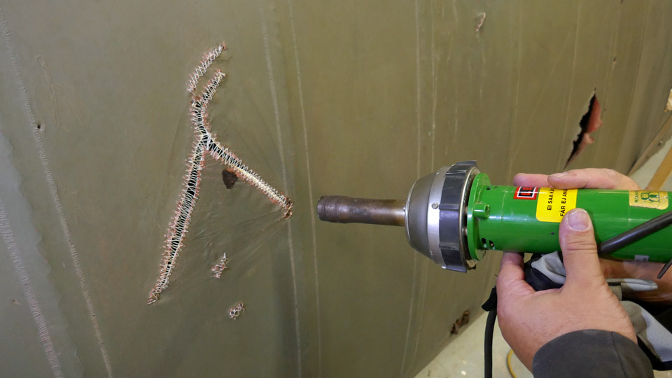
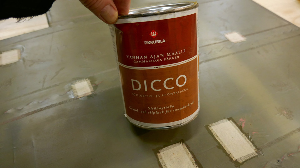
Then and now. After the stitching, the fabric in the repair area remains somewhat loose and wrinkled, in spite of tightening the stitching thread. Additional tightening can be done with a heat blower. The heat from the blower melted the old lacquered surface of the 1920s’ covering fabric and it became a little bit loose. When the lacquer cooled down, it shrunk, and tightened also the stitched area. Heat treatment is a useful method to tighten the stitched area before gluing a fabric patch on the damaged area. The fabric patches were glued on the stitched areas and punctured holes using traditional nitrocellulose lacquer. On Caudron’s patches Tikkurila Oy Dicco lacquer was used.
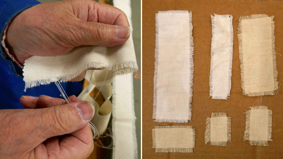
Suitable patch pieces were cut from cotton fabric. The edges of each patch were frayed manually before gluing so that the patch would fasten tightly on the repaired area. The fraying was done by unravelling the warp threads along 3-5 mm around the patch edges. This method was used already in the 1920s’, the edges on the strengthening fabric strips on the Caudron’s wing ribs have been unravelled in this manner. Nowadays special scissors are used when cutting the saw-toothed edges of a fabric patch or a fabric strip before gluing.
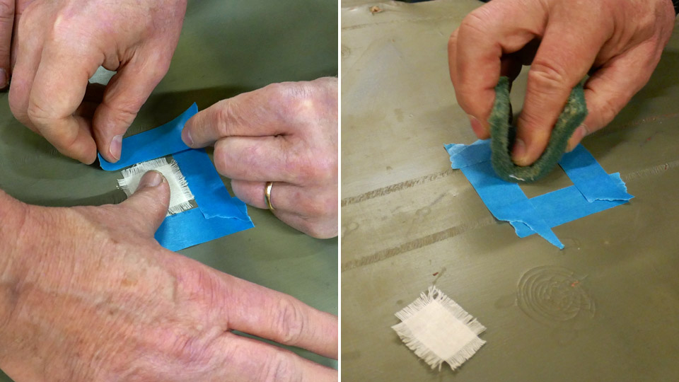
The damaged area on the original fabric was surrounded with protective tape, which was placed around the area before gluing the patch. It is necessary to limit the work area and to keep the gluing lacquer in the patching area, preventing it from seeping outside the area. The work area was buffed rough before gluing. The buffed dust and the grease on the fabric surface was removed using water-Sinol solution. Then nitrocellulose lacquer was spread on the work area and on the fabric patch, which was placed on a piece of cardboard. The patch was lacquered soaking wet.
It took about five minutes before the lacquer became drier and gluey. The fabric patch was carefully placed on the stitched work area. Another layer of lacquer was applied, and the brush was used to straighten the frayed edges of the patch. After about ten minutes the protecting tapes were removed, and the patching was ready.
The Tuesday Club team noticed that leaving the protecting tape on the work area for a longer time will cause problems. A “gentle type” of painter’s tape was used but the problem could be seen. The tape may stick too tightly on the original painted fabric and when the tape is unfastened, some original paint will peel off with the tape.
About two dozen holes and tears on Caudron’s port lower wing and tailplane and fin have been repaired, using the method described above. About a dozen holes still need patching. And there is more work ahead when the tears and holes on the starboard lower wing and both upper wings are repaired. Photos: Lassi Karivalo Translation: Erja Reinikainen. |
|
Avainsanat: aviation history, restoring, old aircraft, Caudron C.59, CA-50 |
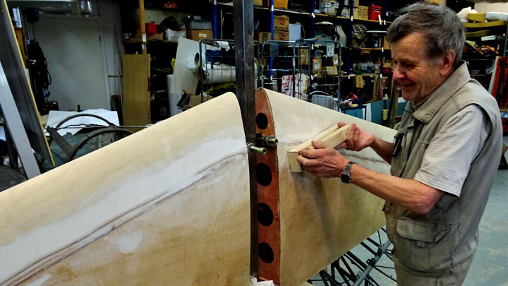
Experimenting dry plywood covering for leading edge on Myrsky's starboard wingTiistai 10.12.2019 - Member of Tuesday Club The restoration work of VL Myrsky II (MY-14) has progressed well during the autumn and the plywood covering on the starboard wing has been completed, excluding the leading edge. The plywood work on the leading edge has had to wait that the work on the port wing, which is being built alongside, reaches the point where the trailing edge is under construction. This is when the two wings under construction in the restoration space of the Finnish Aviation Museum change places. The wings will be moved from their first work platform on to the other platform. This is necessary in order to have enough working space around the wing to complete the port wing’s trailing edge and the starboard wing’s leading edge.
The leading edge of Myrsky’s wing consists of plywood ribs and supporting battens between the ribs. The leading edge is covered with 1,5 mm thick plywood. One sheet of plywood covers the surface of four rib-gaps. Four joining plywood sheets are needed to cover the whole leading edge, which is about five meters long. The plywood sheets are joined on a rib, using a scarf joint.
The challenge in the plywood covering of the leading edge is to bend the plywood sheet around the tapering leading edge. If the profile of the leading edge is very pointed, bending the dry plywood sheet around the edge will cause tears and cracks on the outer surface of the plywood. To prevent the plywood from cracking, the sheet is usually moistened or sometimes the wet plywood is fastened on a last, which models the leading edge. The plywood sheet will dry on the last and form a trough, which can be installed on the leading edge.
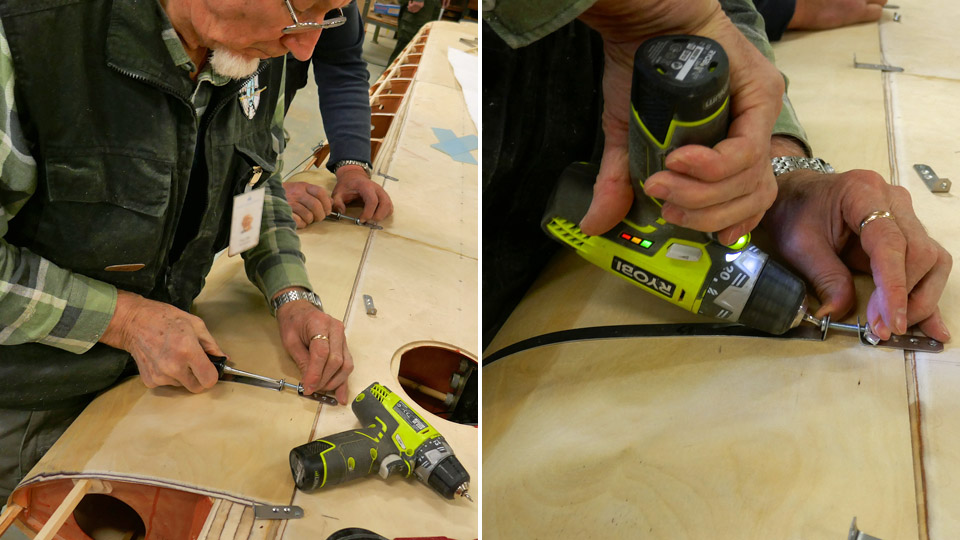
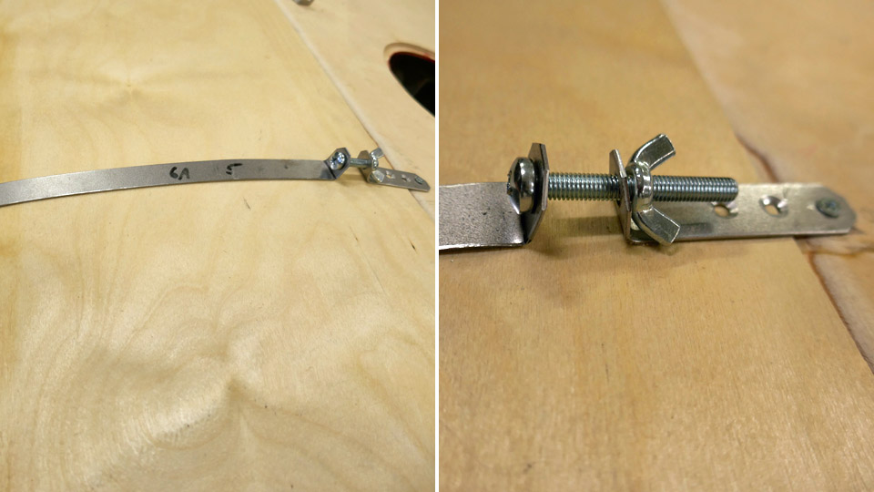
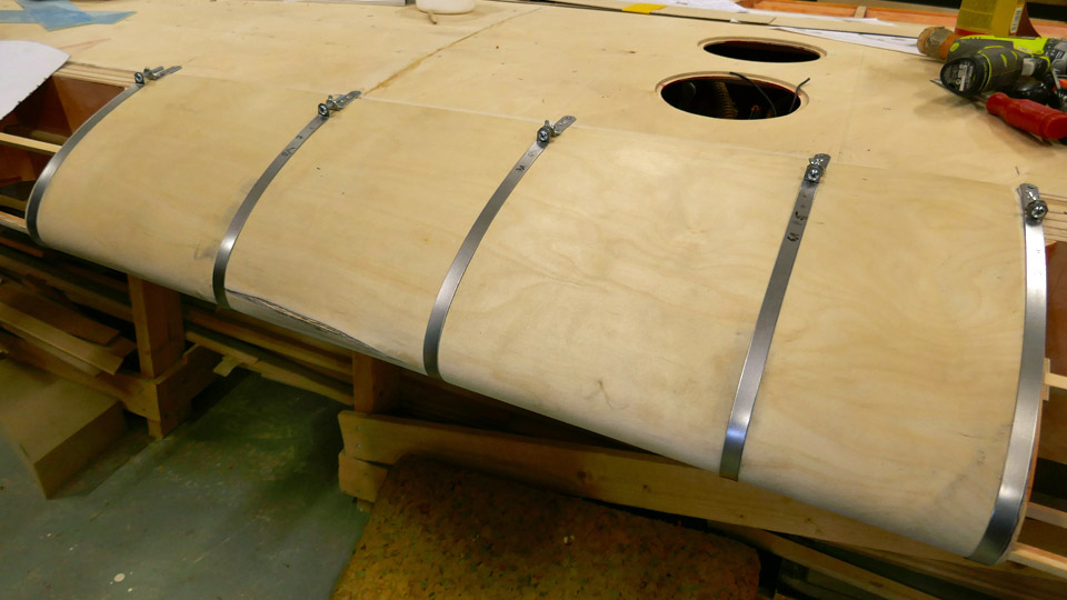
The Tuesday Club team wanted, however, to make an experiment and bend the dry thin 1.5 mm plywood sheet on the leading edge. The leading edge profile on Myrsky’s wing is not very pointed. For the experiment steel bands were made from 1 mm thick steel plate, they were cut 10 mm wide. The bands are used for pressing the plywood sheet evenly against the leading edge ribs. A steel band was made for each rib on the leading edge, corresponding the length of the leading edge profile. The bands were placed on each rib.
A tightening clamp was made at the upper end of each band, with a wing nut for tightening the band against the plywood. At the tightening clamp the ends of the band are bent to an angle of 90 degrees for the wing nut joint. The lower end of the band is fastened with a screw on the front spar on the lower side of the wing. The upper end of the band (with the tightening clamp) is fastened on the upper side of the wing on the wing spar.
The dry bending of the plywood covering was experimented without any gluing along the distance of four rib-gaps. The bands were fastened on their places on the five ribs, with the tightening clamps still open. A piece of plywood was cut from the 1.5 mm thick plywood sheet, matching the area of the four rib-gaps. The edges of the plywood sheet were bevelled so that the adjacent sheet can be joined with a scarf joint.
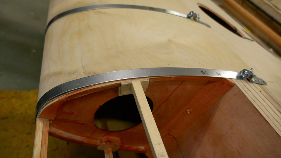
When the preparations for the experiment had been made, the plywood sheet was fitted, lower edge first, between the leading edge ribs and the tightening bands so that it reached the front spar on the lower side of the wing. Then the plywood sheet was pressed against the ribs, using the bands. When the sheet was in place, the clamps were tightened with the wing nuts. Now the plywood sheet was tightly pressed against the ribs.
The Tuesday Club team was annoyed when a crack in the plywood veneer sheet was noticed at the tip of the leading edge. This means that the experiment failed: dry plywood can’t be used when covering the leading edge on Myrsky’s wing. The 1,5 mm thick plywood sheet has to be moistened on its outer surface before it is pressed and tightened with clamps against the leading edge ribs. Photos: Lassi Karivalo Translation: Erja Reinikainen. |
|
Avainsanat: aviation history, restoring, old aircraft, VL Myrsky II, MY-14 |
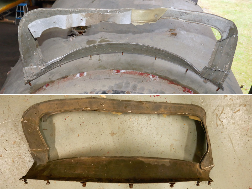
Repairing Caudron C.59 front cockpit's windscreenPerjantai 6.12.2019 - Member of Tuesday Club On Friday, October 11th some of the Caudron’s (CA-50) fuselage parts were dismantled in Vesivehmaa and brought to the Tuesday Club’s workspace. These items included the damaged aluminium frame of the front cockpit’s windscreen. The windscreen had been fastened on the plywood covering of the fuselage with seven bolts. The bolt nuts were easy to unfasten, but it was a challenge to unfasten the windscreen frame from the plywood, because the bolts were covered with a heavy layer of rust. A screwdriver was used as a lever between the windscreen frame and the plywood covering and finally the rusty bolts could be manoeuvred through the plywood.
The windscreen frame, originally made from thin aluminium sheet, had been badly bent and partly damaged. However, it can be straightened and repaired, and it can be installed back on the Caudron’s fuselage. There were fragments of the original windscreen still attached to the frame. The Tuesday Club team concluded that the windscreen had been made of celluloid, typically used in 1920’s airplanes. The celluloid window has been fastened with rivets between the windscreen frame and the aluminium profiles around the window.
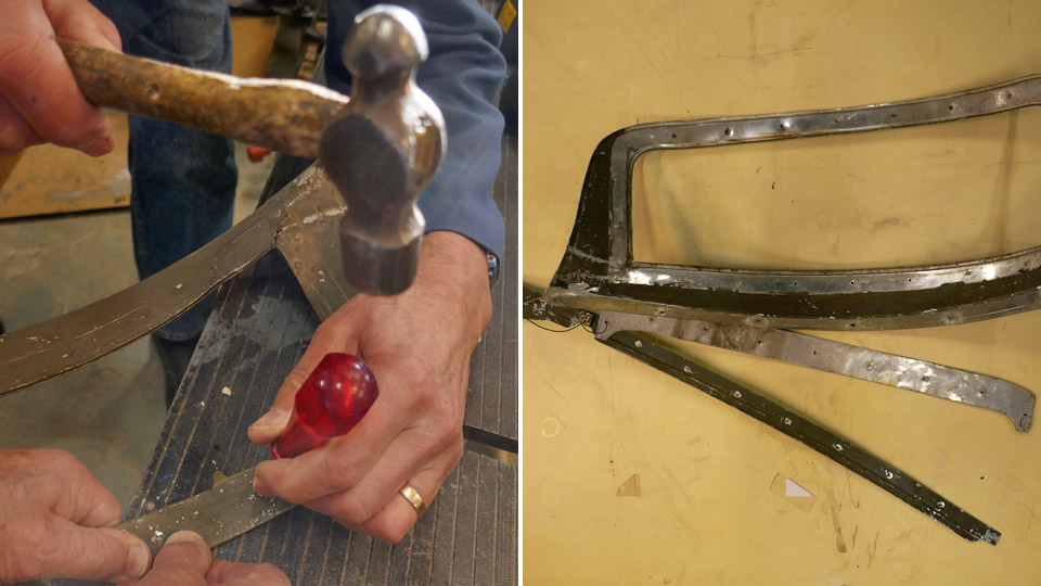
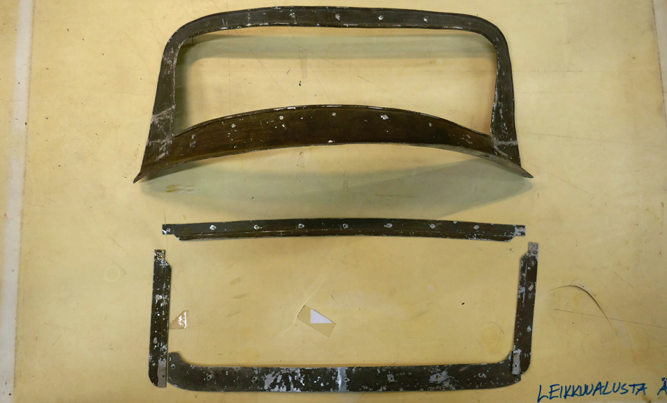
The repair work was started by unfastening the four aluminium profiles that surrounded the window. All rivets that had connected the windscreen frame and the surrounding profiles were unfastened using a spike. The original windscreen celluloid fragments were also removed. The bent windscreen frame was carefully hammered into its original shape. The aluminium profiles were also straightened. Then the new windscreen could be made.
The original windscreen windows had been made of 1 mm thick celluloid plate. Such material isn’t available anymore, so a modern polycarbonate plate in the corresponding thickness was used.
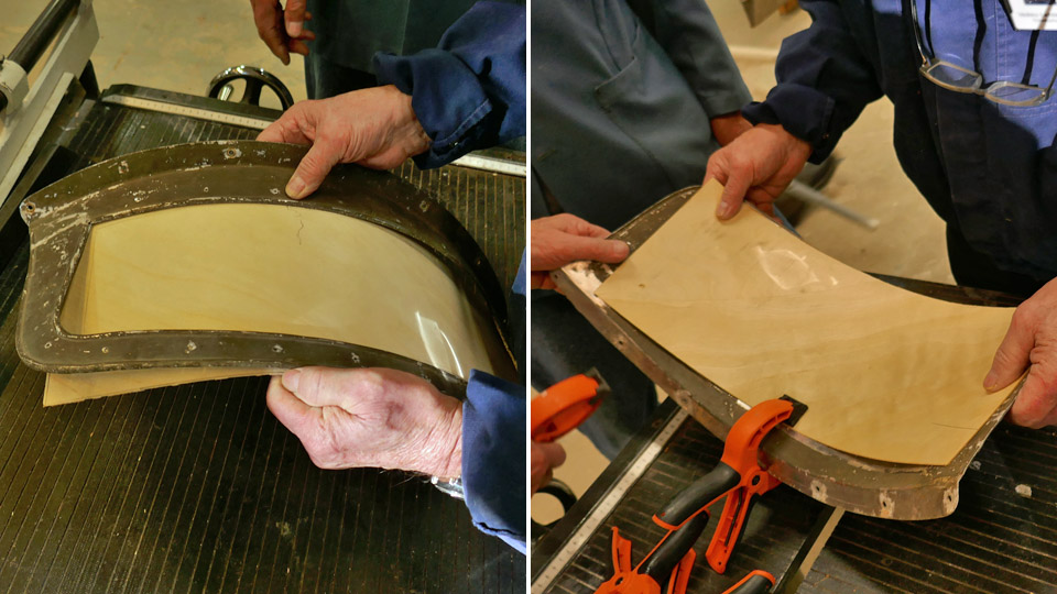
First a thin flexible piece of plywood was placed on the windscreen frame and the window shape was drawn on it. The pattern was used to cut the new window from the polycarbonate plate. The new window was cut a couple of centimetres larger than the pattern, in order to have enough material to shape the plate into the correct measurements. The polycarbonate plate was fitted into the windscreen frame, shaping it gradually. When the new window fitted properly between the frame and the surrounding profiles, preparations for the riveting were started.
The polycarbonate window was fastened between the frame and the surrounding profiles using strong clamps. Then the holes for the rivets were drilled through the plate, positioning them at the original rivet holes in the windscreen frame. When each hole had been drilled, a cleko-fastener was placed in it, using pliers. The cleko-fasterers were used to ensure that the window stayed in place and the rivet holes were in the correct positions. Hole by hole, the edge of the windscreen was fastened with clekos.
The polycarbonate window was riveted onto the frame, hole by hole, removing each cleko-fastener and putting a 1,5 mm long aluminium rivet into each hole. A compressed air hammer and a traditional hammer were used to hammer the rivets into place. When the riveting was ready, the Caudron C.59’s front cockpit window was ready. A protecting film still covers the window on both sides, the films will be removed when the windscreen has been installed into its place on the Caudron’s fuselage. The paint on the windscreen frame is worn and damaged, but the decisions about the surfacing of the frame will be made later.
The windscreen of the rear cockpit has been lost. At first the Tuesday Club team thought that the rear cockpit’s windscreen could be built using the front cockpit’s windscreen as a model. When the team studied the surface and the marks of the Caudron’s fuselage in Vesivehmaa more closely, it was discovered that obviously the rear windscreen had been significantly different from the one in front. Therefore it was decided that the rear cockpit’s windscreen won’t be made before the Caudron’s fuselage is moved from Vesivehmaa into the restoration space at the Finnish Aviation Museum. This will probably take place in 2021. Photos: Lassi Karivalo. Translation: Erja Reinikainen. |
|
Avainsanat: aviation history, restoring, old aircraft, Caudron C.59, CA-50 |
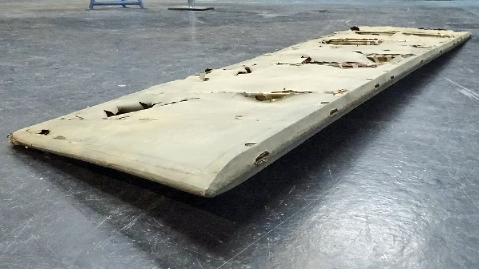
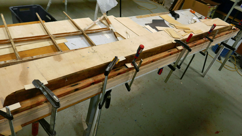
Caudron C.59's horizontal stabilizer is straightenedTiistai 19.11.2019 - Member of Tuesday Club During the 90 years of storage, the Caudron’s horizontal stabilizer has bent badly and it is also otherwise in such poor condition that it had to be dismantled for the restoration work. During the dismantling it became clear that the reason for the bending was the batten on the leading edge. The batten on the trailing edge was also slightly bent. Both battens had to be straightened before re-installing the stabilizer parts and the fabric covering. The team decided to try and straighten the battens by making them thoroughly wet and then fastening them on a level table top to dry and straighten.
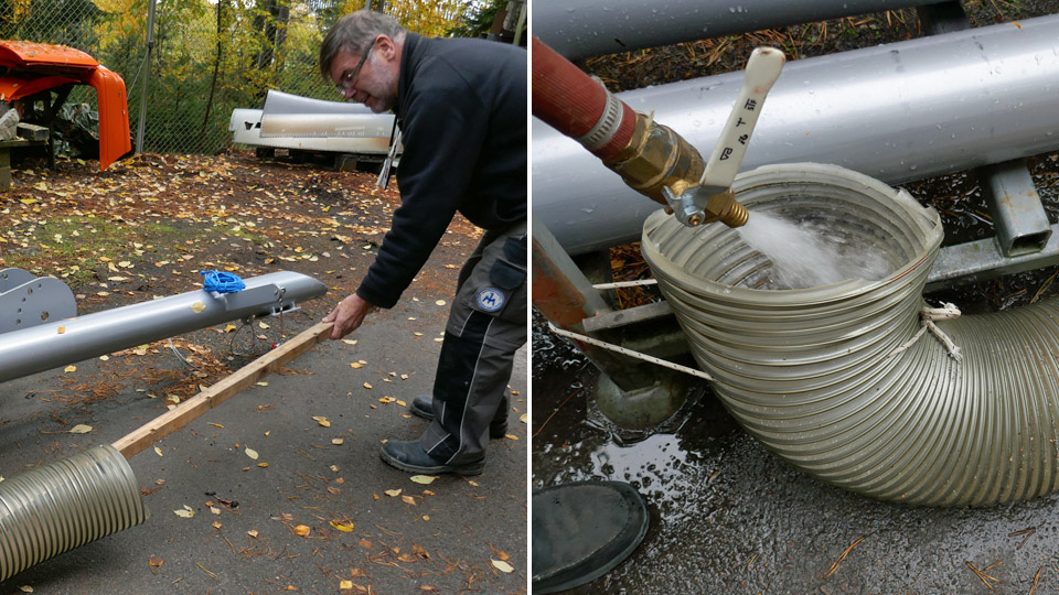
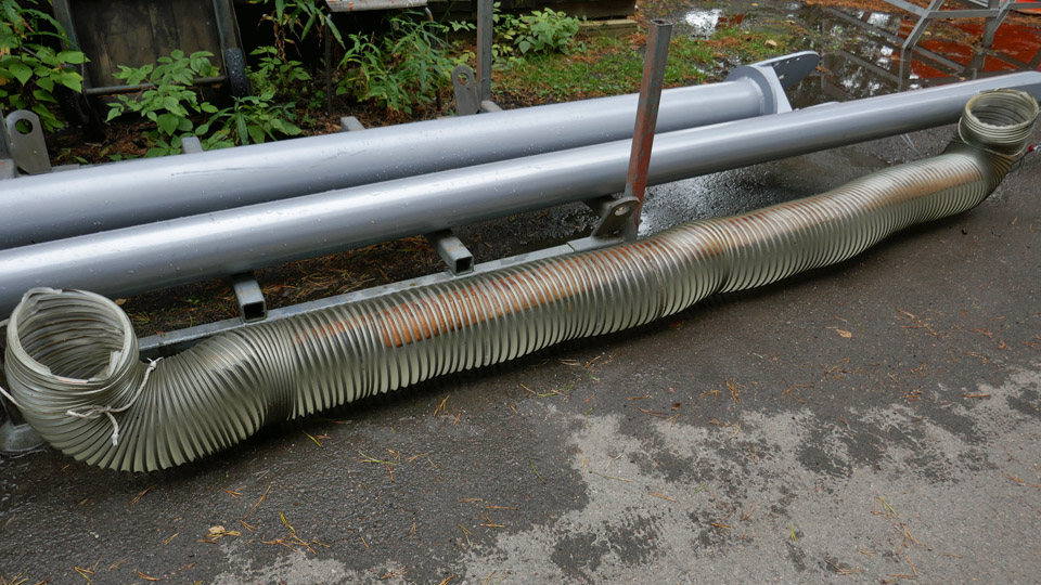
Some flexible ventilation duct was found in the storage of the Finnish Aviation Museum and this duct was used to make a container for soaking the leading and trailing edge battens. A four meters long piece of duct was needed for the battens which are nearly three meters long. When the battens had been placed inside the duct, the ends of the duct were bent upwards and the duct “tub” was filled with water. The team estimated that it would take about a week for the battens to get thoroughly soaked when they were submerged in water.
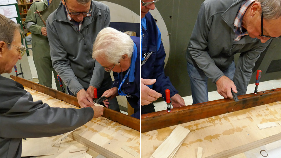
The battens were taken out from their bath after a week, and it seemed that both battens had already straightened by themselves. Obviously wood returns to its original shape when it is thoroughly soaked, in this case to the shape which had been made for the horizontal stabilizer. However, the leading edge and trailing edge battens were fastened on a heavy table surface using clamps. There the battens could dry and hopefully regain their correct shape.
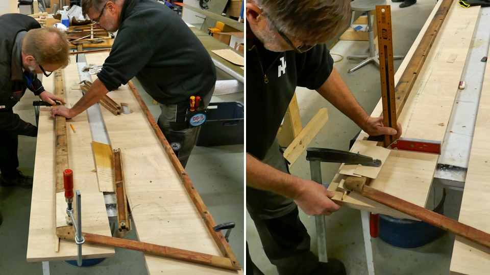
After another week the clamps were unfastened, and the team found out that the battens were dry and almost straight. The thinner trailing edge batten was completely dry but the leading edge batten felt damp and it was still a little bent. The team re-fastened the leading edge batten on the table with the damp side upwards. In the following week the batten was unfastened and the whole horizontal stablizer frame (leading and trailing edge battens and the end battens) was assembled and placed on the table. The team noticed that the leading edge batten was still slightly bent and the whole frame rose 3 cm up from the table top at its starboard rear corner instead of being flat against the table top.
The team decided to soak the leading and trailing edge battens for another week. Also the end battens were placed in the tub because they were a couple of centimeters bent inwards. After a week the battens were taken from the tub and this time they were fastened on the table as a frame. In the assembly work the leading edge batten was pushed straight using wedges. The aim was that when the leading edge batten dries when assembled in the frame, it would not bend back into its previous shape.
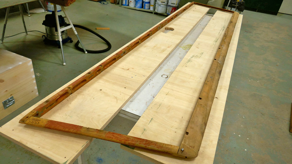
Another week went by and the frame was unfastened. The team noticed that again the frame was not flat but the rear corner of the frame rose slightly from the table top. The leading edge batten was still damp on the side which had been against the table. Therefore the leading edge batten was fastened on the table once more and left to dry for two weeks.
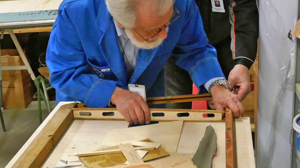
After two weeks the horizontal stablizer’s leading edge batten was unfastened and the trailing edge batten and the end battens were assembled. The team was delighted to see that the frame rested flat on the table – the leading edge batten wasn’t bent any more. Now the repaired ribs could be preliminarily tested between the leading and trailing edge battens. The Tuesday Club team had worked hard to return the battens to their original shape and succeeded. Photos: Lassi Karivalo Translation: Erja Reinikainen. |
|
Avainsanat: aviation history, restoring, old aircraft, Caudron C.59, CA-50 |
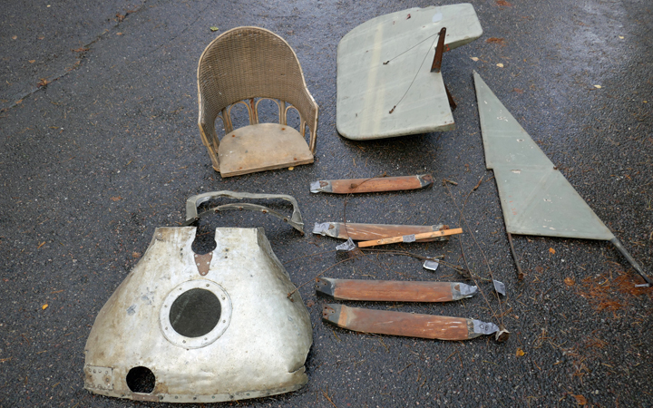
Parts of Caudron C.59 were transported from VesivehmaaMaanantai 4.11.2019 - Member of Tuesday Club The Tuesday Club has been working on the Caudron c.59’s (CA-50) horizontal stabilizer, both elevators, the wing struts and one lower wing. As there is no major work to be done on these parts of the plane, the team decided to go and fetch some more parts of the Caudron’s fuselage, which is still in the Päijänne-Tavastia Aviation Museum at Vesivehmaa. The Vesivehmaa museum was visited by about ten Tuesday Club members.
As soon as the team arrived in Vesivehmaa, the work was started and the vertical stabilizer, rudder and the bracing wires were unfastened and carried into the car in no time. All the parts fitted well into the spacious boot of the Skoda Octavia.
It took much longer to dismantle the wing struts which were on top of the front fuselage. Each strut bracing had rusted badly. CRC was used to unfasten the rusty bolts and fortunately the team managed to unfasten without damages all the bolts, three on each strut. Also the bracing wires fastened on the bracings were taken along. Furthermore, the aluminum sheet cowling on the engine mounting, the front cockpit seat and the badly damaged windscreen frame were dismantled to be taken to the Tuesday Club work space.
Left photo: Ari Aho. The engine cowling came off easily, as did the front cockpit seat, fastened on the frame with four bolts. More effort was needed to unfasten the damaged front windscreen frame. The frame had been fastened through the plywood covering using eight bolts, which had rusted badly. The nuts below the plywood covering were easy to unfasten, but to maneuver the rusty bolts through the plywood and the frame was challenging. The frame is very bent and there are still some remains of the original celluloid plexiglass on it. There are still several other pieced to be dismantled from the Caudron’s cockpit, e.g. the rear cockpit seat, the control column and the rudder pedals, but more time is needed to do all this.
While the rest of the team was working on the Caudron, a couple of Tuesday Club members installed the securing pins on the bolts of the I.V.L.K.1 Kurki landing gear and wing struts. The Kurki restoration work has been completed and the plane was returned to the Vesivehmaa hall in June.
The following parts of the Caudron C.59 (CA-59) were dismantled and transported from Vesivehmaa to the Tuesday Club hall:
When the team returned to the Aviation Museum in Vantaa, all items were carefully labelled and the smaller parts (such as the nuts and bolts of the wing struts) were stored in plastic bags to wait for cleaning. Photos: Lassi Karivalo except one separately credited Translation: Erja Reinikainen. |
|
Avainsanat: aviation history, restoring, old aircraft, Caudron C.59, CA-50 |
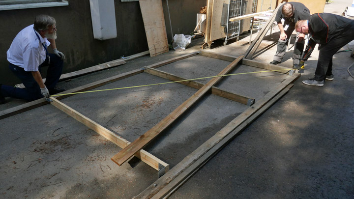
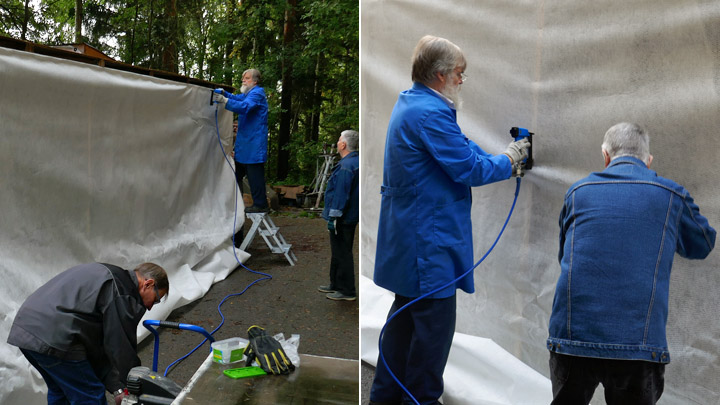
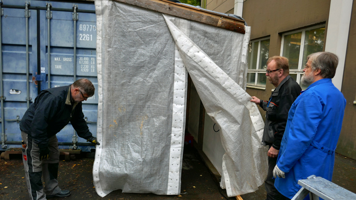
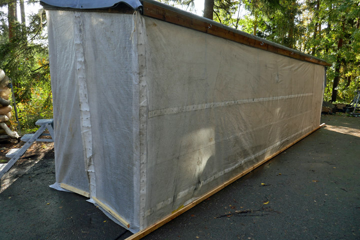
Painting shed was built behind Finnish Aviation MuseumPerjantai 11.10.2019 - Member of Tuesday Club Painting work in the restoration space in the Finnish Aviation Museum is not desirable or healthy because of the paint and lacquer fumes. Painting work is necessary in the restoration work and shrinking dope is used when finishing the fabric covers on the wings. At the moment e.g. the repaired rotor blades of the SM-1/MI-1 (HK-1) helicopter are waiting to be lacquered and painted. Soon also the tail parts of Caudron C.59 (CA-50) will need paint and lacquer. For these purposes a light painting shed was planned next to the storage container on the museum yard. The shed has walls, but it is not meant to be used in winter. However, with recirculation heaters painting work in the shed will be possible until late autumn. The shed was designed to be 10 meters long, 1,8 m wide and 2,1 m high. The length was determined by the long SM-1 helicopter rotor blades, which will be painted in the shed. The shed was designed so that the storage container forms one wall for the shed and the other long wall has a wooden frame made of 50x100mm timber. This frame is covered with non-woven fabric and tarpaulin. The roof is built of plywood sheets, placed on wooden roof beams and covered with a tarpaulin as a rain cover. All joints are made using screw plates. One of the principles for the shed was that it should be built, as far as possible, using material which can be found on the museum yard and storage. This is how the construction costs would be low.
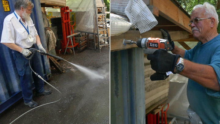
The work was started by cleaning the asphalt yard with a pressure washer where the shed will be built. Then a 50x100 mm wooden beam was fastened on the upper edge of the storage container’s wall. This beam will carry the weight of the roof structure. Then horizontal wooden beams were fastened on the asphalt, at a distance of 180 cm from the container wall, covering the length of the container. This will be the bottom of the wooden wall frame. The wall height is 210 cm from the top of the base beam.
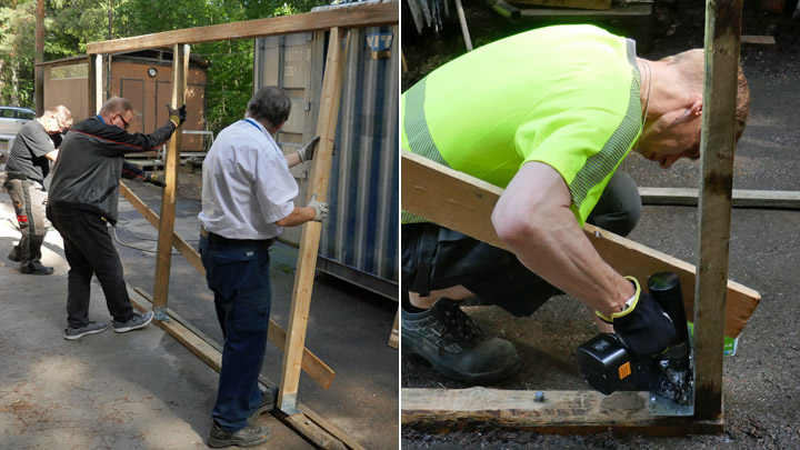
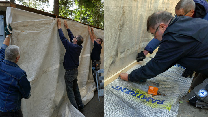
The wall frame was built in two parts. Both parts were assembled on the ground and then lifted upright and placed on top of the base beam. Wooden battens were used to support the upper edge of frame from the beam on the container wall. Then the frame was anchored in place on the base beam using angle irons.
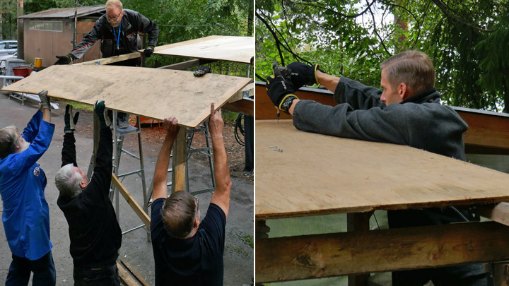
When the wall frame was standing firmly, the wooden roof framework was built from 50x100 mm beams which were fastened on the wall framework and the beam on the container. As the roof is 180 cm wide, two plywood sheets were needed to cover the width, one full sheet (120 cm) and a half sheet (60 cm). Suitable 20 mm thick and 120 cm wide plywood sheets were found at the museum. A part of the sheets was cut in half (60 cm wide). The plywood sheet pairs (full and half) were placed on the roof structure and fastened on the beams and onto the upper edge of the wall structure.
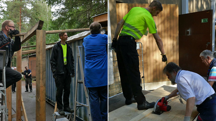
Then the wall frame was covered. A non-woven fabric, which will allow air to flow through, was stapled on the frame. Non-woven fabric was chosen because it is essential to have good ventilation in the painting shed.
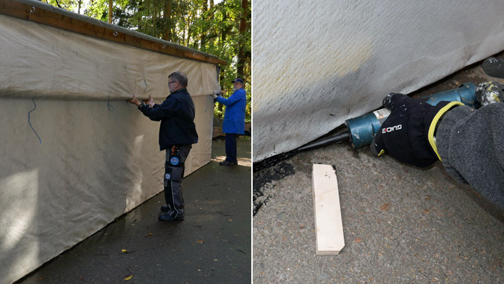
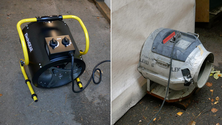
The ventilation will be boosted using fans. A tarpaulin was installed on the outside to protect the inner fabric from rain. The tarpaulin was fastened by its upper edge on the upper edge of the wall, otherwise it hangs freely. The tarpaulin can be rolled up and fastened on the upper corner of the wall when the shed is in use. A wooden batten was attached on the lower edge of the tarpaulin to keep it hanging straight and against the non-woven fabric on the inside. The seam between the base beam and asphalt was sealed using Sikaflex so that rain water running along the asphalt will not flow under the beam and into the shed.
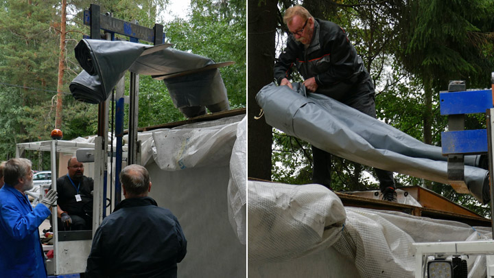
A heavy tarpaulin was assembled on top of the plywood roof to keep out the rain. The tarpaulin was lifted to the roof with a fork lift. The back end of the shed was covered with non-woven fabric and a tarpaulin was placed on the outside.
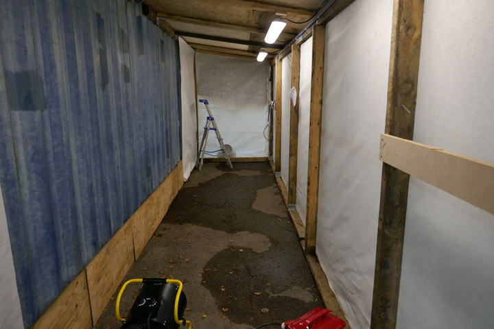
The last phase was to build a door to the front end of the shed. The door was built from two overlapping pieces of tarpaulin. The tarpaulins were fastened on a plank by their upper edge. The plank can be easily unfastened from the upper edge of the doorway when large painting items are brought into the shed and an unblocked doorway is needed.
The museum bought led lights (which were fastened on the upper corner of the wall) and an effective recirculation heater. When the heater was tested a temperature above 20 degrees was reached and the humidity in the shed decreased into readings which are required when painting or lacquering work is done.
The painting shed is now ready for use. Photos: Lassi Karivalo Translation: Erja Reinikainen. |
|
Avainsanat: aviation history, restoring, old aircraft, Tuesday Club |
Plywood covering on the lower surface of Myrsky's port wing is readyTorstai 19.9.2019 - Member of Tuesday Club The covering of the lower surface of Myrsky’s (VL Myrsky, MY-14) port wing has been finished in the area between the wing spars. Three sheets of plywood have been installed, starting from the wingtip, and the area around the landing gear is ready as well. As the upper surface has earlier been covered with plywood, the following work phase will be the construction of the flap space on the trailing edge. Also, the leading edge in front of the front spar will be covered.
Pieces from 3 mm thick plywood sheet were cut diagonally to cover the remaining area of the wing. Several holes, large and small, were drilled into the plywood sheet which covers the area around the auxiliary fuel tank / bomb rack. The holes are needed for the equipment on the rack and as operation hatches. The small plywood sheets were shaped to match the shapes of the landing gear and wheel wells.
When the lower surface of the wing will be covered, as it was on the original Myrsky, the plywood will cover the structures of the wing and the equipment inside the wing (such as the auxiliary fuel tank / bomb rack and the operation mechanisms for the ailerons and landing gear). In a way it is a pity that the complicated wing structure and the interesting mechanisms will disappear from sight and the future museum visitors won’t be able to see them. Fortunately, the Myrsky’s test wing (a 2,5m long piece of the wing) has been built during the project and will be partly covered with transparent plexiglass. On the test wing the structures inside the wing, the landing gear, bomb rack and other equipment can be seen.
When the last sheets of plywood had been cut into shape and tested in place, the inner surfaces were painted using polyurethane lacquer tinted red. Then the edges of the plywood sheets were beveled for the lap joints.
The plywood sheet in the bomb rack area was fastened first. Before gluing, the holes for the screws were drilled on the plywood sheets. Screws will be used to secure the glue joints. Flathead screws are used and the matching beveling was drilled on the plywood sheets. Then the glue was spread.
Epoxy glue was used when gluing the plywood sheets on the wing spars. Erikeeper Plus wood glue was used on the battens between the ribs. The sheet of plywood was pressed against the glued surfaces. The plywood sheet was secured in the right position, using a nail at each corner of the sheet.
When the screws had been fastened on the joints, the gluing on the front and rear spars was secured using 10 mm nails. Finally, a thick strip of plywood was placed on top of the lap joint of the plywood sheets.
When this sheet of plywood had been fastened, a couple of smaller plywood pieces were glued into place in the landing gear area. Now the lower surface of Myrsky’s port wing had been covered in the area between the spars. The wing looks like a wing now! Photos: Lassi Karivalo Translation: Erja Reinikainen |
|
Avainsanat: aviation history, restoring, old aircraft, VL Myrsky II, MY-14 |
Plywood covering on lower side of Myrsky's port wing is under wayTorstai 12.9.2019 - Member of Tuesday Club The covering of the lower side of Myrsky’s (MY-14) starboard wing was finished in early autumn and the work on the port wing could be started. The lower side between the wing spars will be covered with plywood. On the trailing edge side of the rear spar the aileron and flap will be assembled. The leading edge in front of the front spar will be covered later.
Pieces from 3 mm thick plywood sheet were cut diagonally to cover an area at the tip of the wing. These sheets are placed on the area between the spars to cover the area between 10 ribs, starting at the wingtip. One more sheet of plywood will be needed before the whole lower side of the wing is covered. The edges of the cut sheets were beveled for a lap joint and the lower side was protected against moisture using lacquer tinted red.
Screws will be used to make sure that the plywood is pressed tightly against the ribs and the supporting battens between the ribs. The holes for the screws were drilled on the plywood sheets. Three screws per batten between the ribs were used. Flathead screws are used and the matching beveling was drilled on the plywood sheets. Before gluing the correct positioning of the plywood sheets was ensured.
Epoxy glue and Erikeeper Plus glue was used when gluing the plywood sheets into place. Erikeeper Plus wood glue was used on the battens between the ribs.
Then the screws were fastened. A screw was placed into each hole, then a cordless screwdriver was used to fasten them through the plywood into the battens between the ribs. The work was finalized using a manual screwdriver so that the screw heads were about one millimeter below the plywood surface. The indentations on the surface will be covered and coated later.
The gluing of the plywood sheet edges on the front and rear spar was not secured with screws but using staples. The staples were “shot” on the plywood through small protecting pieces of plywood so that the surface of the plywood is not damaged. The proper fastening of the staples was secured using a hammer. When the glue has dried the protecting pieces of plywood and staples will be removed.
Finally, a thick strip of plywood was placed on top of the lap joint of the plywood sheets. Clamps were used to secure the strip and a metal weight was placed on top of the strip. Now the lower surface of the port wing had been covered from the wing tip as far as the auxiliary fuel tank / bomb rack. The plywood sheet covering this area is already under work. Photos: Lassi Karivalo Translation: Erja Reinikainen. |
|
Avainsanat: aviation history, restoring, old aircraft, VL Myrsky II, MY-14 |
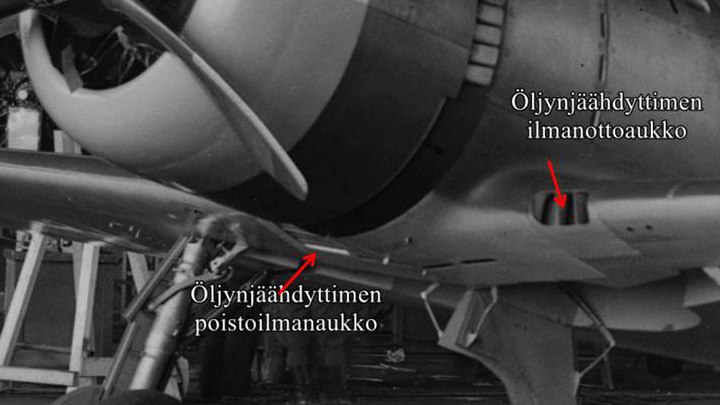
Ducts for Myrsky's oil cooler are builtLauantai 7.9.2019 - Member of Tuesday Club Myrsky’s Pratt & Whitney R-1830 Twin Wasp engine has a barrel-shaped oil cooler, similar to those on the DC-3 Twin Wasp engines. The motor oil is cooled, using air which flows through the cooler. At one end of the cooler there is a horn-shaped duct for supply air and at the other end a horn for exhaust air. Both ducts have a very complicated shape. The cooling supply air intake is at the leading edge of the port wing root. The exhaust air is lead out under the fuselage through an opening in the front fairing at the wing root.
(Öljynjäähdytin = Oil cooler, poistoilma-aukko = exhaust air vent, ilma-aukko = cooling air intake vent). The air flow to the oil cooler is controlled using the three parallel dampers inside the supply air duct. When all dampers are closed, they shut off the air flow to the cooler. By adjusting the dampers, the pilot can control the air flow to the oil cooler and the engine oil temperature.
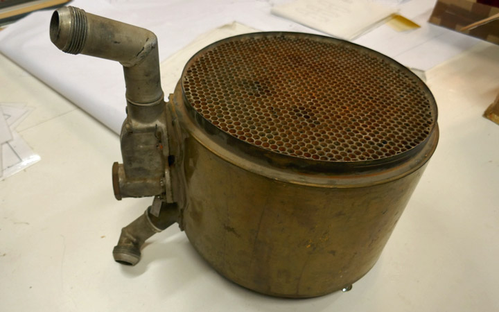
The Tuesday Club team was surprised to find an oil cooler for a Pratt & Whitney R-1830 Twin Wasp engine on the shelf of the working space in the Finnish Aviation Museum. The museum gave the oil cooler to be installed on the MY-14 engine, which was greatly appreciated. When an oil cooler was available, the work on the supply and exhaust air ducts could be started.
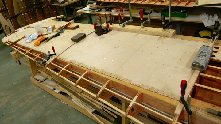
There are no original oil cooler ducts for Myrsky, so all parts will have to be reproduced. The work was started by building a part of the supply air duct which connects to the left end of the cooler. Myrsky’s original drawings were used to make a horn-shaped wooden last. One end of the last is round in diameter, matching the shape of the barrel-shaped oil cooler. The other end of the last is square is shape, matching the shape of the supply air duct’s other end.
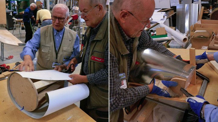
First a sheet of cardboard was wrapped around the wooden last so that a cardboard pattern can be made and used to cut a suitable piece from 1 mm thick aluminum sheet. The appropriate piece of aluminum sheet was cut, and it was bent around the last with tightening straps. The aluminum sheet was bent to match the duct shape. When the semi-finished duct was unfastened from the last, its edges were fastened to each other with rivets. The final phase was to cut the ends of the duct to the right shape, matching the last, and honed smooth. The first part for the supply air duct was ready.
Another similar supply air duct part was made for the display object, which will be built around the fuselage frame of MY-5. A four-meter long test wing is being built during the restoration process and this test wing will be fastened on the MY-5 fuselage frame. The aim of this partly restored MY-5 is to illustrate what the inside of the Myrsky looks like. The fuselage frame will not be covered, and the test wing will be partly covered using transparent plexiglass.
While the supply air ducts for the oil cooler were being made, also the work on the control dampers was started. The leader of the Myrsky-project, Mr. Matti Patteri, programmed the shape of the dampers on a laser cutter, using original drawings. The dampers were laser cut at ProLaser Oy and they have been sent to the Tuesday Club and are waiting for further activities. Photos: Lassi Karivalo except historical photo: The Finnish Avitation Museum's photo archive. Translation from Finnish to English: Erja Reinikainen. |
|
Avainsanat: aviation history, restoring, old aircraft, VL Myrsky II, MY-14 |
Caudron's wing struts are cleanedPerjantai 30.8.2019 - Member of Tuesday Club Caudron’s eight wing struts were brought from Päijänne-Tavastia Aviation Museum in Vesivehmaa to the Tuesday Club to be restored. The struts are made of wood and have a lacquered surface. The front struts are slightly heavier than the rear ones. All struts are in surprisingly good condition.
Each strut has a fabric covering at the ends, covering about 10 cm and painted using black lacquer. There are also metal insets at the ends, with hinged metal bayonets for fastening the struts on the wings. The struts are fastened by pushing the metal bayonets through the wings and locking the bars into place using castle nuts on the other side of the wing.
The restoration of the wing struts was started by cleaning the lacquered wooden surfaces and black end parts using mild dishwashing liquid. The work was finalized by wiping the surfaces with cloths dipped in clean water.
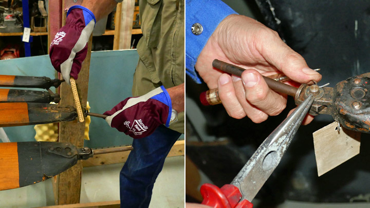
The metal insets and fastening bayonets were cleaned of dirt and rust. The hinged bayonets were unfastened to make cleaning easier.
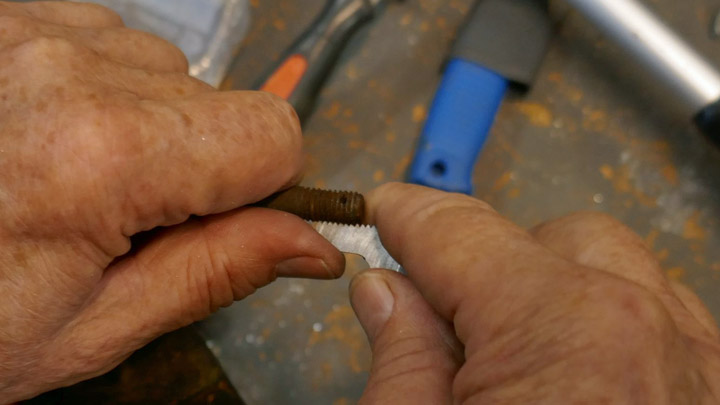
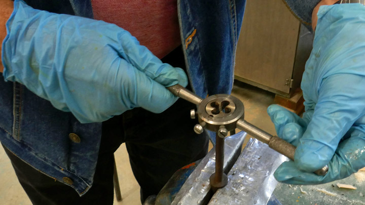
The screw thread at the ends of the bayonets were in poor condition because of rust. The diameter of the bayonet and the thread pitch were measured, the bayonet is 8 mm in diameter and the pitch is 1,5. The thread was opened using a suitable thread cutter from the cutter die.
There is still some work ahead before all 16 strut fastener bayonets have been cleaned. One of the original castle nuts is available, the other 15 will have to be bought.
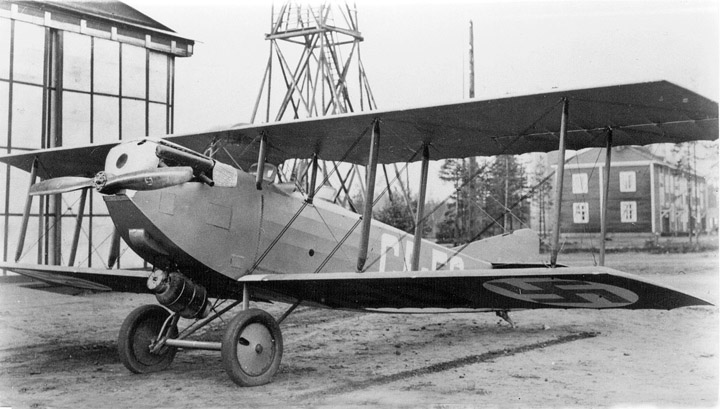
A historical photo from the Finnish Aviation Museum's photo archive shows what kind of aircraft Caudron C.59 is. Other photos: Lassi Karivalo. Translation from Finnish to English: Erja Reinikainen. |
|
Avainsanat: aviation history, restoring, old aircraft, Caudron C.59, CA-50 |
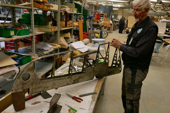
Caudron's horizontal stabilizer is taken apartTiistai 27.8.2019 - Member of Tuesday Club Before the summer break the Tuesday Club team managed to dismantle the fabric covering on the horizontal stabilizer of the Caudron C.59. (CA-59), which was used by the Air Force in the late 1920s. Also a few ribs were unfastened, too. The horizontal stabilizer has been badly bent, and it will have to be dismantled into parts to straighten it. The wooden edge of the stabilizer is in the worst condition and repairing it won’t be easy.
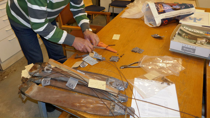
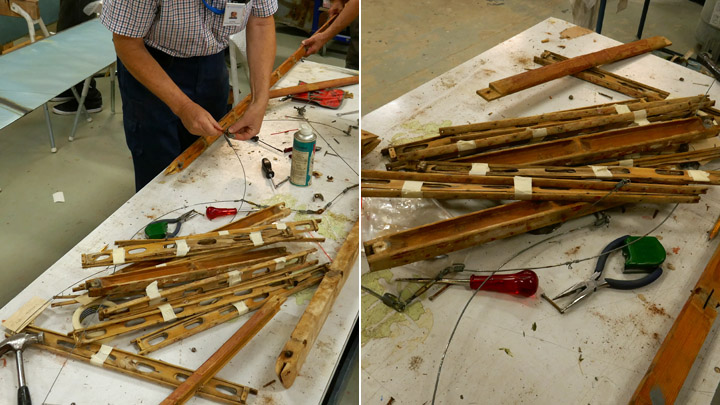
When the Club’s autumn season started on August 13th, the work continued by unfastening the ribs of the horizontal stabilizer. There are 11 ribs, three wooden ones and eight plywood ribs with wooden battens around the edges. The edge battens are in good condition, but the plywood parts are badly rotten. The ribs were numbered before they were unfastened.
There was busy activity around the work table when the team started to unfasten the ribs. It was hard work because the ends of the wooden battens on the upper and lower edges of the ribs had been fastened on the wooden leading and trailing edges with a fishtail joint, secured with screws.
The screws at the ends of the battens couldn’t be unfastened with a screwdriver. The screwdriver had to be used as a lever when pulling the screws out with pliers. When all the battens had been dismantled, they were bundled together with the broken plywood ribs, using painter’s tape. They will have to wait for further activities.
The wooden ribs were dismantled after the plywood ones. The team noticed that no glue had been used when building the Caudron’s horizontal stabilizer. All joints are either fishtail joints or the joints have been secured with bolts, screws or nails.
When the ribs had been dismantled, the fasteners for the stabilizer’s bracing wires on the leading and trailing edges had to be removed. The bracing wires and fasteners and their bolts were bundled together for further activities.
A historical photo from the Finnish Aviation Museum's photo archive shows what kind of aircraft Caudron C.59 is. Other photos: Lassi Karivalo. Translation from Finnish to English: Erja Reinikainen. |
|
Avainsanat: aviation history, restoring, old aircraft, Caudron C.59, CA-50 |
Myrsky activities in JulyTiistai 23.7.2019 - Member of Tuesday Club The Tuesday Club members involved in the restoration work of Myrsky (MY-14) don’t want to stay away from the workshop, not even in July! They want to bring the restoration project forward even during the holiday season.
The team has concentrated on finishing the covering on the starboard wing’s lower side. Now all the inner structures and the equipment inside the wing have been covered with plywood. However, some minor details in the plywood covering are still under work.
When the lower side of the starboard wing is ready, the work will continue on the port wing. The upper side of the port wing has been already covered between the spars. The work on the port wing includes installing all operation mechanisms of the ailerons and landing gear inside the wing, fastening the trailing edge ribs on the rear spars and covering the flap cavity on the trailing edge with plywood. Simultaneously the covering work can be started on the lower side, in the area between the spars, starting at the wing tip. All this work has been done already on the starboard wing, so the team anticipates the work to progress smoothly.
The wing has not been the only Myrsky work item in July. The port and starboard horizontal stablilizers have been covered and the plywood covering seams have been buffed out. The vertical and horizontal stabilizers were fastened on an assembly jig in order to install the root fairings on the seams where the stabilizers meet. The original Myrsky tail root fairings can be used, and no reproduction is needed. However, the original tail root fairings have been slightly damaged, so they need to be straightened and repaired before assembly.
The original duraluminium elevators have also been repaired, because they have some fractures and some parts are missing. The elevators will be installed on the horizontal stabilizer when they have been repaired.
A wooden last was made to shape the Myrsky’s engine cover, ie. NACA ring. In July the last for the upper half of the NACA ring was sent to the company which will prepare the ring. The upper half consists of three aluminium plate segments welded together. The three parts were shaped against the last, using a lead whip. When the shape was correct, the segments were welded together to form the upper half of the NACA ring. The part came back to the Tuesday Club in mid-July. The upper half of the ring will have to be slightly modified and an opening for the engine air intake will have to be made before the upper half can be fastened on the rest of the NACA ring. Photos: Lassi Karivalo. Translation from Finnish to English: Erja Reinikainen. |
|
Avainsanat: aviation history, restoring, old aircraft, VL Myrsky II, MY-14 |
Ilmailumuseot.fi - Aviationmuseums.fi