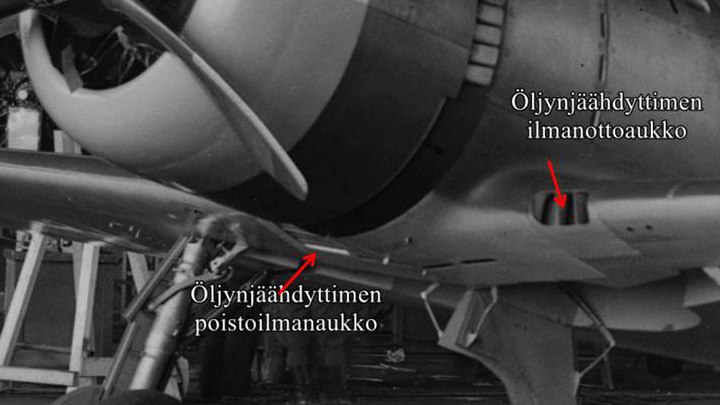
Ducts for Myrsky's oil cooler are builtLauantai 7.9.2019 - Member of Tuesday Club Myrsky’s Pratt & Whitney R-1830 Twin Wasp engine has a barrel-shaped oil cooler, similar to those on the DC-3 Twin Wasp engines. The motor oil is cooled, using air which flows through the cooler. At one end of the cooler there is a horn-shaped duct for supply air and at the other end a horn for exhaust air. Both ducts have a very complicated shape. The cooling supply air intake is at the leading edge of the port wing root. The exhaust air is lead out under the fuselage through an opening in the front fairing at the wing root.
(Öljynjäähdytin = Oil cooler, poistoilma-aukko = exhaust air vent, ilma-aukko = cooling air intake vent). The air flow to the oil cooler is controlled using the three parallel dampers inside the supply air duct. When all dampers are closed, they shut off the air flow to the cooler. By adjusting the dampers, the pilot can control the air flow to the oil cooler and the engine oil temperature.
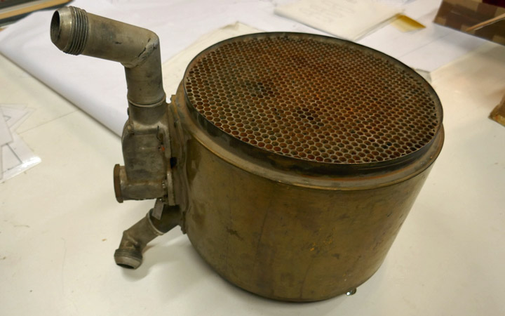
The Tuesday Club team was surprised to find an oil cooler for a Pratt & Whitney R-1830 Twin Wasp engine on the shelf of the working space in the Finnish Aviation Museum. The museum gave the oil cooler to be installed on the MY-14 engine, which was greatly appreciated. When an oil cooler was available, the work on the supply and exhaust air ducts could be started.
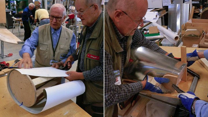
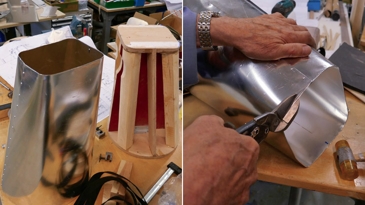
There are no original oil cooler ducts for Myrsky, so all parts will have to be reproduced. The work was started by building a part of the supply air duct which connects to the left end of the cooler. Myrsky’s original drawings were used to make a horn-shaped wooden last. One end of the last is round in diameter, matching the shape of the barrel-shaped oil cooler. The other end of the last is square is shape, matching the shape of the supply air duct’s other end.
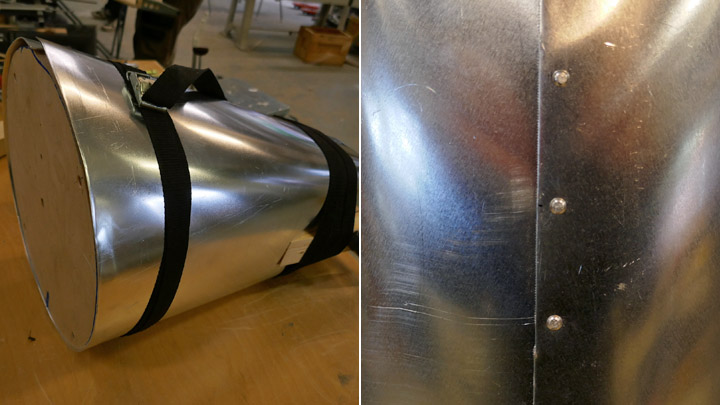
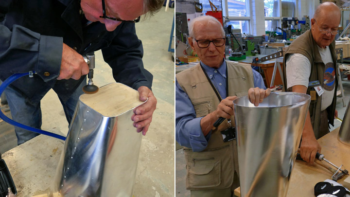
First a sheet of cardboard was wrapped around the wooden last so that a cardboard pattern can be made and used to cut a suitable piece from 1 mm thick aluminum sheet. The appropriate piece of aluminum sheet was cut, and it was bent around the last with tightening straps. The aluminum sheet was bent to match the duct shape. When the semi-finished duct was unfastened from the last, its edges were fastened to each other with rivets. The final phase was to cut the ends of the duct to the right shape, matching the last, and honed smooth. The first part for the supply air duct was ready.
Another similar supply air duct part was made for the display object, which will be built around the fuselage frame of MY-5. A four-meter long test wing is being built during the restoration process and this test wing will be fastened on the MY-5 fuselage frame. The aim of this partly restored MY-5 is to illustrate what the inside of the Myrsky looks like. The fuselage frame will not be covered, and the test wing will be partly covered using transparent plexiglass.
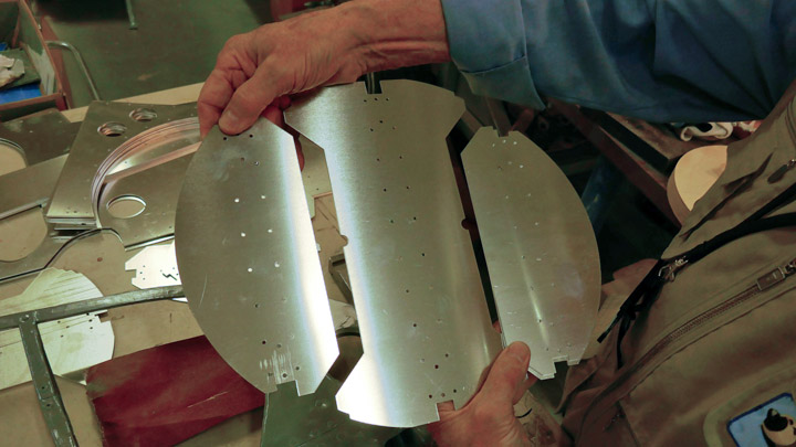
While the supply air ducts for the oil cooler were being made, also the work on the control dampers was started. The leader of the Myrsky-project, Mr. Matti Patteri, programmed the shape of the dampers on a laser cutter, using original drawings. The dampers were laser cut at ProLaser Oy and they have been sent to the Tuesday Club and are waiting for further activities. Photos: Lassi Karivalo except historical photo: The Finnish Avitation Museum's photo archive. Translation from Finnish to English: Erja Reinikainen. |
|
Avainsanat: aviation history, restoring, old aircraft, VL Myrsky II, MY-14 |
Ilmailumuseot.fi - Aviationmuseums.fi