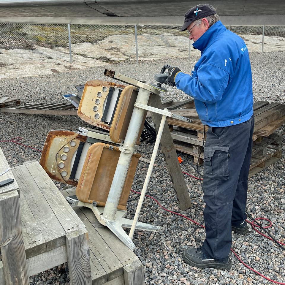
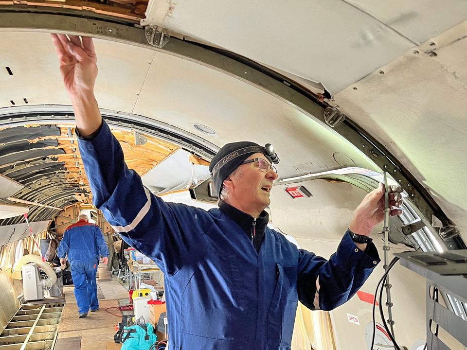
Assembling the Myrsky wing root fairings and the oil coolerMaanantai 15.7.2024 - Tuesday Club member Apart from the Myrsky-project other activities of the Tuesday Club are on hold for the summer break. So the parts of the OH-XEA “Ressu”, Caudron C.59 (CA-50), Valmet Tuuli III (TL-1) and the Link Trainer, heaped in the former Aviation Museum coffee room, can wait for the work to continue halfway through August, when the autumn season 2024 for the Tuesday Club will commence.
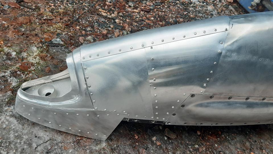
The project members of the Myrsky restoration team at the Tuesday Club have toiled “day in and day out” to finish and assemble the wing root fairings covering the wing/fuselage seam and the oil cooler, with its intake and exhaust air horns. Both these projects have taken more time than planned, so the Myrsky II (MY-14) roll-out, planned for the beginning of August, will be delayed. The summer holiday season both at the Finnish Air Force Museum and at Patria industries have affected in the delay.
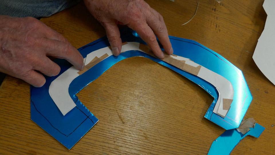
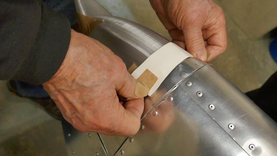
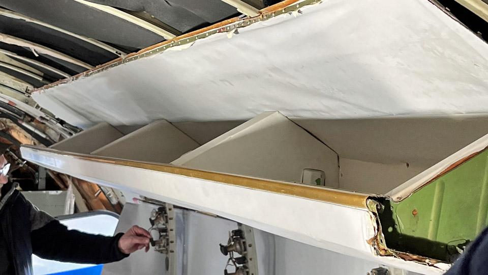
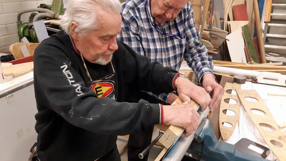
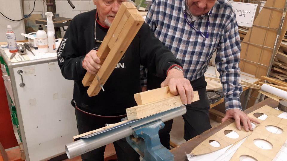
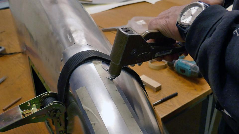
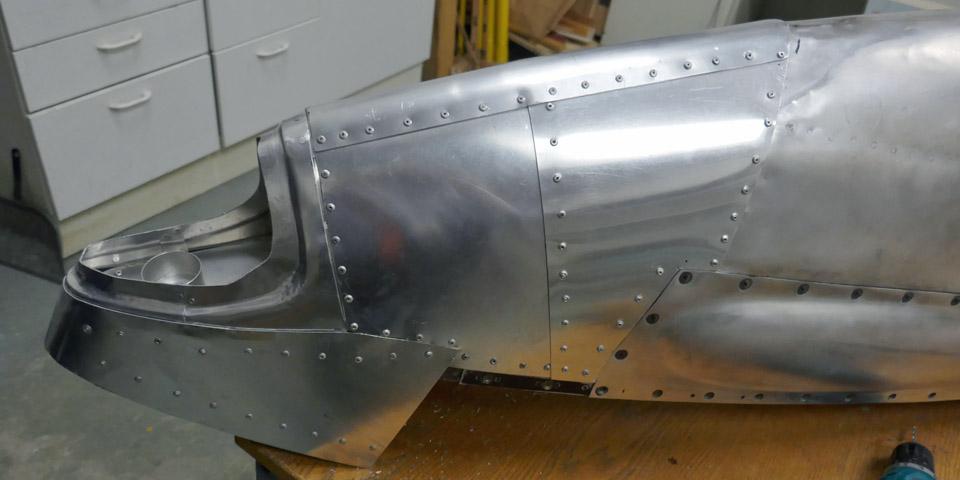
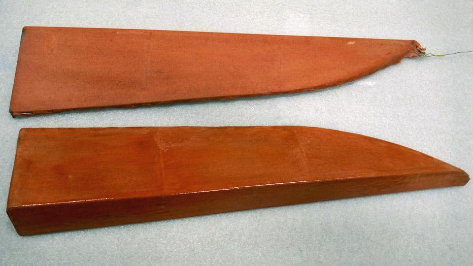
Oval-shaped openings and a flapped hatch were made to the lower surface of both the right and left-hand side wing root fairings. The narrow oval openings are for cooling the wing root fairings, which for their part cool down the engine oil cooler, sheltered by the fairings. The edges of the openings cut to the aluminium plate were strengthened with a 1 mm thick aluminium strip. The strips were fastened with rivets.
The wing root fairing edges were likewise strengthened with aluminium strips on both fairings. That way the fairings stay better in form and are easier to handle when they are more rigid. The strips were riveted to the wing root fairings with countersunk rivets.
Photo by Heikki Kaakinen
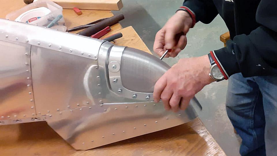
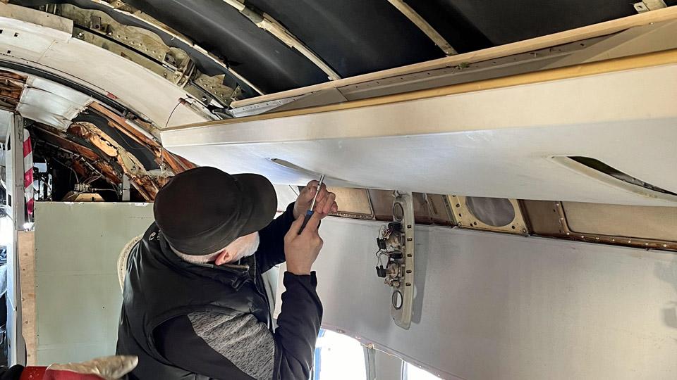
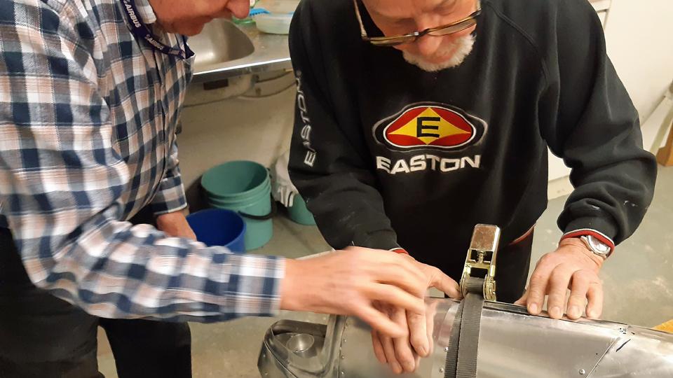
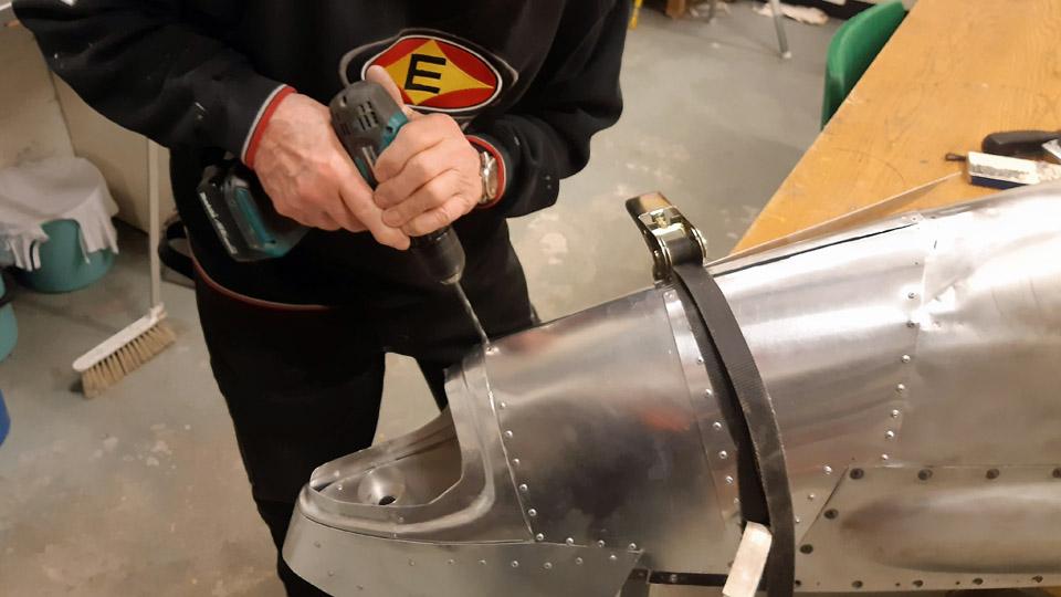
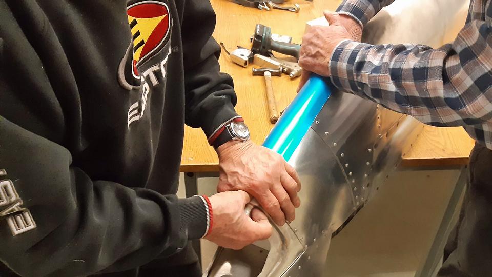
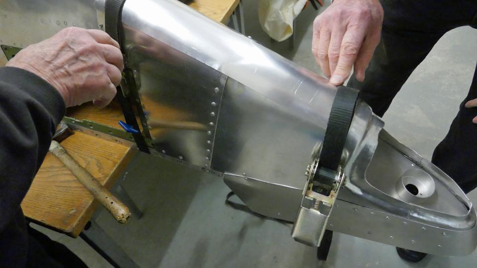
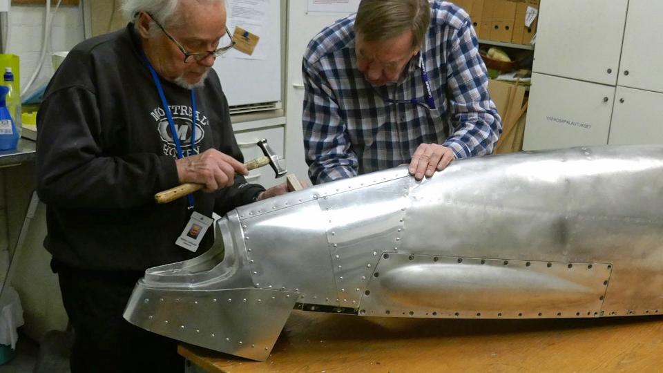
When the openings in the right-hand side wing root fairing were ready, the fairing was fitted in place. After that, the end of the horn for the exhaust air could be pushed into the opening in the fairing and fasten the other end of the horn to the oil cooler. It was noted that the exhaust air horn fitted its opening just like it should.
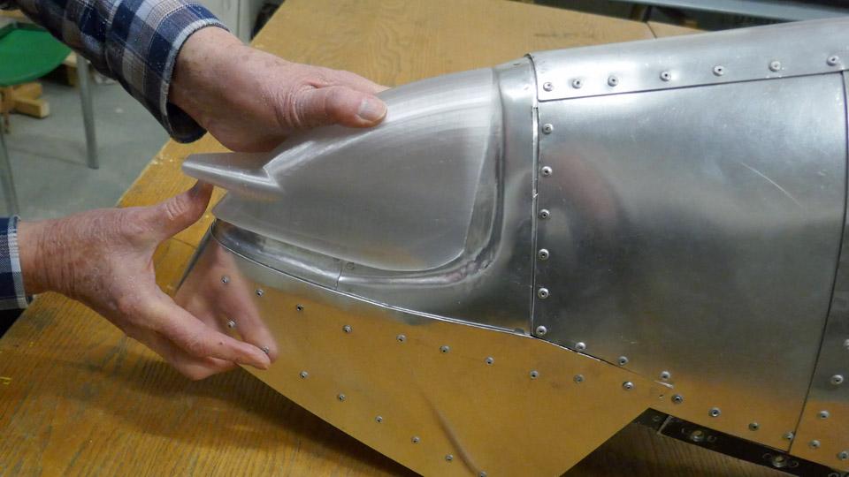
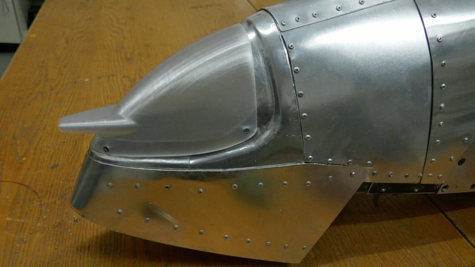
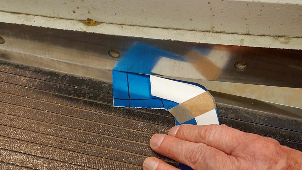
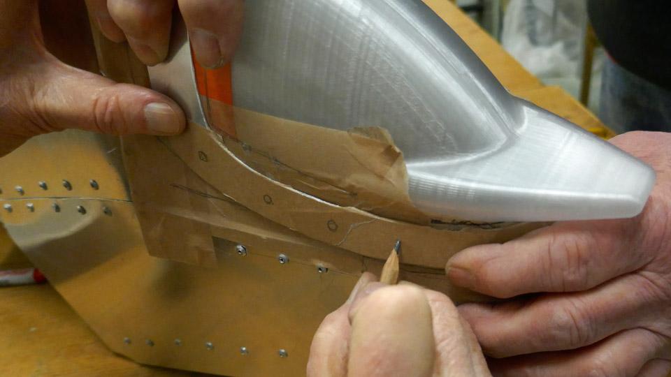
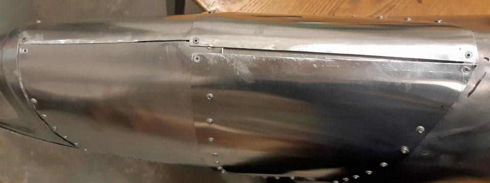
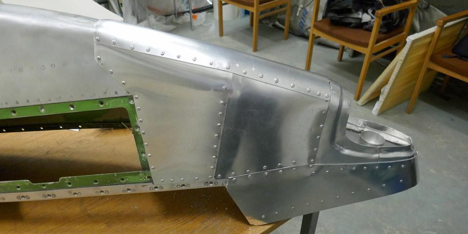
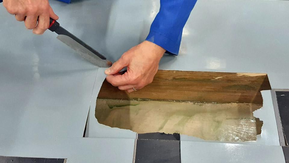
Left hand side photo by photo archive of Finnish Aviation Museum. Next in turn was the making of the cover for the space for the mouthpiece of the intake air horn. The mouthpiece of the horn is situated in the leading edge of the wing in an area limited by two ribs and the front spar. Cooling air for the oil cooler is taken through an opening in the wing’s leading edge. The horn for the oil cooler intake air is for the most part located under the left-hand side wing root fairing, but the mouthpiece of the intake air horn reaches outside the fairing edge.
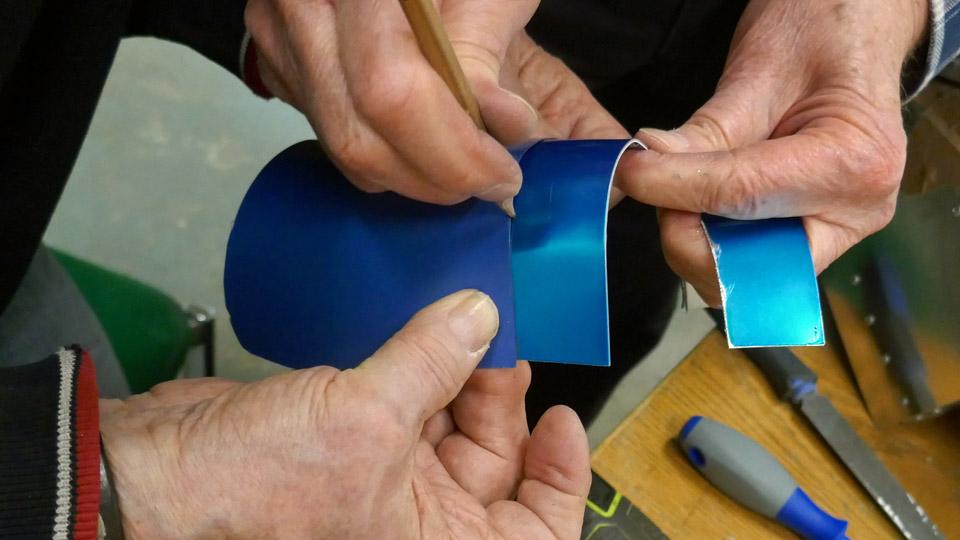
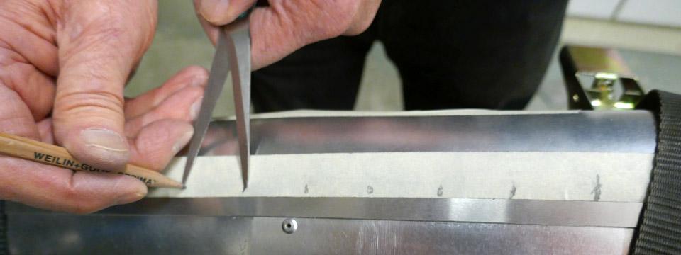
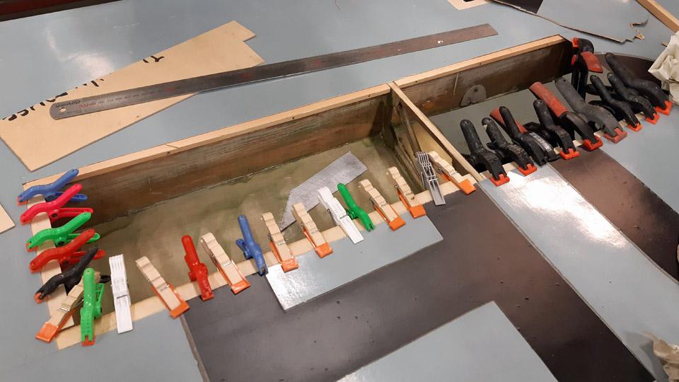
Photos by Heikki Kaakinen. When the intake air horn for the oil cooler and the left-hand side wing root fairing had been installed once again, we checked once more that the air intake horn’s mouthpiece was exactly flush with the wing’s leading edge. Now we could start to make the cover for the space for the mouthpiece of the air intake horn. The space will be covered with a shield made of aluminium sheet, with an opening for the air intake horn. The shield will be fastened to the wing ribs and the edge of the front spar.
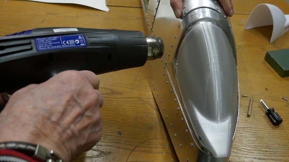
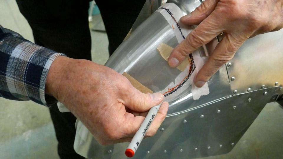
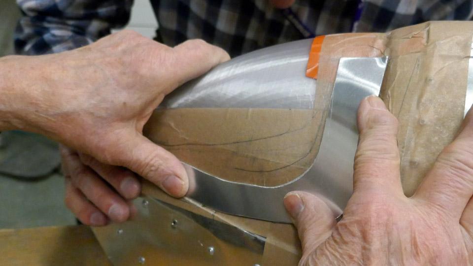
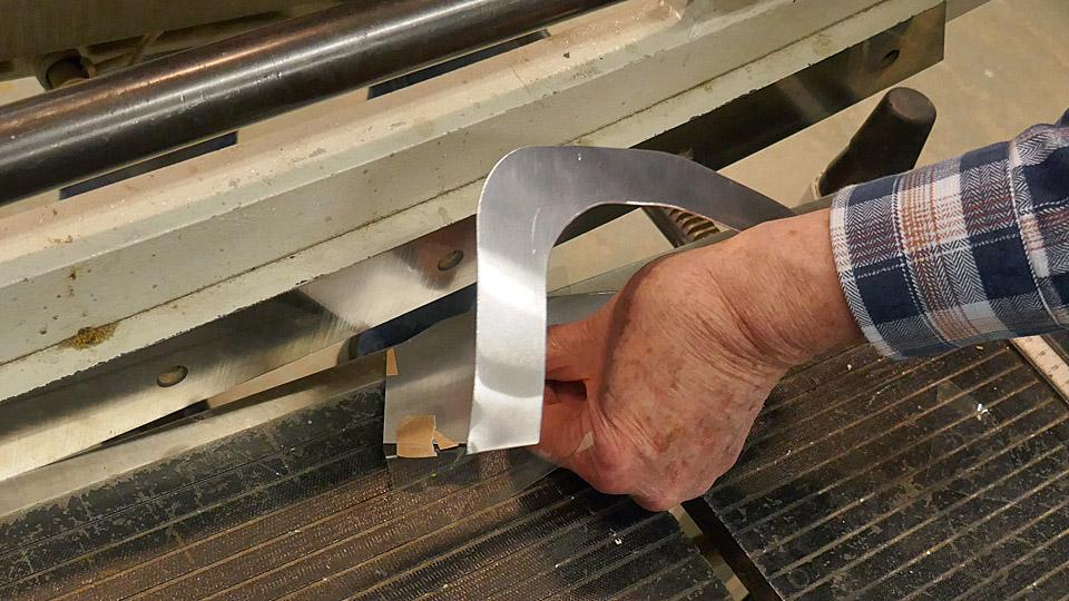
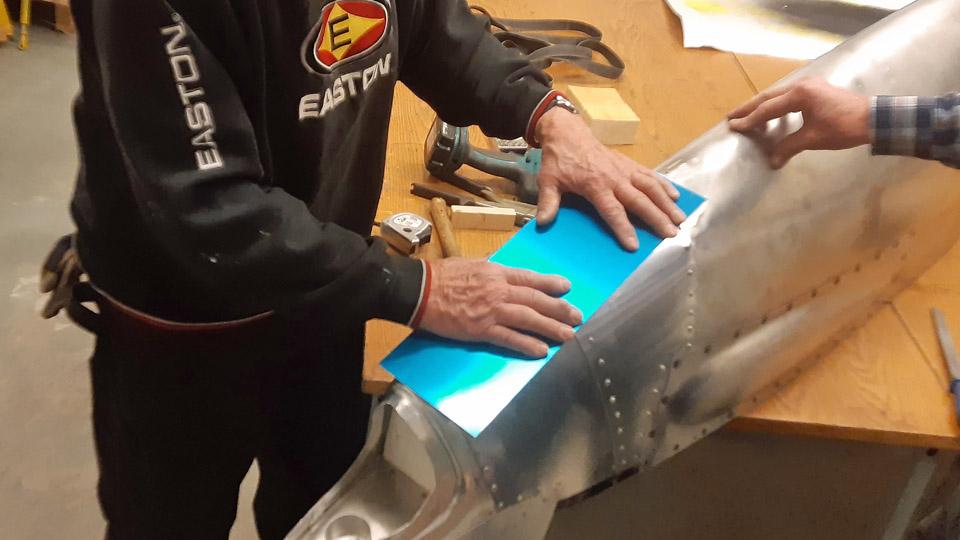
The blank for the shield was cut from 1 mm thick aluminium sheet. The blank was bent to match the leading edge shape. After that an opening for the air intake horn for the oil cooler was made. The half-ready shield was fitted to its place. It was observed to sit well. The edges of the opening of the shield were bent inwards by forcing.
Photo by Jorma Laakkonen.
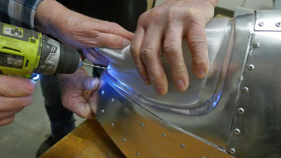
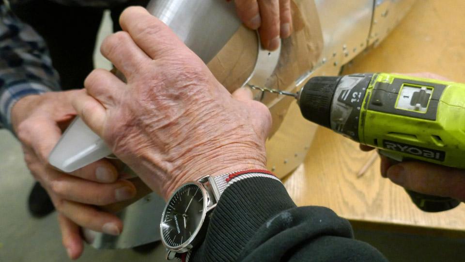
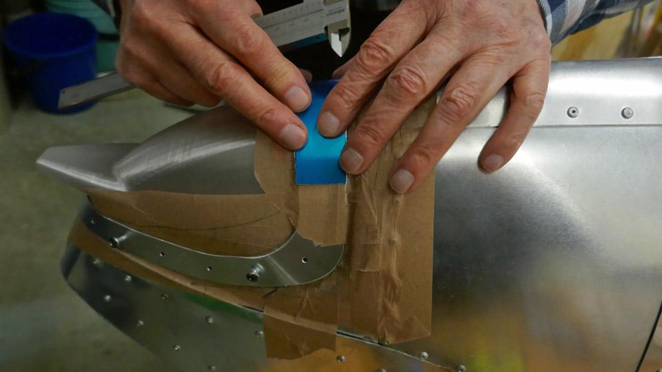
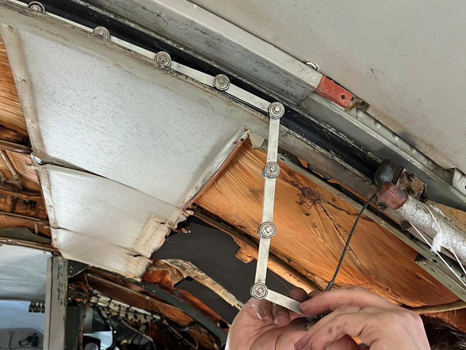
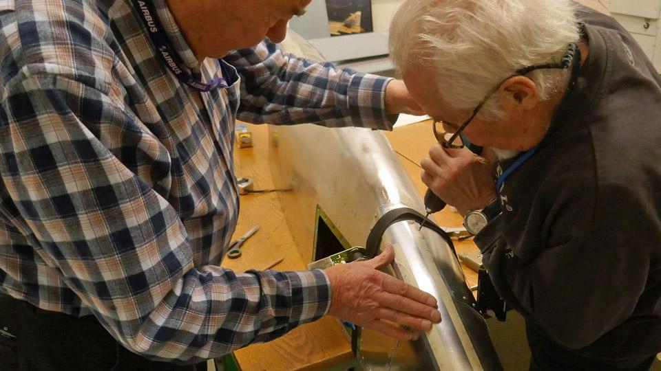
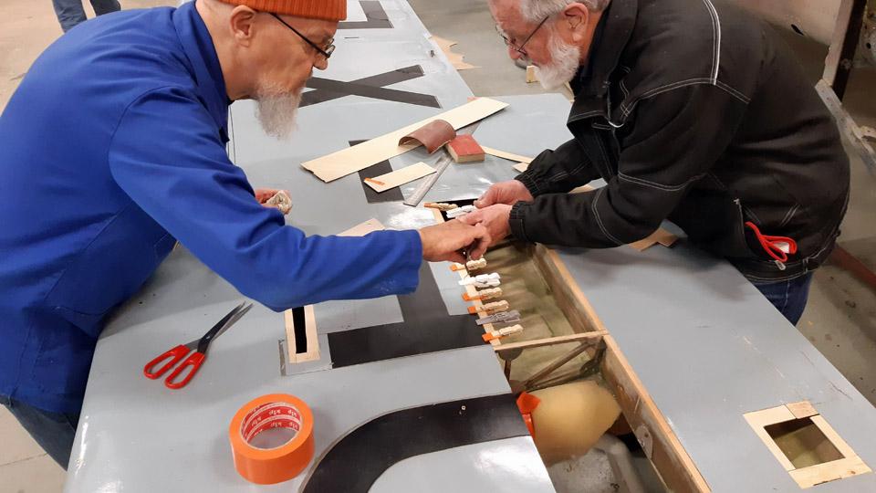
The aluminium shield covering the mouth of the oil cooler intake air horn will be fastened at its edges with screws and flange nuts to the wing ribs and the wing spar. On the fairing side the right-hand edge of the shield remains in between the stem fairing and the metal wing rib, i.e. it will be fastened to its place simultaneously with the edge of wing root fairing. Holes for screws were drilled at the edges of the shield. The holes were strengthened with “crickets” or brass strengthening rings.
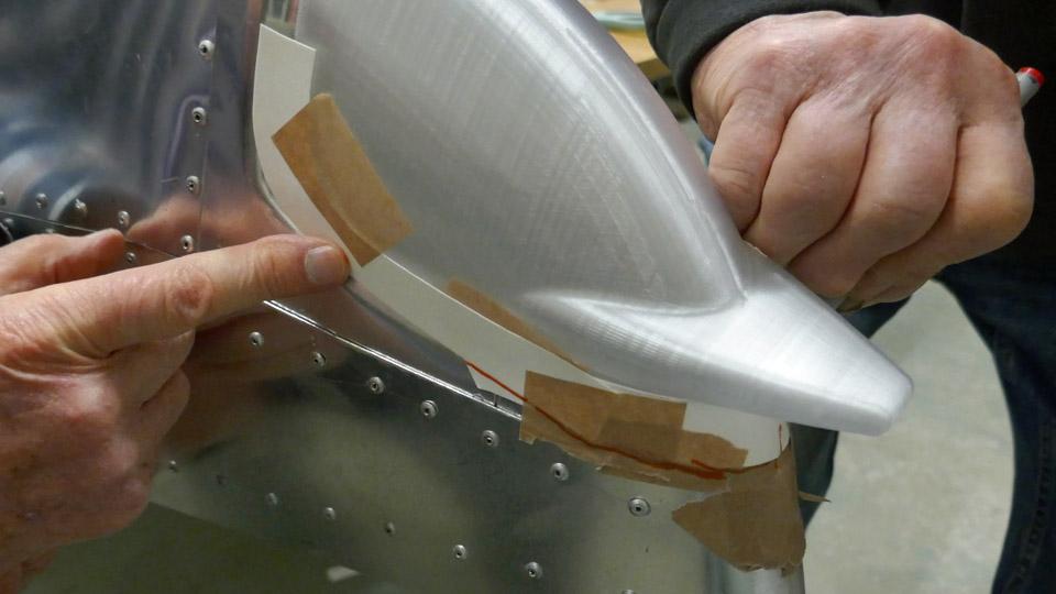
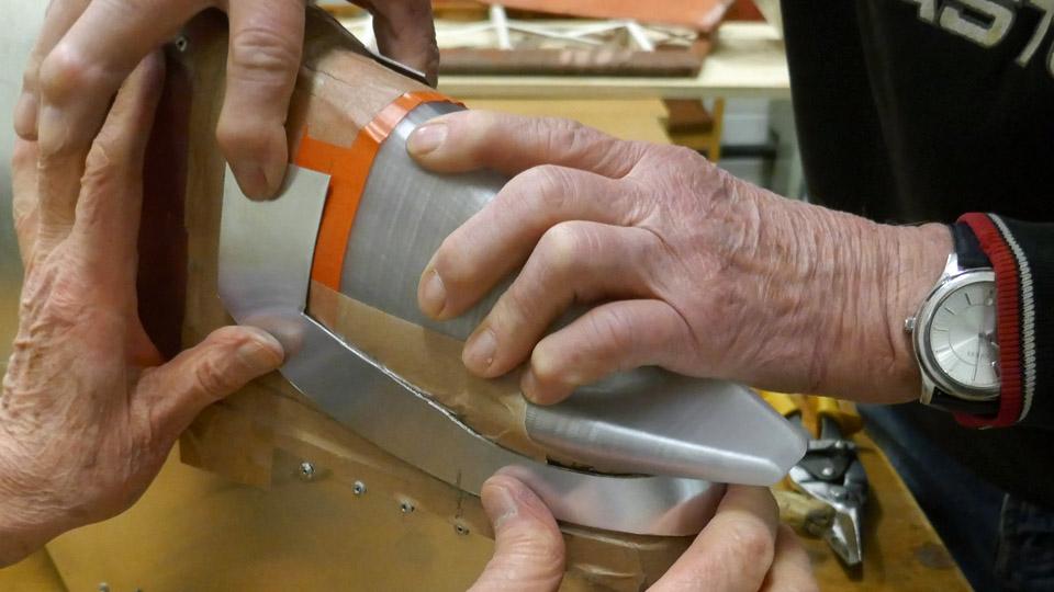
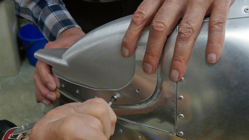
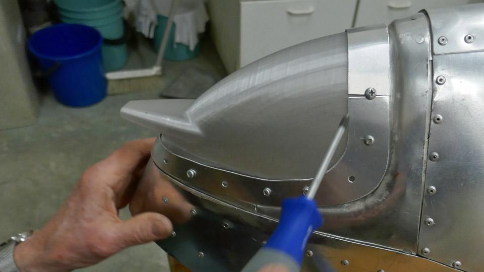
Photo by Heikki Kaakinen. The shield was now ready to be test-fitted together with the left-hand side wing root fairing. So the shield was screwed at its edges with a few screws to the leading edge rib and the front spar’s upper and lower edges. After this the left-hand side wing root fairing, next to the oil cooler, was fitted to place. The outer edge of the fairing curved snugly over the air intake horn’s mouthpiece shield’s edge. Assembling the wing root fairing and the shield needs only some fine adjustment. When the fittings of the oil cooler air intake and exhaust air horns, wing root fairings and the air intake horn mouthpiece shield are ready, the aluminium parts that haven’t been chromated will be taken to Patria Industries for yellow chromating. The chromating will take place at the beginning of August. By now it’s clear that the preplanned roll-out event of the MY-14 Myrsky fighter will be postponed. But, as they say, it’s worth while waiting for something good. Photos by Lassi Karivalo except if otherwise mentioned. Translation by Matti Liuskallio. |
|
Avainsanat: aviation history, restoration, MY-14, VL Myrsky, Tuesday Club |
A busy weekend at Caravelle at Turku airport during July 13th and 14thMaanantai 15.7.2024 - Ismo Matinlauri This weekend was the busiest we have had so far this year at our Caravelle. In this blog you will find some photos from the successful events. Saturday, July 13thOn Saturday there was a display of French vintage car technology beside the Caravelle.
Club Renault de Finlande is celebrating its 40th anniversary this year. They started their Finland Tour from Turku airport on July 13th. For Renault 2024 is a year of celebration as well, the company was established 125 years ago. Below some photos from the sunny Club Renault de Finlande event. The weather conditions were favourable, and the temperature climbed to +26 degrees Centigrade.
There was a nice collection of vintage Renaults on display.
The day was successful also for Caravelle as we had well over 50 visitors. Sunday, July 14thOn Sunday morning it was rainy in Turku and the temperature was much lower than on Saturday, only +18 degrees Centigrade. Despite the drizzle, we celebrated the National Day of France and hoisted the flag appropriately. In the staff room “Café Caravelle” there were naturally fresh croissants available for our volunteers.
There were less visitors than on the previous day, probably due to the weather. However, there were more than a hundred visitors during the weekend, and we can be very satisfied with these summer events. Next week we will have the main effort of the summer as Caravelle will be open to the public during the Tall Ships Race event in Turku. The aircraft is open daily from 10 am to 3 pm from Thursday to Sunday, July 18th – July 21st. If you are in the Turku area next week, come and visit us at the airport! Photos by Ismo Matinlauri Translation by Erja Reinikainen. |
|
Avainsanat: aviation history, restoration, Caravelle, OH-LEA, Sinilintu, Bluebird |
Caravelle's holiday seasonLauantai 6.7.2024 - Ismo Matinlauri The Caravelle Turku team volunteers finished their spring season at the end of June. The team members started their well-earned holiday at their cottages, travelling or being active in other hobbies. In the beginning of August they will return to Caravelle restoration work. During the spring season the Turku team and the assisting technical team totalled almost 850 hours of voluntary work. Some news about the most recent work in June are shown below. Furthermore, the polishing of the lower part of the aircraft’s fuselage was continued whenever weather permitted. The officeRamirent Oy (the equipment rental company) donated us two modular containers which were joined and assembled beside the Caravelle. Now we have a combined office and shop on site.
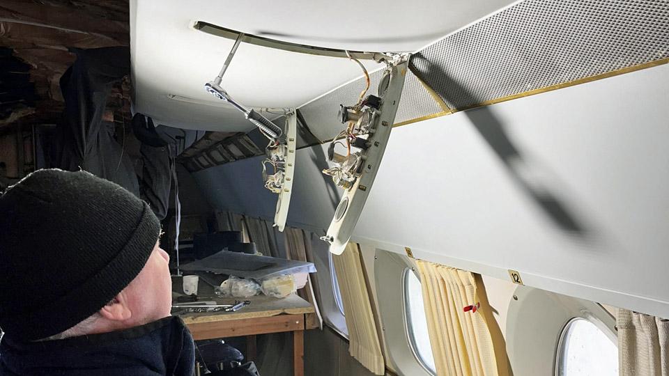
A power supply was installed, and the office was furnished. Everything is ready inside and outside and we can use our new space during the summer season. A housewarming event will be arranged in August. Also our unofficial “Café Caravelle” (i.e. the Turku voluteers’ coffee break facility) was moved from the aircraft cabin into the new office. Now there is more space for the future interior work, and it is also easier to move in the cabin as there is less material and furniture. The passenger door and cabin partitionsThe left-hand side passenger door’s complicated opening and counterbalancing mechanism was repaired during the spring. This was quite an effort and a series of four blogs was written about it earlier. The repaired door mechanism works fine, and the passenger door is open during the visiting hours.
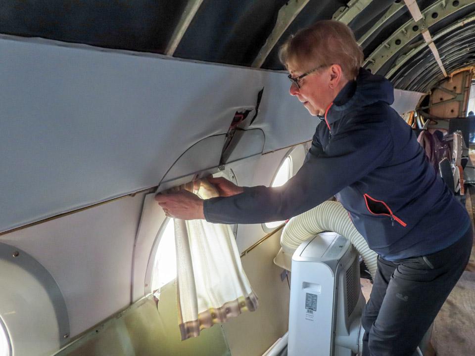
The partitions in the front part of the cabin are fitted into place in the two photos. The passenger door is open to confirm the correct location of the partitions so that the door opening mechanism is not disturbed. The partitions will be resurfaced in August, using material which resembles the original one, and then assembled into place. Electrical installationsThe electrical installation work is almost completed. Power outlets are already in place and connected. The wiring for lighting is almost ready, too. In August when the work continues, LED lighting will be installed on the flight deck and in the toilets and galley area in the rear section.
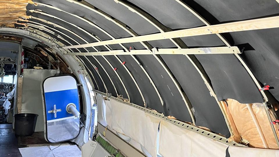
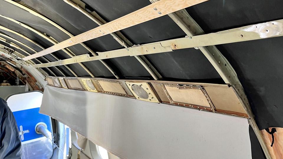
A LED-strip will be installed in line with the upper edge of the cabin overhead hat rack. The photo shows its wiring, waiting for the ceiling surface material installation. After that the LED-strip mounting can be assembled.
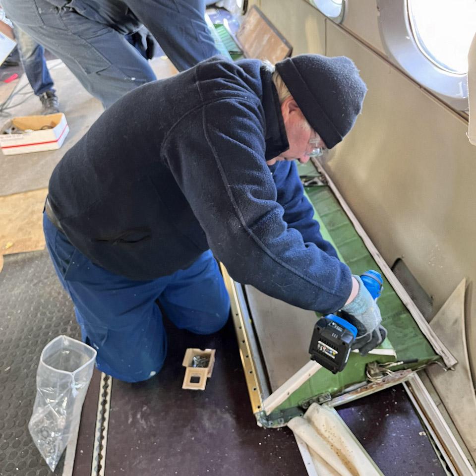
The last photo shows the white main distribution board which will be installed into the former equipment rack behind the flight deck, on the left-hand side. Wiring from the distribution board is located under the cabin floor. The wiring was being installed when the photo was taken. Before going on holiday we collected all tools and tidied up inside the aircraft for the visitors’ events. The Caravelle will be open to the public on several occasions in July. Our volunteers will be on site to introduce the aircraft and its history. Photos by Ismo Matinlauri. Translation by Erja Reinikainen. |
|
Avainsanat: aviation history, restoration, Caravelle, OH-LEA, Sinilintu, Bluebird |
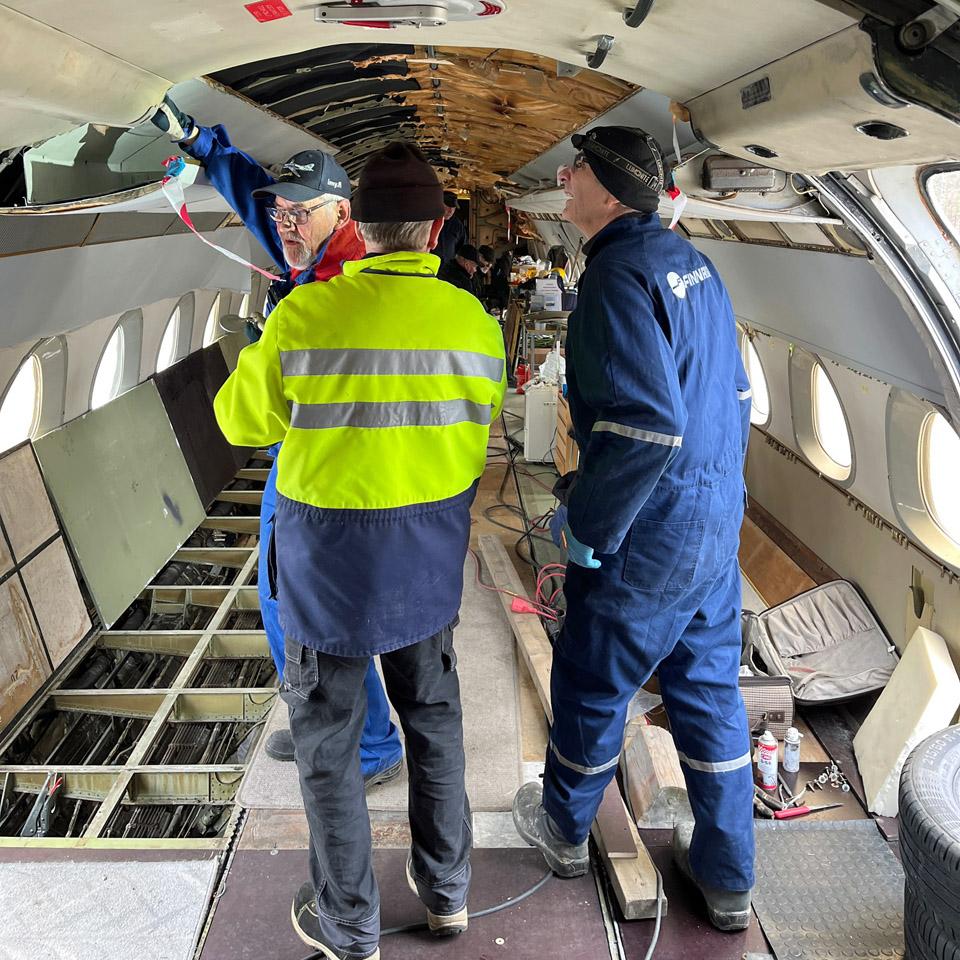
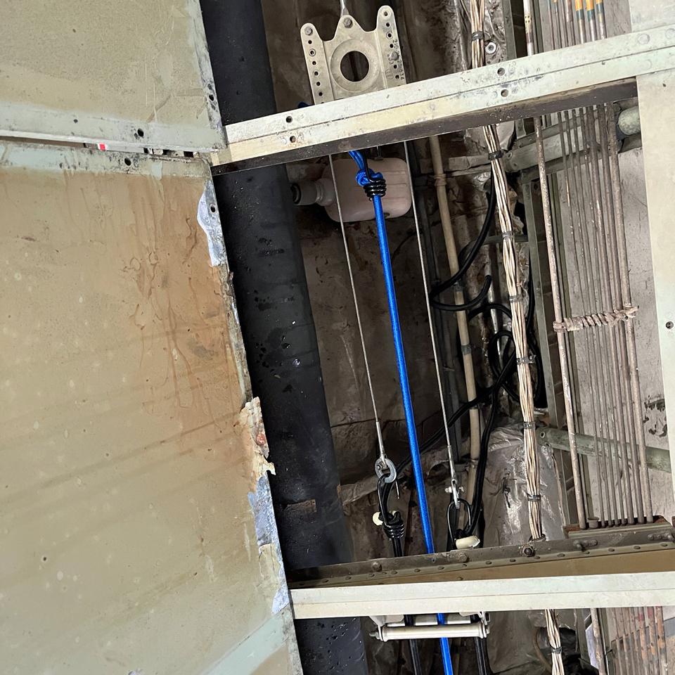
Caravelle's passenger door mechanism is repaired - Part 4Maanantai 27.5.2024 - Erja Reinikainen ja Martti Saarinen The reparation procedure of the left-hand side passenger door’s complicated opening and counterbalancing system has been described in the previous blogs and the story is completed in this one. During our previous reparation visit the door was already functioning in the desired way but after a long working day the last adjustments and final inspection were not done. Therefore the door could not be taken into use yet. In the week before our latest visit to Turku we asked the Turku team to check whether the bungee ropes are still tight when the door is closed. The reply was reassuring, they are tight all right. This meant that nothing had failed or broken while the counterbalancing system had been carrying a full load for a week while the door remained closed. After arriving we lifted the cabin floorboards and checked the bungee ropes in the side tunnel under the floor. The ropes were still tight, so everything was ok. The polishing team was working outside, polishing the lower section of the passenger door and we had to wait for a while before we could open the door. It could be opened without problems.
Photo by Ismo Matinlauri. When the door was open and in its highest position, we could see that the bungee ropes had slackened a little. This we had expected to happen. There is a convenient adjustment at the far end of the each bungee cord attachment cable: the fastener pin is moved on the connecting piece into the hole where the desired tightness of the bungee rope is achieved. The adjustment was done in a couple of minutes and the door operation was tested again. Everything worked fine. After this the last installations were done, and the final inspection was completed.
The Turku team members were given user training on how to operate the door. Now it can be used safely and there is no need to go back and forth through the small and low service door. The passenger door was open for the visitors during the weekend opening hours on May 25th – 26th.
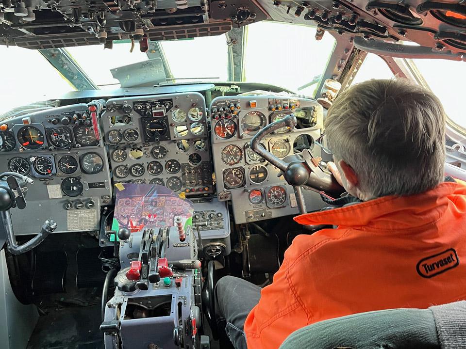
Meanwhile, work on the flight deck was continued to have the side windows replaced. The small triangular windows had already been replaced and now the large rear windows were under work. The windows are the emergency exits for the flight deck crew, so they are easy to remove by opening the locking levers and lifting the window away.
However, this was easier said than done after the aircraft had been standing outside for almost fifty years. A lot of gun oil and some patience were needed to open the locking mechanisms but eventually they could be opened. Installing the new window on the left-hand side went smoothly but the right-hand side was more difficult. Some machining was needed and two assistants helping before the window was in its place. Photos by Martti Saarinen except if otherwise mentioned. Translation by Erja Reinikainen. |
|
Avainsanat: aviation history, restoration, Caravelle, OH-LEA, Sinilintu, Bluebird |
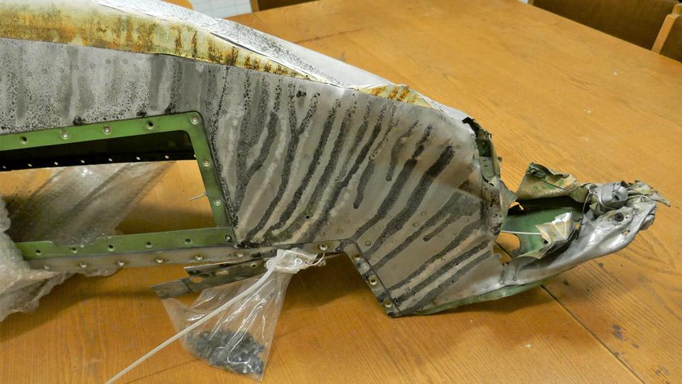
The right-hand side wingtip of Caravelle III "Bluebird" is delivered to TurkuSunnuntai 26.5.2024 - Tuesday Club member The Caravelle III "Bluebird" (OH-LEA), on display in Turku, has until now been without the wing tip piece of its right-hand side wing. For about a year, the wingtip has been under repair and parts of it have been rebuilt at the Tuesday Club, working at Finnish Aviation Museum. The leading edge of the wingtip had been destroyed while the Caravelle, in SAS colours at the time and carrying registration SE-DAF, stood by the edge of Arlanda airport for decades. Probably some airport vehicle had bumped into the aircraft.
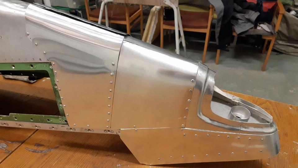
The repair work of the right-hand wingtip section was completed at the Tuesday Club, but it wasn’t taken to Turku until now. The wingtip was transported from Finnish Aviation Museum in Vantaa to Turku airport, to be assembled on “Bluebird’s” wing. The wingtip section is too large to be transported in an ordinary passenger car. It was packed properly and loaded on the Aviation Museum yard on a trailer. The journey towards Turku could begin.
The vehicle was welcomed at Turku airport by the Caravelle Turku restoration team. The team unloaded the wingtip from the trailer and carried it under Caravelle’s right-hand side wing to wait for assembly.
Right-hand photo by Reijo Siirtola.
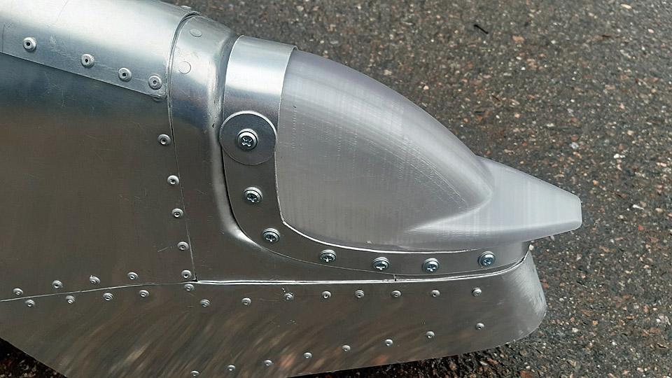
Now all Caravelle work allocated to the Tuesday Club have been completed. The work included repairing the nose bulkhead edge and the damaged radome, refurbishing and painting the wall panels of the flight deck and the corridor leading to the flight deck, repairing the glare shield above the flight deck instrument panel, building the frame for the navigation light on the right-hand wingtip and preparing the navigation light globes by 3D-printing.
Photo by Ismo Matinlauri. Furthermore, in 2022 we built stands for supporting the Caravelle’s fuselage and wings during the transportation from Arlanda to the former shipyard hall in the Pansio harbour area in Turku. We also restored the Caravelle III towbar, brought from Arlanda, which was in poor condition. The towbar is already in place, fastened on “Bluebird’s” nose wheel. Photos by Lassi Karivalo except if otherwise mentioned. Translation by Erja Reinikainen. |
|
Avainsanat: aviation history, restoration, Caravelle, OH-LEA, Sinilintu, Bluebird, Tuesday Club |
Caravelle's passenger door mechanism is repaired - Part 3Tiistai 14.5.2024 - Erja Reinikainen ja Martti Saarinen The reparation procedure of the left-hand side passenger door’s complicated opening and counterbalancing system has been described in the previous blogs and the story continues in During the previous reparation effort the door could be opened with a manual winch, but the bungee ropes which were tested, were too weak to be used for opening and counterbalancing the door. There were also problems with the new roller chain and the door seemed to be slightly tilted. The technical team thought the problems might be caused by wrong adjustment of the cables or bungee ropes, or due to some part being bent in the process. Stronger bungee ropes were ordered from the US, and when they arrived it was time to try again to make the door work.
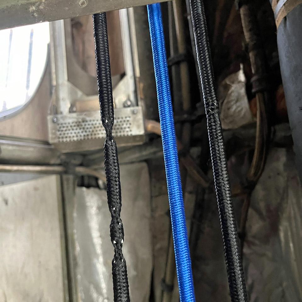
The attachment pieces at the door end of the new roller chain had been modified a little and this seemed to help to correct the door position. It now moved down without tilting on one side. Terminals made of copper tube had been prepared for the two new bungee ropes in the lifting mechanism, to fasten the bungee ropes to the sliding carriage and to the door lifting cables. For establishing the correct length of the bungee ropes, temporary fasteners were prepared for the rear end of the ropes to fasten them to the end cable of the bungee track. In the first phase the blue bungee rope in the middle was not changed, it remained as it had been in the previous testing.
The day was spent adjusting the length of the bungee ropes and cables, testing the door movement every now and then, and adjusting some detail once again. Some changes were also made on the bungee rope track. Eventually the door could be opened smoothly and rather lightly but closing it fully from its down position still required a fair bit of force. At this point terminals from copper tube were made also for the rear end of the two outer bungee ropes and the temporary fasteners were removed. The third bungee rope in the middle was replaced with a sturdier one and terminals were made for its ends. With this arrangement the door could be moved with less force but closing it fully was still difficult. After some additional adjustments the door was functioning as it should, but it was not taken into operation yet. The technical team had been working for full eight hours at this point, so it was time to call it a day. Next time the installation will be completed, and the adjustments will be checked after the bungee ropes have been under tension for a longer period when the door has been shut.
During the day there were naturally also other activities going on: The assembly of the office and visitor centre (which is a prefabricated reusable and movable small building) was continued and the space was prepared for the opening hours on the coming weekend. Tables and sales items were moved from the aircraft into the new building. The broken sealing strip on the passenger door was replaced with a new one.
On the flight deck there was a time-consuming battle to open the emergency exit windows’ locking mechanism which had rusted solid. Among the material brought from Arlanda in 2022 there are two windows for both sides of the flight deck. They are in better condition than the existing ones and they will used to replace the old ones. Eventually the rust on the mechanism began to yield and the locking of the windows can be opened.
The planning of the new padding for the passenger seats was continued. A workable solution is beginning to take shape. Photos by Erja Reinikainen. |
|
Avainsanat: aviation history, restoration, Caravelle, OH-LEA, Sinilintu, Bluebird |
Caudron C.59 advanced trainer; covering of the horizontal stabilizerTiistai 14.5.2024 - Tuesday Club member Caudron C.59 was an advanced trainer used by the Finnish Air Force in the 1920s. The restoration of the individual aircraft CA-50 was commenced at the Tuesday Club in 2019. The work has advanced in stages. After the Finnish Aviation Museum acquired from abroad cotton fabric designated to covering aircraft, we could start covering the horizontal stabilizer of the Caudron, which had been waiting for some time. We had earlier refurbished the Caudron’s horizontal stabilizer, which had been in very poor condition, by taking it apart and reassembling it for covering.
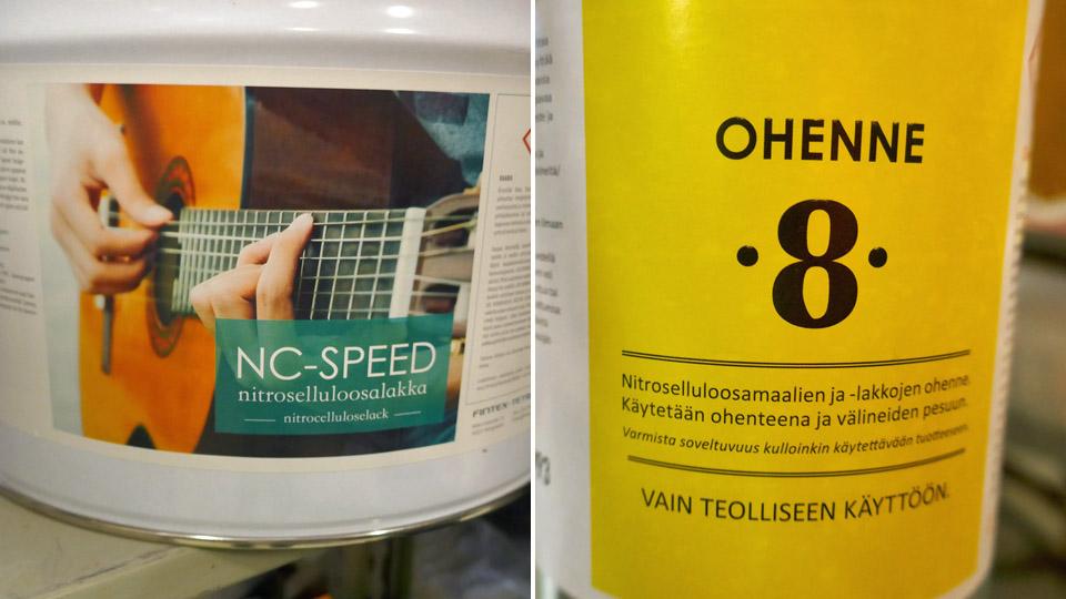
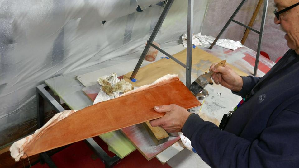
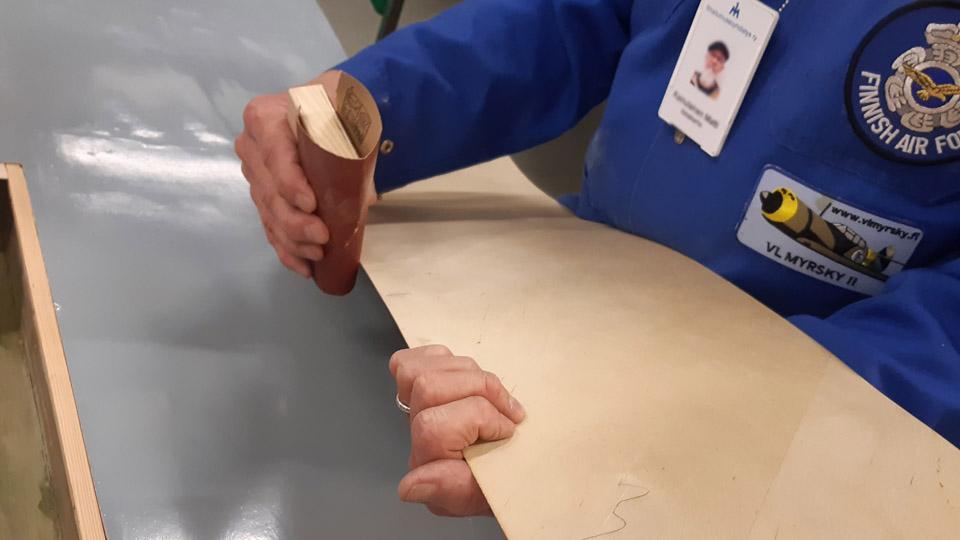
Prior to the covering, it was decided to lacquer with nitro cellulose lacquer the fabric strip covering, wound around the leading edge of the stabilizer. It was made of 50 mm wide linen band according to the original. By lacquering the band covering, the gluing of the covering fabric will be enhanced on the surface of the leading edge of the stabilizer.
Photo by Jukka Köresaar.
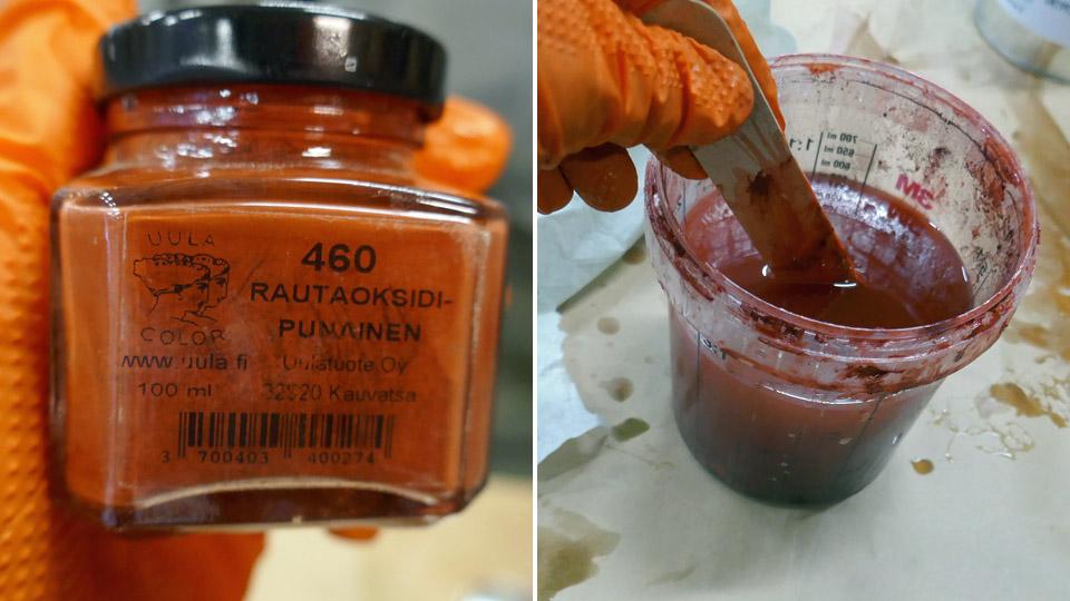
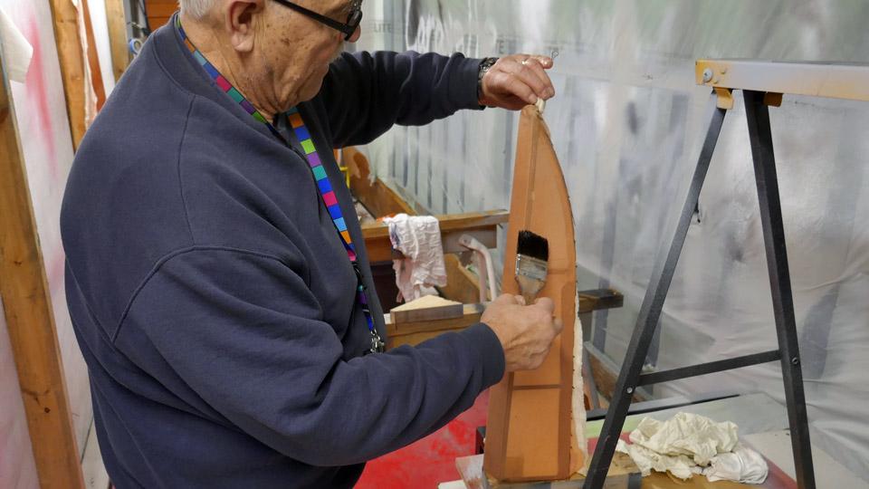
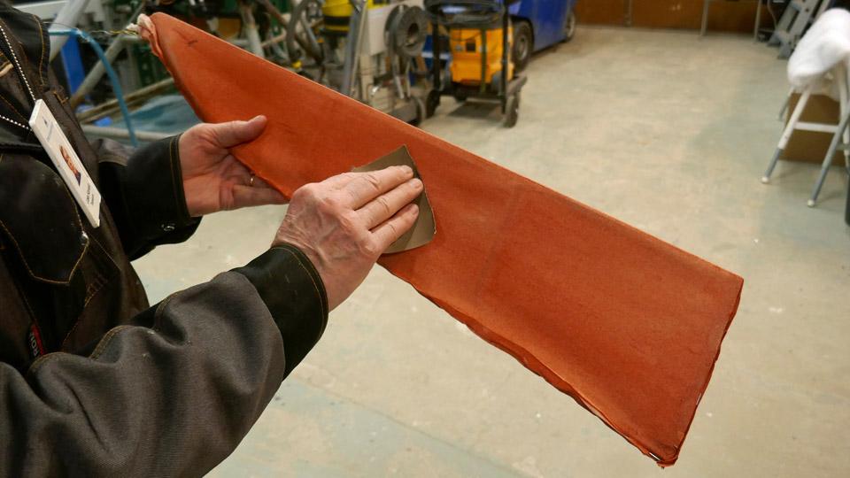
The linen band covering wound on the leading edge of the horizontal stabilizer was lacquered with 75% nitrocellulose lacquer. As lacquer we used NC Speed nitrocellulose lacquer, and it was tinted red with iron oxide powder. After the lacquer had dried, the edges of the linen band had, as we expected, risen as well as the fabric fuzz. So the band covering was sanded smooth, and another layer of lacquer was applied. Even after the re-lacquering, the leading edge band was uneven and the band had to be sanded once more, after which it was lacquered with 100% nitrocellulose lacquer. So the linen band wound around the leading edge had been smoothed, and we could start covering the horizontal stabilizer.
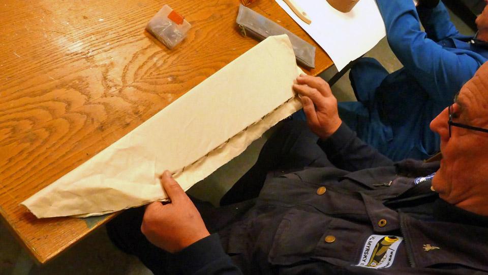
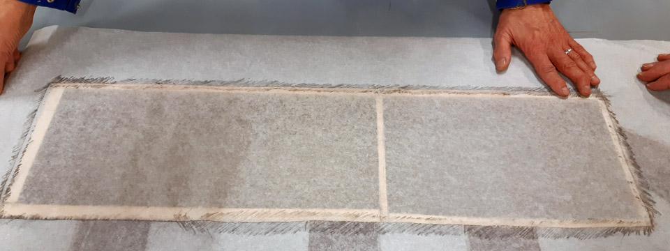
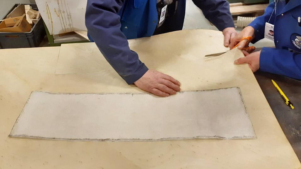
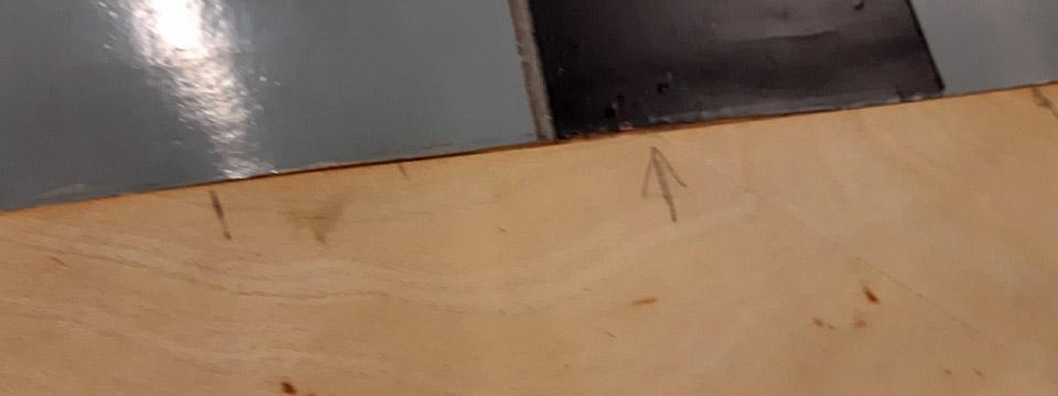
The width of the horizontal stabilizer is 60 cm and its length 120 cm, so a 130 cm wide piece was cut from the 140 cm wide cotton fabric. This way the fabric has enough working allowance to work both in length and width way. The fabric was wound around the stabilizer, which was laid the table, so that the lapels of the fabric reached past the horizontal stabilizer’s trailing edge. We meant to make a bag out of the fabric, which would be open at the trailing edge.
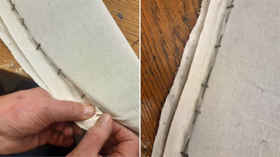
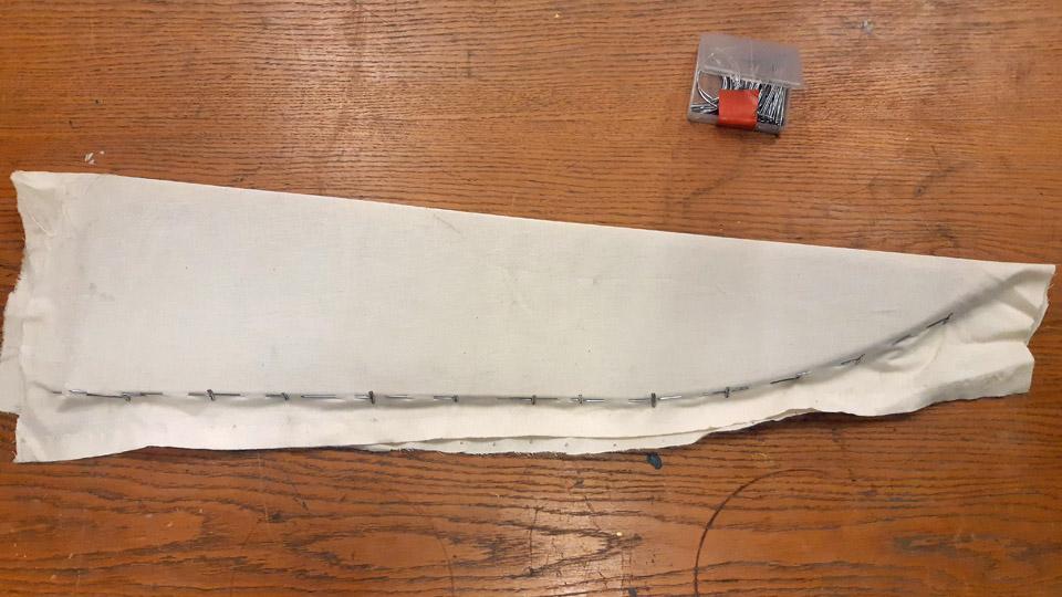
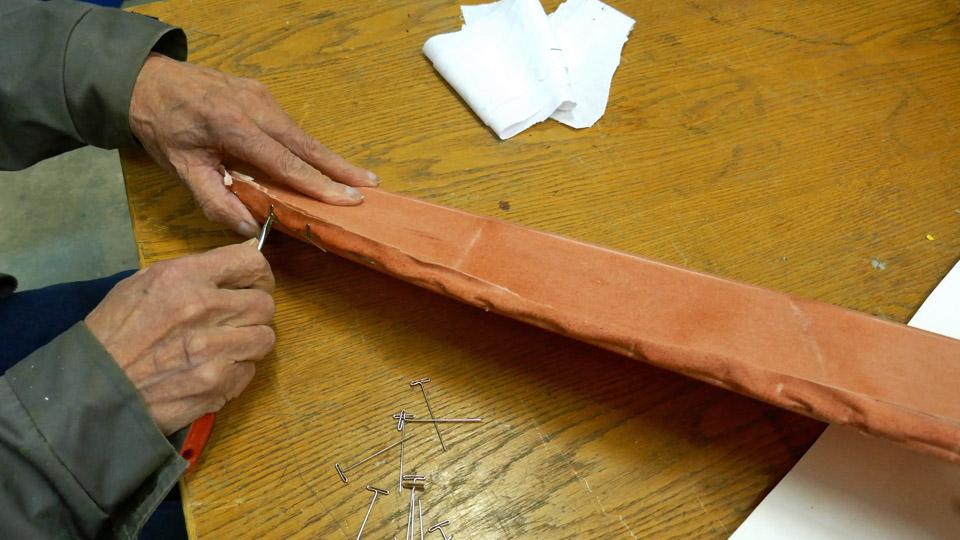
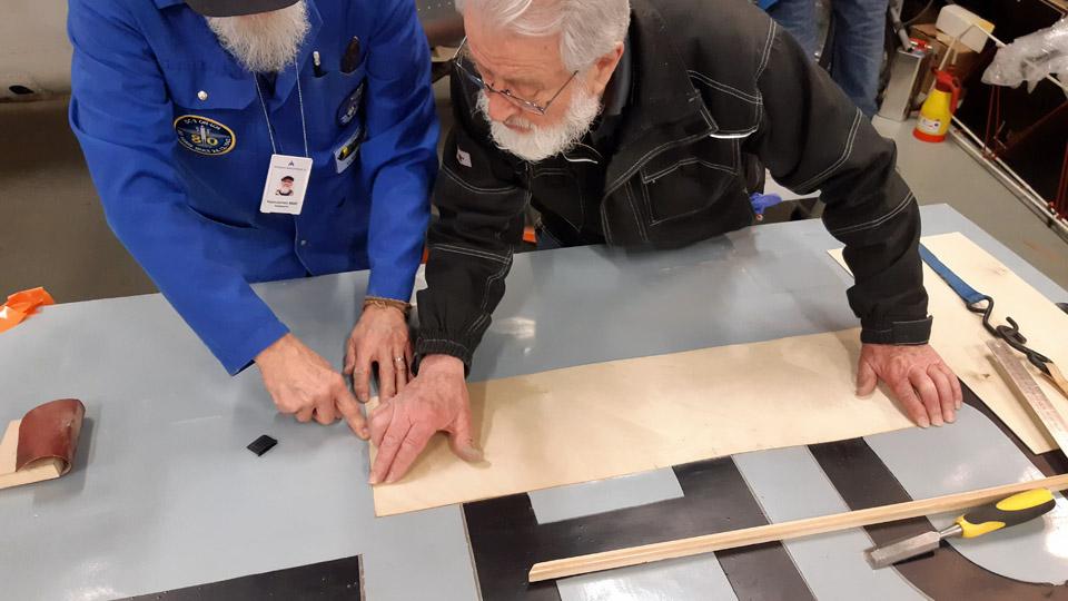
To achieve this, at both ends of the stabilizer the lapels were joined with pins. The lapels were then sewn together with a sewing machine, along the line of the pins. So the fabric was formed to be a bag, open at the trailing edge. When the ends had been sewn, the fabric was turned inside out, leaving the sewing seams of the lapels inside the fabric bag.
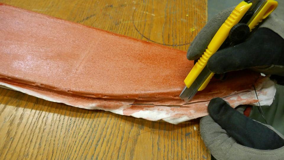
The fabric bag, open at the trailing edge, was drawn on the horizonal stabilizer. The sewing of the fabric was very successful, because the fabric bag had become tight, or rather “skin-tight” on the horizontal stabilizer. Now it was time to sew together the still open trailing edge fabric lapels. For the sewing extra parts of the lapels were cut off, so that the lapels met at the outer edge of the trailing edge batten.
To keep the lapels of the fabric in place when they were sewn together, the fabric was fastened with staples from a stapler at the side of the trailing edge batten. The lapels of the fabric were sewn together with a thin double yarn cotton thread. As a needle we used a curved needle, which was handy for this kind of sewing.
Photo by Antti Laukkanen. The sewing of the covering fabric lapels was done so that the seam formed a continuous serrated shape. When the lapels had been sewn, the covering fabric formed a closed bag over the horizontal stabilizer.
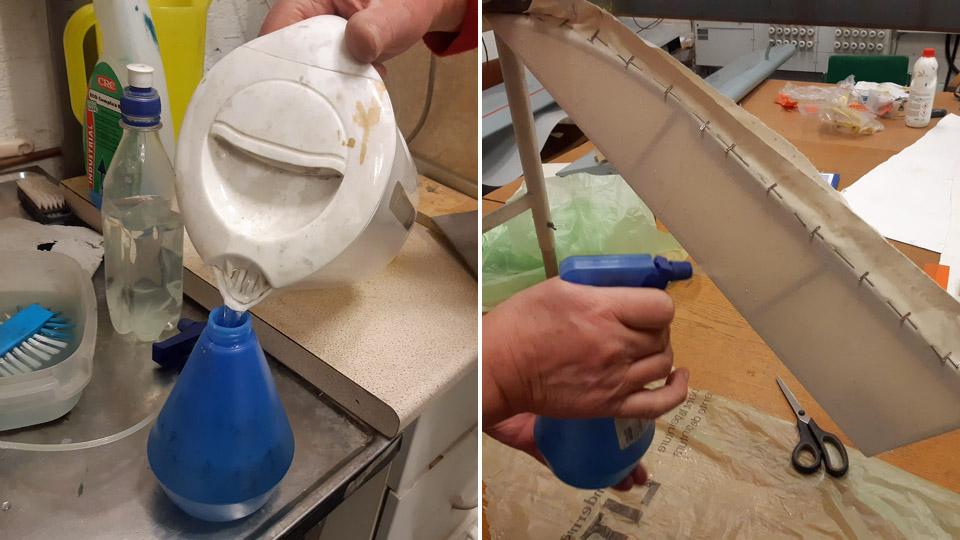
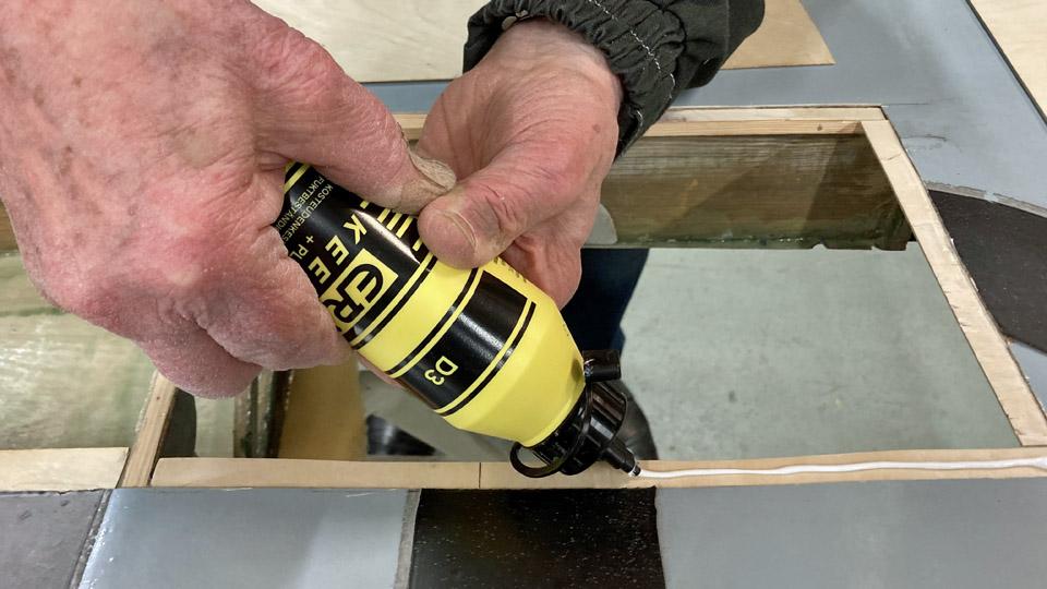
Photo by Antti Laukkanen. The next phase in the work was the water-tightening of the fabric. The stabilizer covering fabric was soaked with boiled, but cooled water, and was left to dry. With water-tightening, the fabric is pre-tightened, because when dried the covering fabric has already tightened a few percent on the stabilizer.
Photo by Antti Laukkanen. The proper tightening of the covering fabric to resemble a drum head, will be made with nitrocellulose lacquer. Before tightening the covering the fabric needs to be sewn on the stabilizer ribs. The sewing will be done by following the original 1920s Caudron stabilizer sewing method. This way of sewing was documented, when the decayed covering fabric was stripped off the Caudron’s stabilizer. According to that, the covering fabric was sewn onto the fabric strips, which were fastened to the stabilizer ribs, with tacking interval of about 3 cm. The fabric strip was for its part tied to the rib’s surface with an edging ribbon. We had done similarly, when refurbishing the stabilizer.
The places of the stitches were marked at each rib on the surface of the covering fabric, using a thin template made of plywood. The stitching places of the sewing needle were marked on the fabric surface with a thin felt pen, through the template holes. Using a curved needle and double yarn thin sewing thread, the covering fabric was sewn stitch by stitch to the edging ribbons that ran along the ribs. A regular space between the stitches made it possible that the needle occasionally pierced the edging ribbon which tied the fabric strip to the rib. When the sewing had been done, the staples could be removed from the fabric surface.
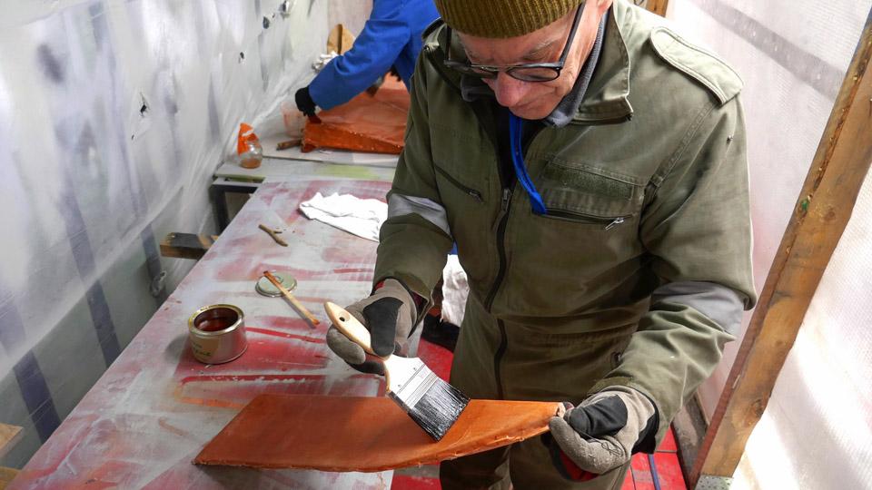
The covering fabric was now sewn to the horizontal stabilizers’ ribs, both on the upper and the bottom surface, so it’s time to move on the next phase of the covering. There the horizontal stabilizer’s covering fabric will be tightened to drum head tightness with nitrocellulose lacquer. As lacquer we use NC Speed nitro cellulose lacquer. Applying the lacquer is started with 25 % thinned lacquer, and from there in stages to the full 100% nitrocellulose lacquer. Photos by Lassi Karivalo except if otherwise mentioned. Translation by Matti Liuskallio. |
|
Avainsanat: aviation history, restoration, Caudron C.59, CA-50, Tuesday Club |
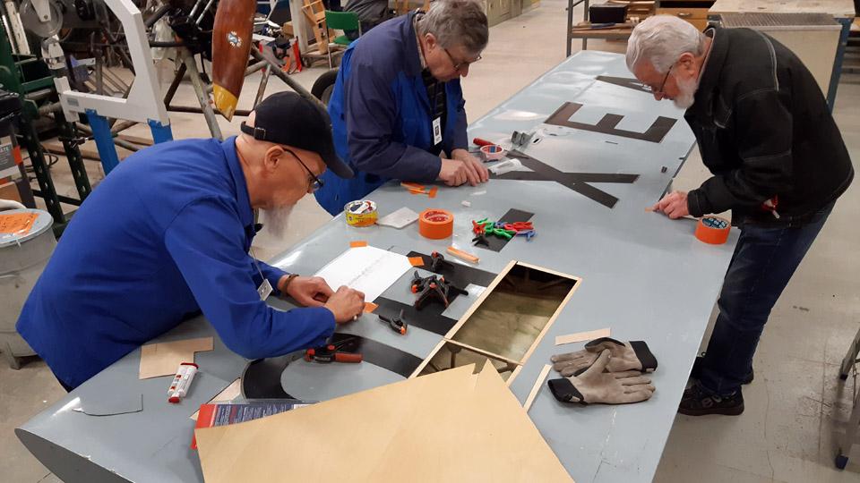
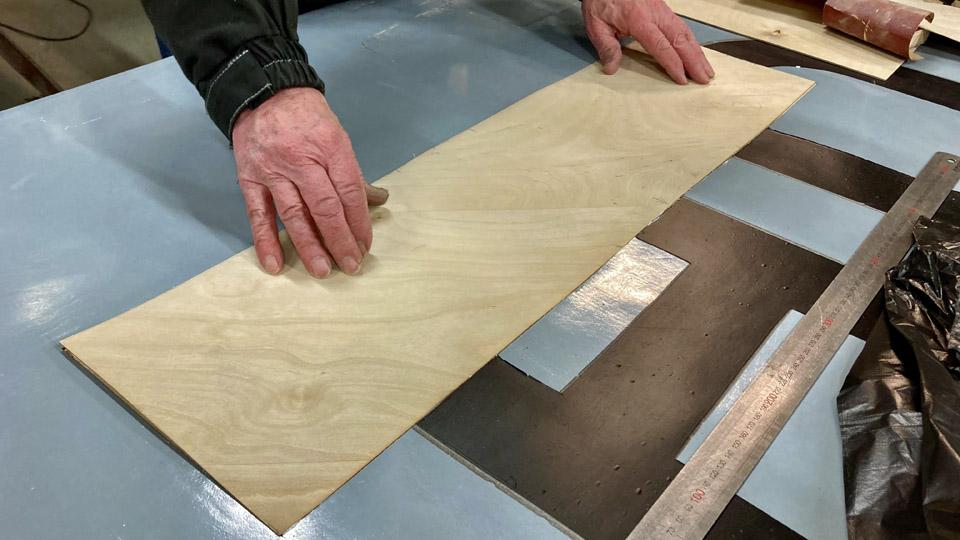
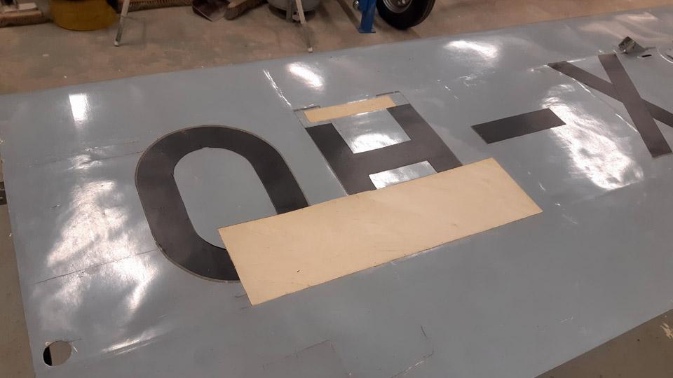
Covering of Ressu's (Snoopy) rudderMaanantai 6.5.2024 - Tuesday Club member When the preliminary tasks concerning the covering of the experimental aircraft Hietanen OH-XEA rudder had been done, the proper covering could be commenced. The rudder covering is done with cotton fabric meant for covering aircraft. The covering will be done the same way it had originally been done in the 1960s.
The covering got started by setting the metal-framed rudder on the fabric, which was spread on the table. The edge of the fabric was wrapped around the right-hand side metal tube of the leading edge and sewed onto it. The sewing was done with thin cotton thread, using a suitable curved or hooked needle.
After the fabric had been sewn to the leading edge right-hand tube, the rudder was turned over on the table, so that the metal frame of the rudder was left under the fabric. The fabric that was attached to the right-hand leading edge, was drawn over the leading edge and left-hand side to the trailing edge the of the rudder, where the lapel of the fabric was left hanging over the table edge.
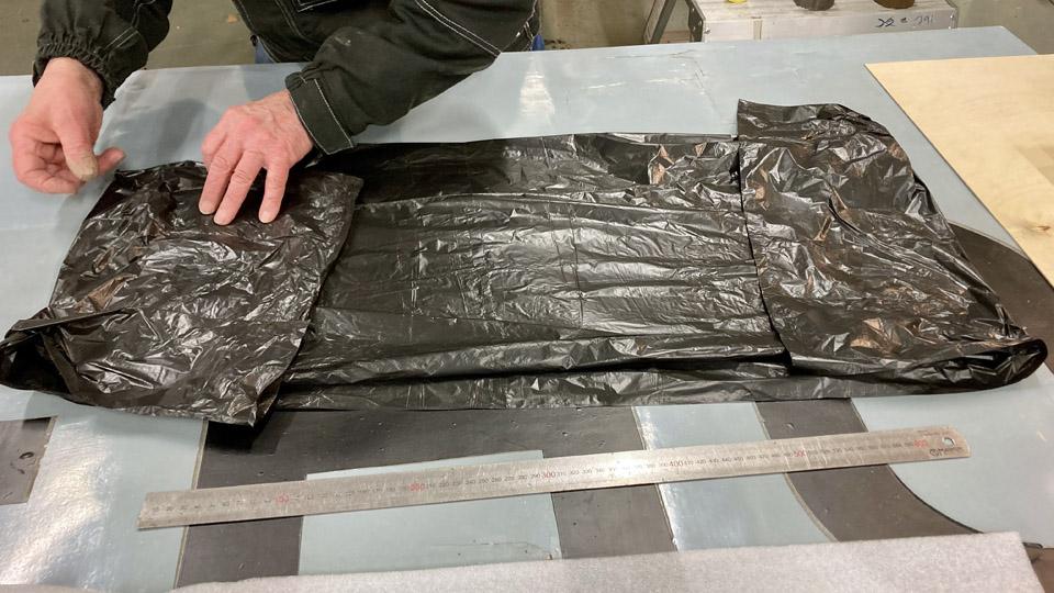
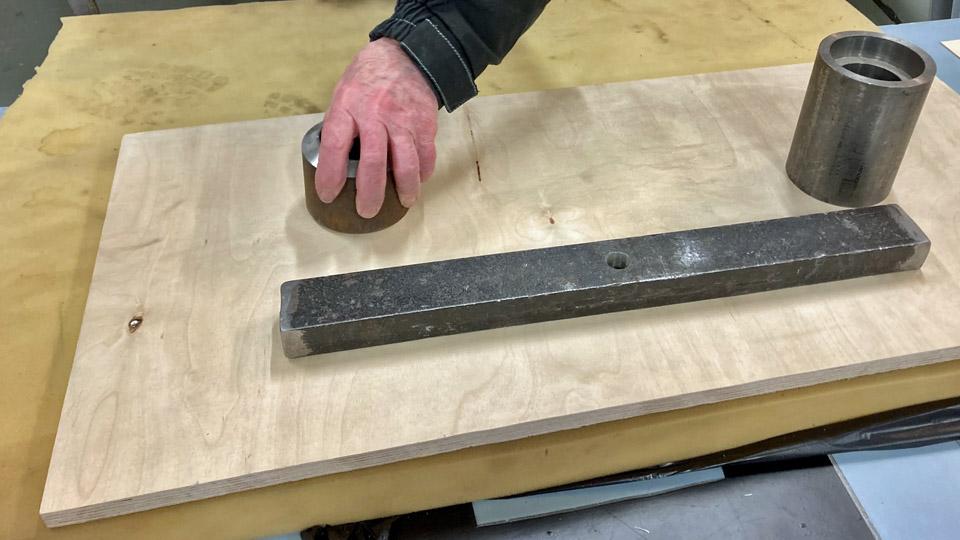
A metal bar was attached to the hem of the fabric hanging over the table edge. With the aid of the bar the fabric, resting on the left-hand side of the rudder, was tightened. At the top and bottom edges of the rudder the lapels of the fabric were tightened with small clamps to the edge of the table. When the fabric was tightened this way, the water tightening of the fabric was started. The fabric was soaked through with boiled water. When drying, the fabric shrinks a little. The proper tightening of the covering fabric will be done after the water tightening with nitrocellulose lacquer.
The tightening lacquering of aircraft covering fabrics is carried out in a process with several phases. The tightening lacquering is started with a 25 % thinned nitrocellulose lacquer. From that the process continues with intermittent sanding to 50, 75,100 -% nitro lacquer. After each phase the fabric is sanded free of the fuzz brought to the surface by the lacquer. From phase to phase the covering fabric will shrink more and more. The end result is a covering fabric tight as a drum head. The sufficient degree of tightening is easy to verify by tapping the surface. It’s customary to pigment or colour red the lacquer with iron oxide powder. This will help to recognize which area has been dealt with the lacquer and which not.
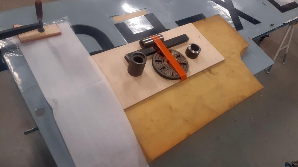
When the water-soaked fabric on the left-hand side of Ressu’s rudder had dried, 25 % thinned NC-Speed nitrocellulose lacquer was applied on the surface of the fabric. As a thinner NC-Speeds’s own Thinner-8 was used. The lacquer was tinted red with red iron oxide powder. After the lacquer had dried, the weights were detached and the rudder was turned around, after which the unlacquered side of covering fabric was drawn tightly under the right-hand side of the rudder. The lapel of the fabric was sewn to the leading edge of the right-hand side metal tube, i.e. the same, where the lapel of the fabric had been sewn in the first place. The covering fabric was now around the rudder like a bag.
Now the right-hand side fabric of the rudder in its turn was water-soaked. After that this side, too, was lacquered with 25% NC-Speed tightening lacquer. After the lacquer had been dried, the rudder’s lower edge, triangular shaped in cross section, was covered by sewing the lapels of the fabric onto the tubes in the rudder’s lower edge.
The tightening of the covering fabric continued with applying a second layer of 25 % lacquer on the rudder surfaces. Because the fabric didn’t start to tighten in the manner we had hoped, the rudder was lacquered a third time over with 25% lacquer. From this point on we advanced in stages to three times applied 50% and twice applied 75% NC Speed lacquering. In this manner a sufficient level of tightness was achieved, so that the fabric strips protecting the stiches of the covering fabric at the edges of the rudder can be fastened. The protecting strips will be glued to the leading, upper, and bottom edges of the rudder. No strip will be needed at the trailing edge because there’s no seam in the fabric there. Of course we could glue a strip there, too, because it would make it more resilient.
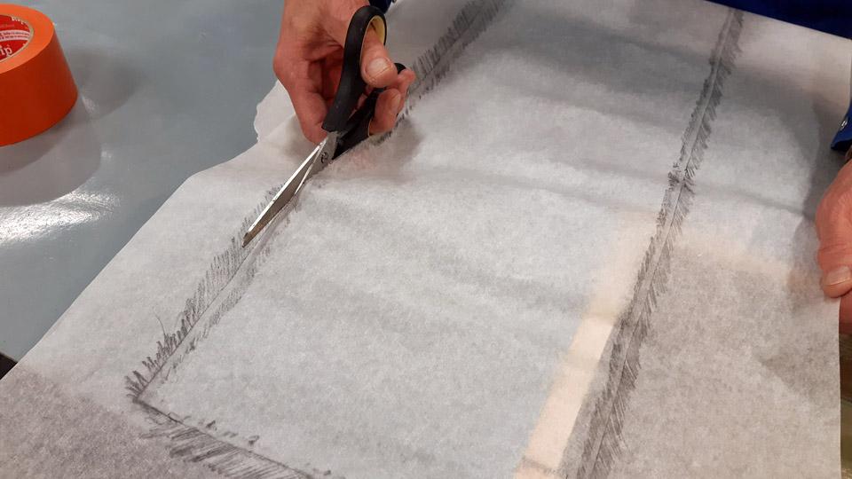
The protective strips were cut off the same covering fabric with which the rudder was covered.
The cutting was done with serrated zig-zag scissors. The serrated edge of the protective strip will stick better to its base, i.e. the lacquered surface of the covering fabric compared to the straight edge.
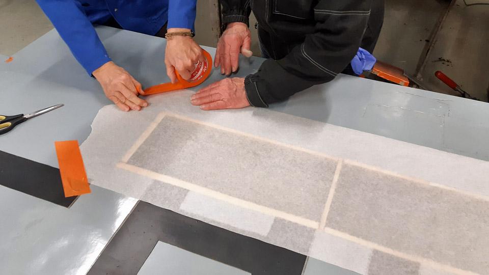
The protective strips were glued to the rudder with 75% nitrocellulose lacquer. First the area of the protective strip was lacquered, after which the strip was pressed onto the wet lacquer. The strip was applied with lacquer so that it became thoroughly soaked with lacquer. The strip was pressed against is base and brushing away air pockets or bubbles from under the strip. At the same time it was made certain that the serrated edges were tightly glued to the surface of the covering fabric.
After the strips had dried, their surfaces were sanded smooth paying attention especially to the serrated edges. The lacquering and sanding were repeated three times, after which the protective strips and especially their serrated edges were worked so smooth, that feeling with your finger gave you no sensation of the strip edge on the surface of the covering fabric.
After fastening the protective strips, the whole rudder was lacquered once with 100% nitrocellulose NC Speed lacquer. The covering fabric of the rudder had now reached the stage where it was as tight as a drum head and thus ready for painting. According to Ressu’s original colour scheme it will be light bluish grey. Photos by Lassi Karivalo. Translation by Matti Liuskallio. |
|
Avainsanat: aviation history, restoration, Tuesday Club, Hietanen HEA-23b, OH-XEA, "Ressu" |
Caravelle right-hand wingtip is finalized with the navigation light globeLauantai 27.4.2024 - Tuesday Club member When the new leading edge had been built to replace the destroyed right-hand side wingtip leading edge on the Caravelle III (OH-LEA Bluebird), we could begin the installation of the navigation light globe into its place on the leading edge. We don’t have the original navigation light globe because it has been destroyed together with the wingtip. We could not find a globe as a spare part either, so we had to make one. We chose to do this by 3D-printing. We used the partly broken navigation light globe from the left wing as a model. A new globe was printed for the right wing and also for the left wing navigation light.
The new navigation light globe was installed on the OH-LEA Bluebird’s left-hand wing earlier in the summer of 2023. The right- hand wing, however, had to wait until March 2024 for its new globe to be put already in early into place after the new leading edge of the destroyed wingtip had been finished.
The 3D-printed navigation light globe is made of stiff plastic, and in the beginning it didn’t fit properly into place. We heated the globe with a hot air blower so that it could be moulded to fit into its mounting on the wingtip. The globe was fastened tentatively on the edges of the mounting with a couple of screws. This was necessary for holding the globe in place while making the fastening frame. The globe is fastened on the aluminium edge of its mounting with a frame. The frame has holes for screws, and it presses tightly against the sides of the globe, and the screws in the frame holes are tightened through the globe edge into the aluminium edge underneath.
Diverging from the original solution, we decided to make the fastening frame for the globe from two parts. This made it easier to build the frame. Nevertheless, the frame we made will cover the most part of the navigation globe edge. A connecting piece will be needed on the top of the globe to connect the ends of the frame.
When the globe had been fastened with a couple of screws, broad paper tape was fastened on its edge. The shape of the globe frame was drawn on the tape. Based on the drawn line, a model for the frame was made of cardboard. The model was taped on a 1 mm thick aluminium sheet, which had already been pre-cut into the frame shape. After this we began to modify the sheet with a cutter to match the shape of the cardboard model.
The aluminium frame was test-fitted into place and modified several times. Gradually the frame reached its final shape and it rested against the lower edge of the globe as §planned. When the desired shape had been reached, the blue plastic film which had protected the aluminium surface was removed from the frame.
A strip of paper tape was fastened on the surface of the finalized fastening frame for marking the location of the fastening screws at regular intervals with a pencil. Holes for the fastening screws were drilled at the marked locations, then the screws were fastened one by one. This made the navigation light globe press into its place between the fastening frame and the edge of the globe mounting. Now the navigation light globe on the right-hand side wingtip was in place.
The last phase was to make the 5 cm connecting piece between the fastening frame ends on the top of the navigation light globe. First a cardboard model was made of the connecting piece. The connecting piece was cut and moulded from aluminium sheet, following the model. When the blue plastic covering had been removed from its surface, the connecting piece was fastened between the fastening frame ends, using two screws with washers. Finally the screws were tightened.
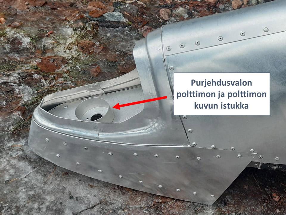
Under the globe, out of sight, is the socket for the navigation light bulb and its green glass globe. The socket was lathed from aluminium and installed into place at the Tuesday Club. The Caravelle’s right-hand side wingtip is ready for housing a powered navigation light, if there is need for it at some point.
Now the Caravelle Bluebird’s right-hand side wingtip had been completed. Re-constructing the destroyed leading edge took a whole year. The wingtip can be delivered to Turku to be assembled on the Caravelle Bluebird, which is on display near the passenger terminal at Turku airport. Photos by Lassi Karivalo. Translation by Erja Reinikainen. |
|
Avainsanat: aviation history, restoration, Caravelle, OH-LEA, Sinilintu, Bluebird, Tuesday Club |
Caravelle's passenger door mechanism is repaired - Part 2Torstai 25.4.2024 - Erja Reinikainen ja Martti Saarinen Until now access to the Caravelle’s cabin has been through the small right-hand side service door and aft stairway. The passenger door operating mechanism has been damaged, and the door can’t be used before the mechanism is repaired. This blog describes the first phase of the passenger door repairs. When the passenger door is opened, it moves first straight inwards and then it is manually lifted along its rails up to the cabin ceiling. The door weighs 53 kilos, so opening and closing is assisted with a counterbalancing system. The system consists of roller chains, steel cables and three bungee cords (rubber ropes), several metres long and located under the cabin floor. There are no spare parts available for this system anymore, so the new parts have been designed and made by the technical team.
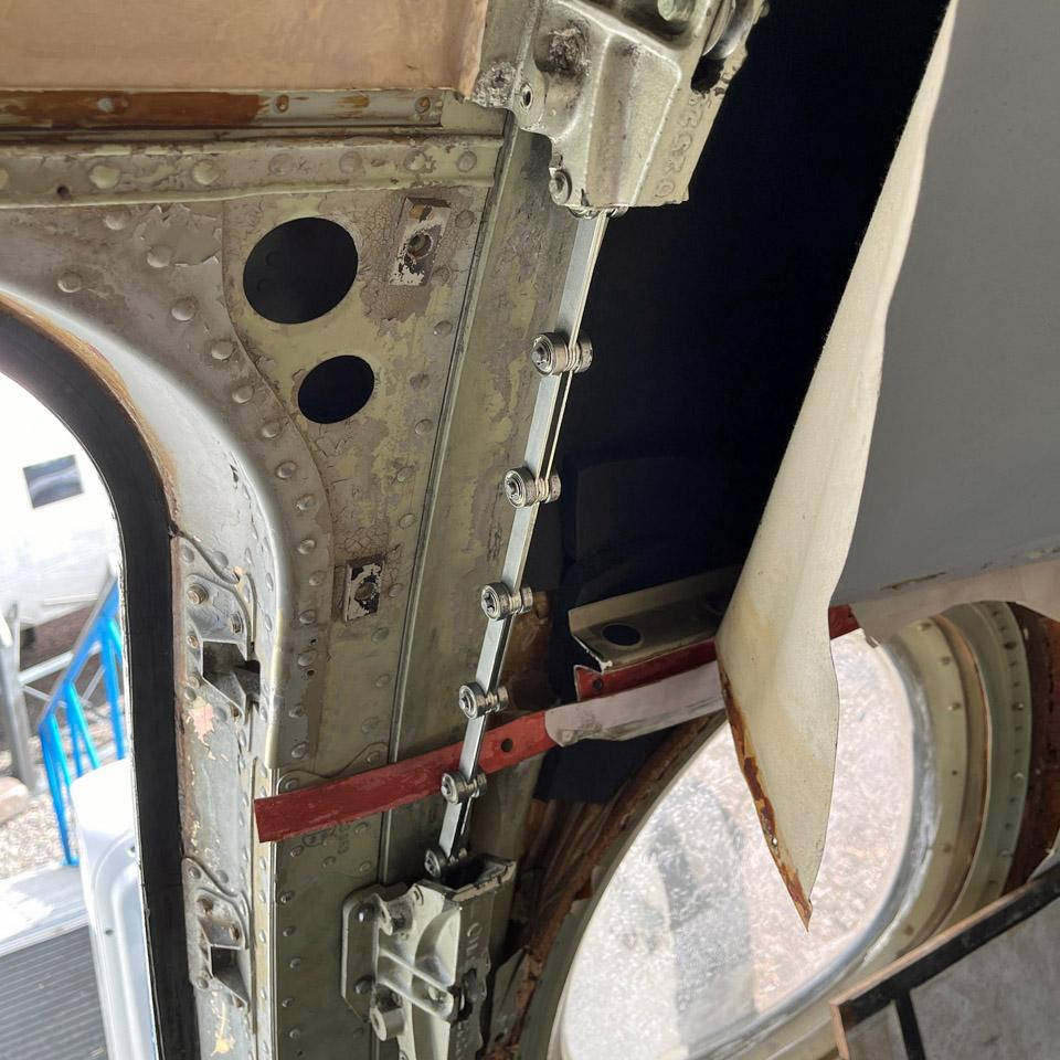
On its visit to Turku on April 12th, the technical team started the door mechanism repair work. The first phase was to install the new roller chains into the door rails (the broken chains had already been removed). The new roller chain is slightly different from the original one and some parts for it were made by order in a laser cutting company, and others ordered from abroad.
When the two roller chains were in their rails, their lower ends were fastened to the brackets on the passenger door and their upper ends to the counterbalancing cables. The roller chains and cables run through the door rails and down to the guides, which are located on the sides of the right-hand side service door. There are 4 guides on each side of the door.
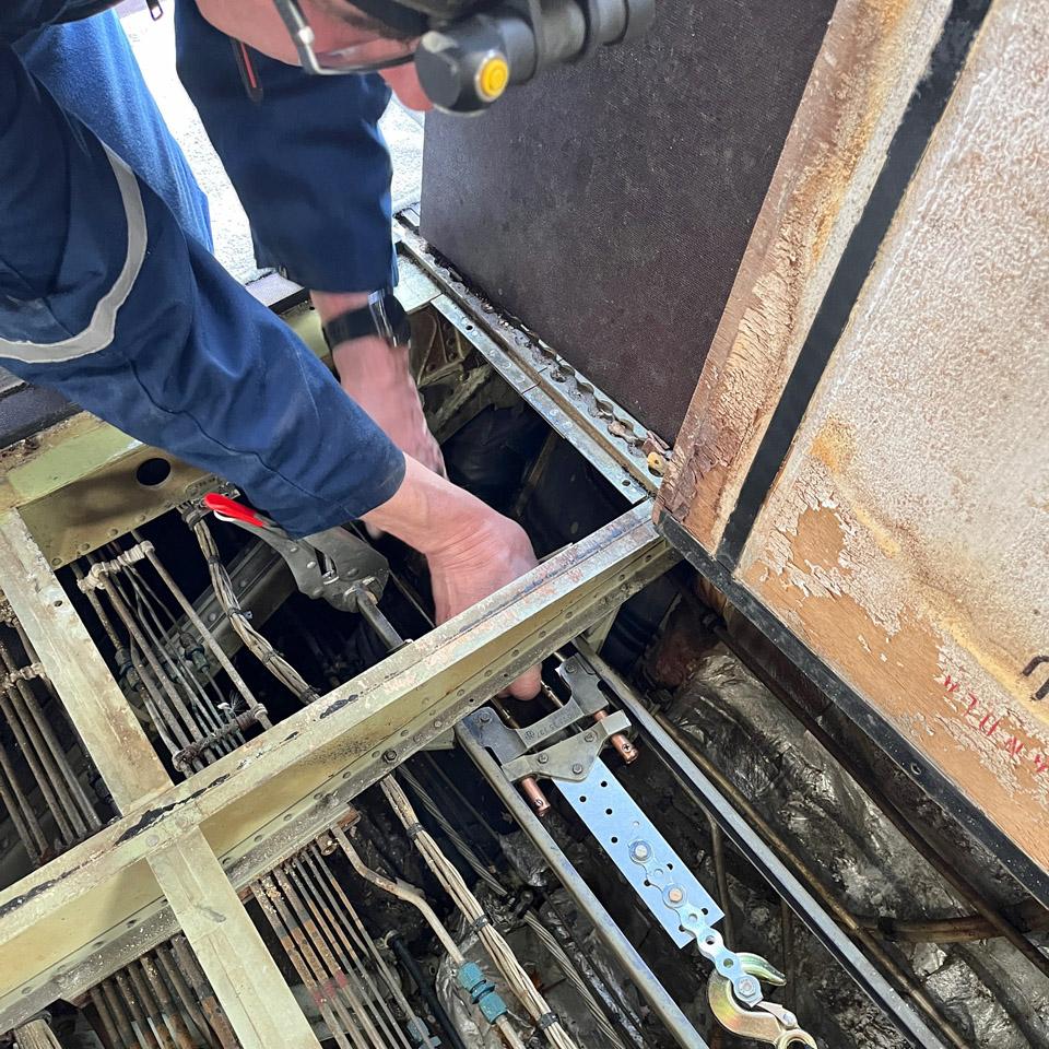
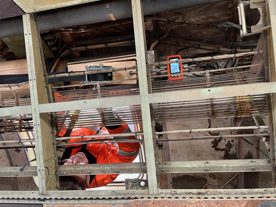
Under the cabin floor, in the side tunnel of the baggage compartment, the cables are connected to the bungee cords on a sliding carriage. The sliding carriage and its stops allow the bungee cords to operate in sequence, as the need for counterbalancing force depends on the position of the door. When closing the door, in the beginning the strength of one bungee rope is sufficient for the required counterbalancing. When the door moves downwards on the rails and is reaching its vertical position, the need for counterbalancing increases. This is when the two other bungee cords join in. The mechanism is complicated and not very reliable. When the Caravelle was in operation, the system needed regular repair and maintenance. The original bungee ropes have become brittle and can’t be used. The technical team is still looking for suitable material to replace the original ropes as the bungee ropes in the regular hardware store are too soft and slack for the purpose.
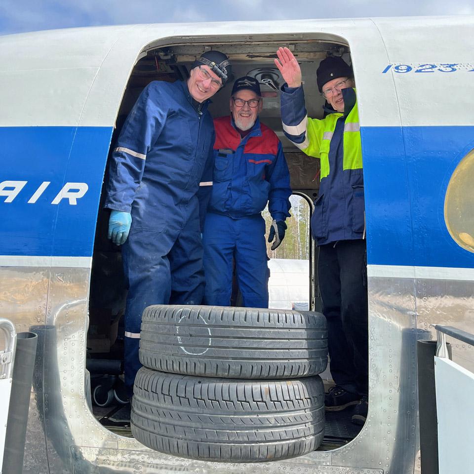
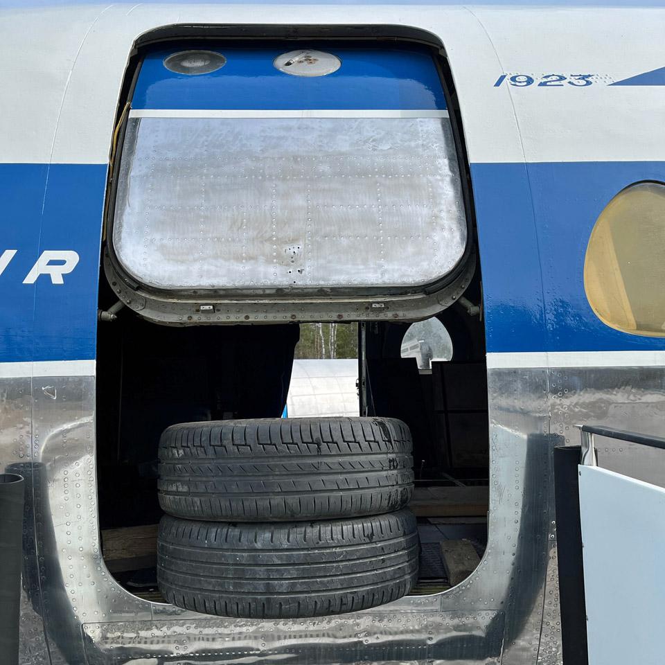
At this point the roller chain and the door function were tested without the bungee ropes by fastening the cables and the sliding carriage to a manual winch. It was not that simple to operate the winch in the cramped space under the floor. The lifting force was measured with the digital scales connected to the winch. The original bungee ropes and their supporting rollers can be seen on the upper right corner of the picture. The test arrangement worked: using the winch the passenger door could be opened, but not fully. At this point the door was secured with a couple or car tyres in the doorway.
The problem appeared to be the roller chain and cable guides, located on the sides of the service door: the new roller chain didn’t move smoothly through the guides. After some discussion the team decided to disassemble and adjust the guides. As a test, the upper guide was disassembled and cleaned, and installed back into place a little bit differently. This helped to solve the problem, so the other guides will be disassembled before the next visit of the technical team when the door mechanism repair will continue.
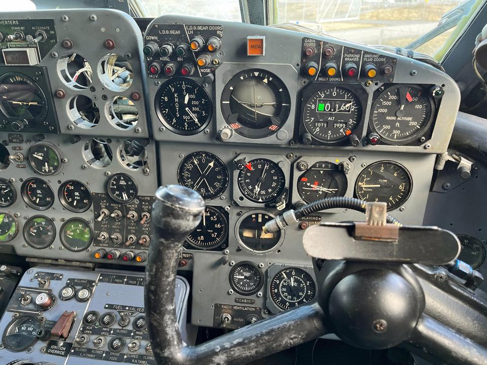
During the day there was also other activity in the Caravelle: three new instruments were installed into the instrument panel on the flight deck. It looks quite good already but there will be some more additions later.
The cabin curtains were unfastened from their popper slides to have them out of the way when the interior work begins. Fortunately the curtains are mainly in quite good condition, but dirty. They will be washed and ironed before putting them back. This won’t be done before the interior work has been completed.
Work was going on outside, too: the SAS prints were removed from the aft stairway before repainting. The best work method has proved to be to heat the painted area first with a blower and the scrape the paint off. Photos by Erja Reinikainen. |
|
Avainsanat: aviation history, restoration, Caravelle, OH-LEA, Sinilintu, Bluebird |
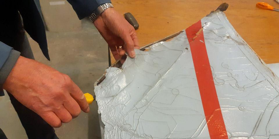
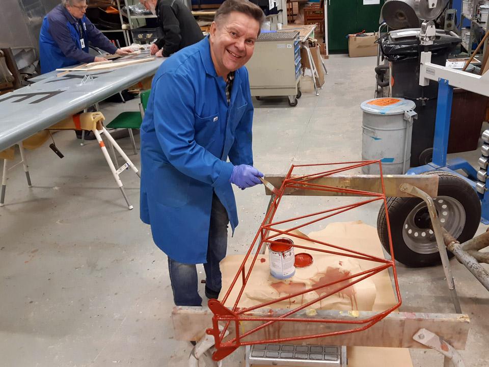
The Ressu (Snoopy) rudder covering preliminary work assignmentsSunnuntai 21.4.2024 - Tuesday Club member The IMY Tuesday club has continued its work with the Snoopy (Ressu). Planned and built by the Hietanen Brothers from Turku, the mixed structure experimental aircraft Ressu from the 1960s is next in line for the rudder’s canvas covered steel tube structure to be restored.
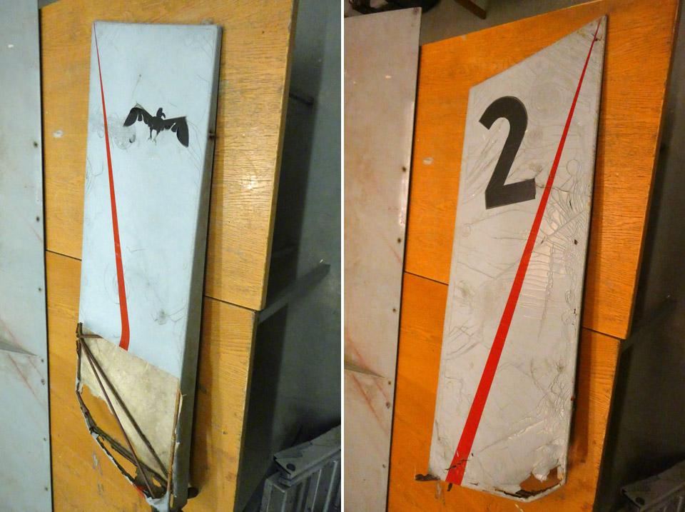
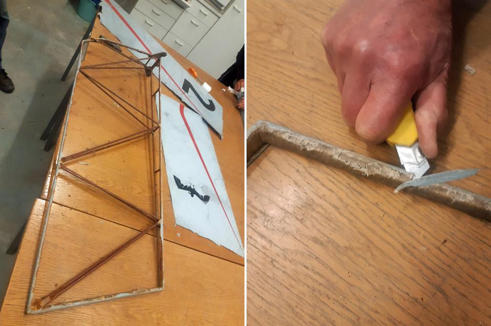
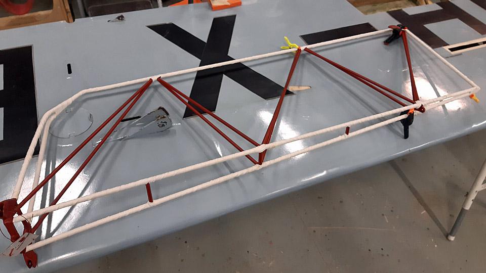
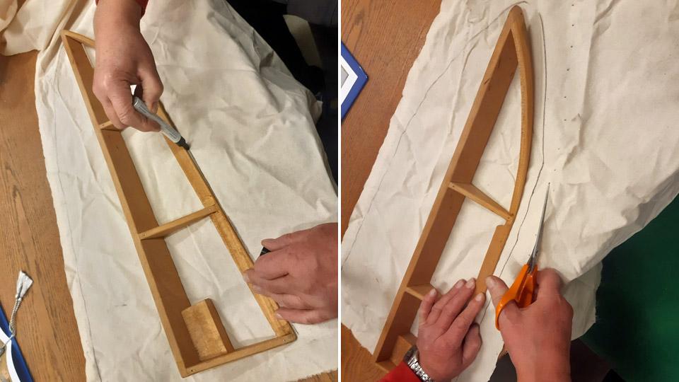
For the restoration the rudder was detached from the fuselage. The fabric covering was in a fragile shape, and the paint finish of the canvas badly crackeled. On the left-hand side the covering is fairly intact, but on the right-hand side a large piece of covering is missing on the lower edge. From this unexpected opening it could be seen that the covering canvas had been sewn onto the rudder frame outer tubes only, but not onto the cross tubes. The outer ring metal tubes had been covered with 20 mm wide cotton edging ribbon, by winding it the tightly along the tube. This was a common way to avoid the covering fabric to be attached to form a direct contact with metal. The fabric, that was sewn to the metal structure, had been tightened drum tight with nitrocellulose lacquer, after which the surface had received a light blue coat of paint. Finally the rudder had been treated with red speed stripes, a black number 2 and a bird figure.
Because the Ressu’s rudder covering fabric was in a bad shape and partly broken, we decided to cover it completely anew, complying the old manner of doing it, however. The old covering fabric had to be detached from the steel frame of the rudder by cutting it off with a knife, because the fabric had glued itself tightly to the edging ribbons around the tubes. After detaching the covering fabric, the edge ribbons around the metal tubes were also removed.
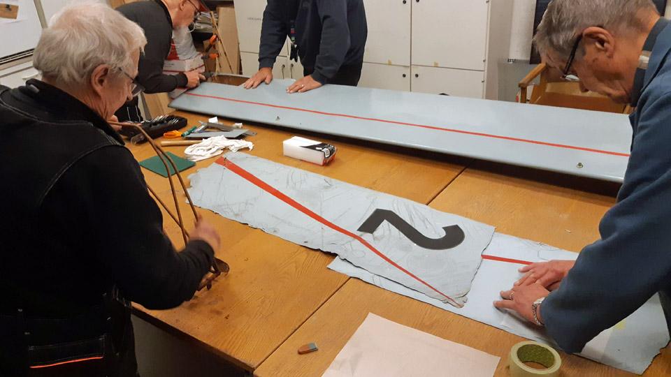
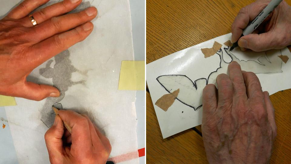
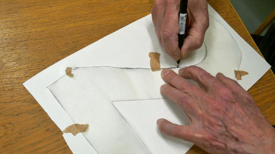
The red stripes of the rudder’s covering fabric and the left-hand side black number two and the right-hand side black bird were copied on transparent rice paper. After that the bird and the number were transferred onto sturdy cardboard to wait for the final transfer of these symbols onto black contact plastic, and their fixing onto the surface of the new covering fabric.
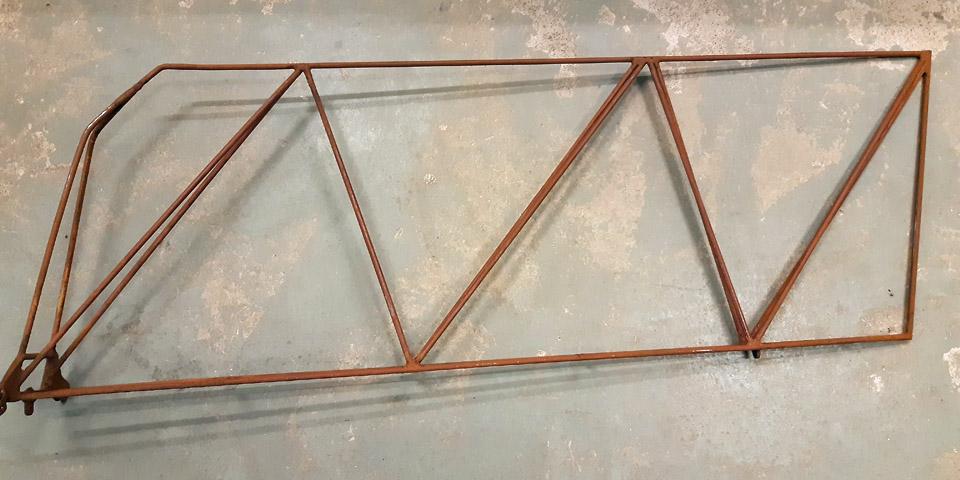
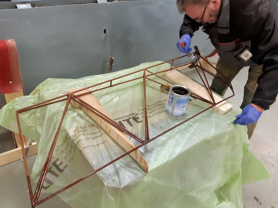
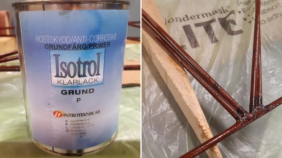
The work with the rudder’s metal structure was continued with doing away with the rust on the tube surfaces. Luckily the tubes weren’t badly rusted or corroded. The rust was sanded off with sanding paper, however, so that the tubes weren’t ground to pure metal. The transparent Isotrol-lacquer can be applied as primer even though the surface is still a bit rusty. The shielding cover of the Isotrol- lacquer will stop the rusting process. During the sanding it had been noticed that the rudder had originally been painted red. The paint had most probably been the red Ferrex, used widely in the 1960s to stop rusting.
The rudder frame structure was primed thinly with the transparent Isotrol -lacquer. Owing to the lacquer, the tube surfaces came out beautifully clear and the red paint applied on the surfaces rose up even more gloriously. After a light buffing, a layer of red Isotol paint was applied on the bright Isotrol lacquer, emulating the original red surface paint.
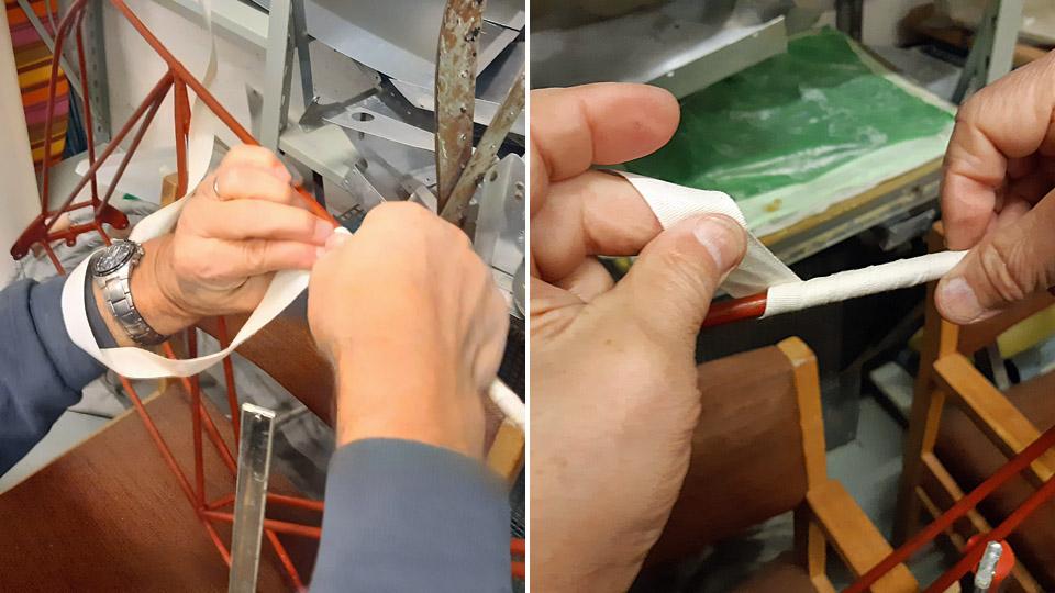
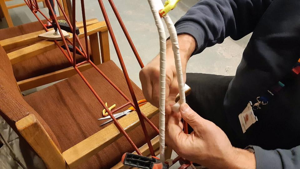
When the rudder frame had dried, we started to cover the steel tubes by winding 20 mm wide cotton edging ribbon around the steel tubes. Thus we’ll prevent, according to the original concept, the covering fabric being in direct contact with the surface of the steel tubes. By hurrying slowly we managed to wrap the cotton ribbon around the outer tubes of the frame. Ressu’s rudder in now ready to begin the fabric covering proper. Photos by Lassi Karivalo. Translation by Matti Liuskallio. |
|
Avainsanat: aviation history, restoration, Tuesday Club, Hietanen HEA-23b, OH-XEA, "Ressu" |
Caravelle's passenger door mechanism is repaired - Part 1Tiistai 16.4.2024 - Erja Reinikainen ja Martti Saarinen Until now access to the Caravelle’s cabin has been through the small right-hand side service door and aft stairway. The passenger door operating mechanism has been damaged, and the door can’t be used before the mechanism is repaired. This blog describes the first phase of the passenger door repairs. When the passenger door is opened, it moves first straight inwards and then it is manually lifted along its rails up to the cabin ceiling. The door weighs 53 kilos, so opening and closing is assisted with a counterbalancing system. The system consists of roller chains, steel cables and three bungee cords (rubber ropes), several metres long and located under the cabin floor. There are no spare parts available for this system anymore, so the new parts have been designed and made by the technical team. On its visit to Turku on April 12th, the technical team started the door mechanism repair work. The first phase was to install the new roller chains into the door rails (the broken chains had already been removed). The new roller chain is slightly different from the original one and some parts for it were made by order in a laser cutting company, and others ordered from abroad.
When the two roller chains were in their rails, their lower ends were fastened to the brackets on the passenger door and their upper ends to the counterbalancing cables. The roller chains and cables run through the door rails and down to the guides, which are located on the sides of the right-hand side service door. There are 4 guides on each side of the door.
Under the cabin floor, in the side tunnel of the baggage compartment, the cables are connected to the bungee cords on a sliding carriage. The sliding carriage and its stops allow the bungee cords to operate in sequence, as the need for counterbalancing force depends on the position of the door. When closing the door, in the beginning the strength of one bungee rope is sufficient for the required counterbalancing. When the door moves downwards on the rails and is reaching its vertical position, the need for counterbalancing increases. This is when the two other bungee cords join in. The mechanism is complicated and not very reliable. When the Caravelle was in operation, the system needed regular repair and maintenance. The original bungee ropes have become brittle and can’t be used. The technical team is still looking for suitable material to replace the original ropes as the bungee ropes in the regular hardware store are too soft and slack for the purpose. At this point the roller chain and the door function were tested without the bungee ropes by fastening the cables and the sliding carriage to a manual winch.
It was not that simple to operate the winch in the cramped space under the floor. The lifting force was measured with the digital scales connected to the winch. The original bungee ropes and their supporting rollers can be seen on the upper right corner of the picture.
The test arrangement worked: using the winch the passenger door could be opened, but not fully. At this point the door was secured with a couple or car tyres in the doorway.
The problem appeared to be the roller chain and cable guides, located on the sides of the service door: the new roller chain didn’t move smoothly through the guides. After some discussion the team decided to disassemble and adjust the guides. As a test, the upper guide was disassembled and cleaned, and installed back into place a little bit differently. This helped to solve the problem, so the other guides will be disassembled before the next visit of the technical team when the door mechanism repair will continue. During the day there was also other activity in the Caravelle: three new instruments were installed into the instrument panel on the flight deck. It looks quite good already but there will be some more additions later.
Photo by Jouko Tarponen. The cabin curtains were unfastened from their popper slides to have them out of the way when the interior work begins. Fortunately the curtains are mainly in quite good condition, but dirty. They will be washed and ironed before putting them back. This won’t be done before the interior work has been completed.
Photo by Jouko Tarponen Work was going on outside, too: the SAS prints were removed from the aft stairway before repainting. The best work method has proved to be to heat the painted area first with a blower and the scrape the paint off. Photos by Erja Reinikainen except if otherwise mentioned. |
|
Avainsanat: aviation history, restoration, Caravelle, OH-LEA, Sinilintu, Bluebird |
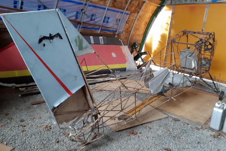
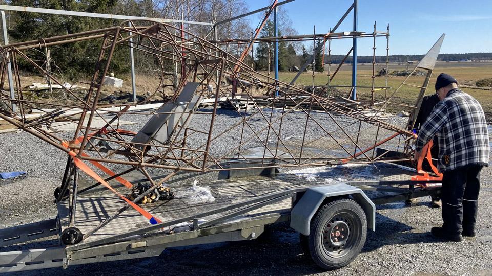
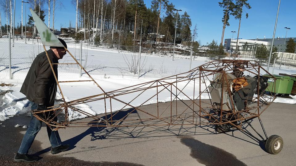
Ressu's fuselage frame moved from Lemu to VantaaTiistai 9.4.2024 - Tuesday Club member On Thursday April 4th, the Tuesday Club task force set off towards Lemu in the Turku region to fetch the OH-XEA “Ressu” (“Snoopy”) fuselage frame to Finnish Aviation Museum to be restored by the Tuesday Club. The OH-XEA is an experimental aircraft, designed and built in the late 1960s by brothers Hietanen, Esko and Ari. Since last autumn we have been working on the restoration of Ressu’s horizontal stabilizer, elevator, rudder, and wing struts. This work will be ready soon and we could pick up the Ressu’s fuselage frame from Lemu to be restored. The Ressu fuselage, stripped entirely of its fabric covering, has been stored in the hall of Martti Mattila, an aviation enthusiast from Lemu. Last autumn we fetched the Ressu’s wings and tail parts from the same place. On our way to Lemu we made a detour via Turku Airport, to Caravelle “Bluebird”, which is on display there. In Helsinki we had picked up a Super Caravelle First-Class double seat frame, which we left to the Caravelle. The aim is to build four rows of seats in the “Bluebird” cabin and an adapted group of First-Class seats. From the Airport we continued to Lemu, where we arrived soon after noon.
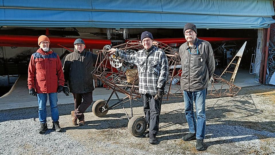
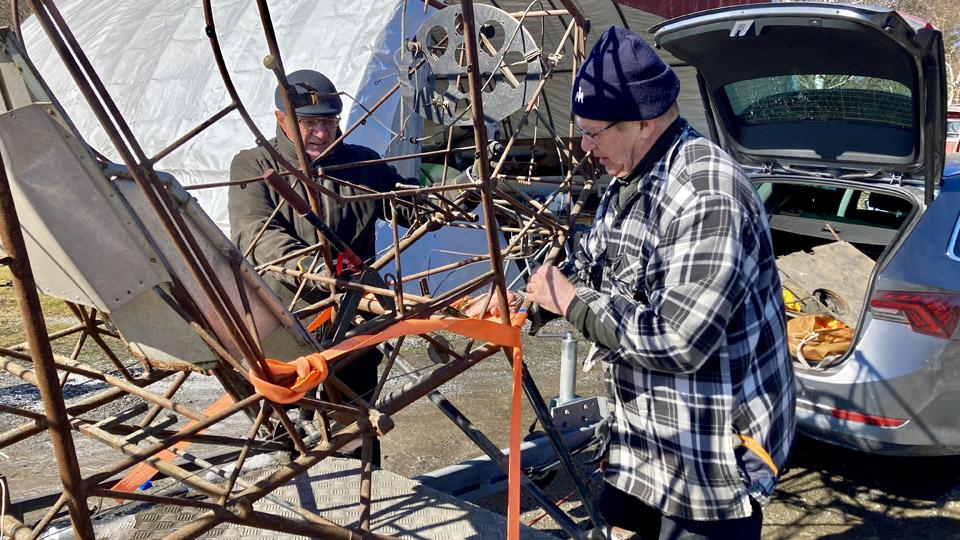
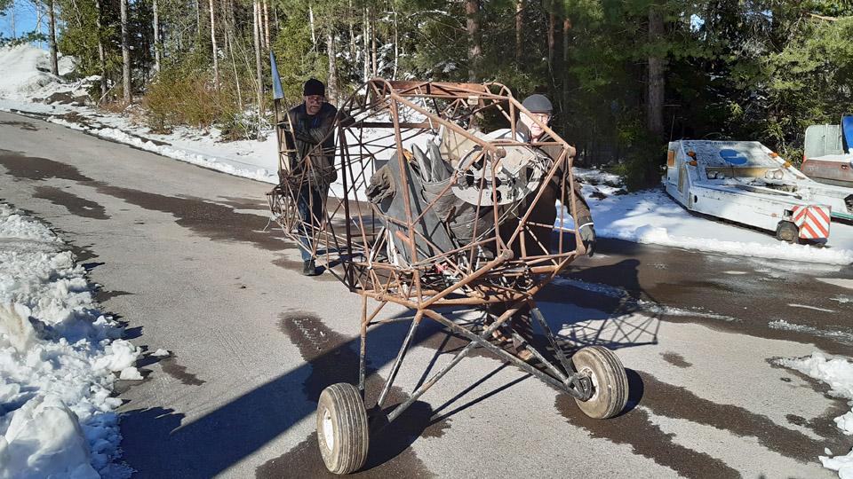
Photo by Martti Mattila. Martti Mattila had already prepared the Ressu fuselage frame for pick up by fastening two wheels with pneumatic tyres, borrowed from a ride-on lawn mower, on the ends of the landing gear axle and by moving the fuselage frame outside the hall. Due to the wheels the fuselage frame was easy to move. The lawn mower wheels are exactly the suitable size for Ressu. Before the fuselage fame was moved next to the trailer to be loaded, the pick-up team posed for a group photo.
Photo by Matti Kainulainen. When the rather light fuselage frame was lifted on the trailer, we noticed that the landing gear with its wheels was too wide to fit inside the trailer sides. We solved the problem by unfastening the wheels and the landing gear fitted just nicely inside the trailer sides, and the fuselage frame rested on the trailer floor on its wheel flanges.
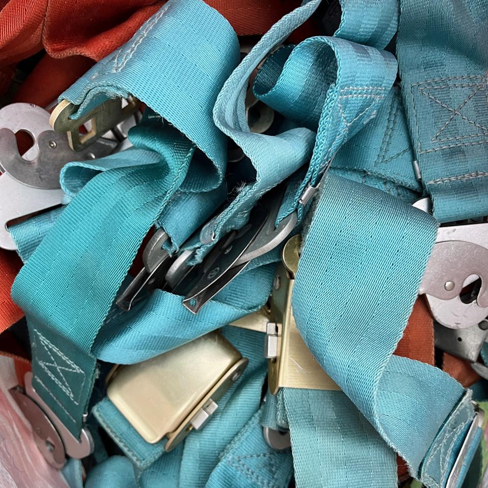
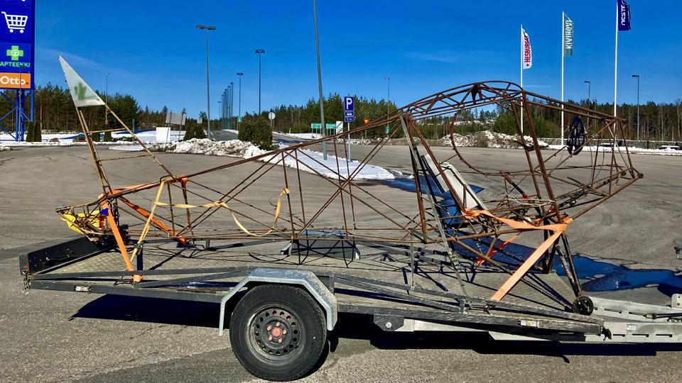
Photo by Matti Kainulainen. We fastened the fuselage frame on the trailer with the nose of the aircraft facing forward. The trailer we had at our disposal was long enough to hold almost the whole length of the Ressu’s fuselage frame. The tail reached just slightly over the tailgate. The fuselage frame was secured tightly on the trailer, front and aft, using cargo straps. We topped up our cargo by adding a security banner on the tail. We also loaded the rest of the Ressu stuff from Mattila’s hall, such as the cockpit plexiglass windows and the seat belts. Many thanks to Martti Mattila for accommodating Ressu and its parts in his hall since last June.
Photo by Matti Kainulainen. We spent some time with Martti Mattila, listening to him talking about his ongoing aircraft engine project. Based on what we heard, we can say that Mattila is a person with multiple skills when it comes to aircraft engines and aircraft in general. He has designed and built an aircraft and he also owns an airworthy engine-Lerche.
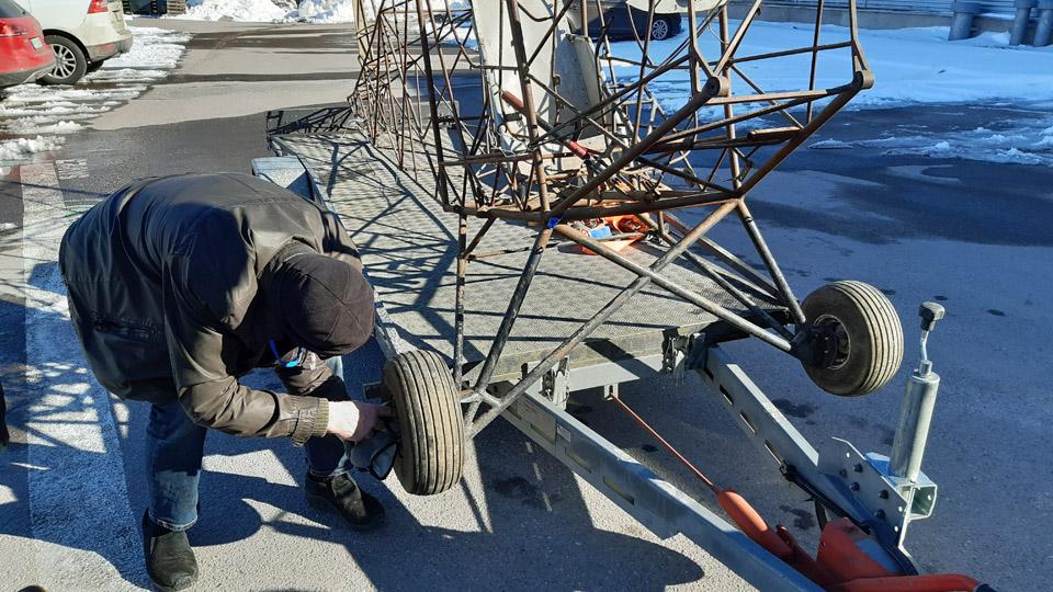
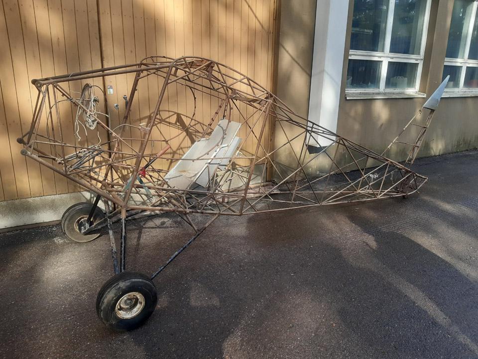
It was time to head back to Vantaa and the Finnish Aviation Museum, where we arrived late in the afternoon. On the museum yard we unfastened the cargo straps from Ressu’s fuselage frame and reassembled the wheels on the landing gear. Then we lifted the fuselage frame from the trailer on the asphalt-covered museum yard and pushed it on its wheels in front of the restoration workshop. As the Ressu’s fuselage frame will remain outside for the time being, we wrapped a tarpaulin around it to protect it from rain.
The Ressu’s fuselage frame is now ready to face the restoration procedure of the Tuesday Club. The first actual work item will be to clean the rusty frame tubes of the fuselage frame, stripped of its fabric covering. Then the tubes will be painted with protective Isotrol paint. Photos by Lassi Karivalo except if otherwise mentioned. Translation by Erja Reinikainen. |
|
Avainsanat: aviation history, restoration, Tuesday Club, Hietanen HEA-23b, OH-XEA, "Ressu" |
Caravelle's overhead storage shelf is movedTiistai 2.4.2024 - Ismo Matinlauri The interior work of Caravelle III, restored as Finnair OH-LEA Bluebird, started in March after the winter break. The first work item was to move the rear part of the left-hand side overhead storage compartment to the front RH side. (In this case the compartment is actually a shelf, and it will be called that in this blog.) On the right-hand side all overhead storage shelves and the ceiling structure have been dismantled in Sweden for the needs of the local Caravelle III SE-DAI. Our aim is to build a part of a passenger cabin to the front part of the fuselage, with four rows of seats. For this purpose the overhead storage shelf had to be disassembled from the rear part and installed to the other side in front. The rear part of the cabin will be an open space for future events and exhibitions. Disassembling the overhead storage shelf proved to be an arduous operation. This seems to be the first area in the Caravelle where screws have not been used sparingly. Obviously the shelf has not been meant to be disassembled regularly during maintenance work. Dozens of small screws had to be unfastened and on top of that, four locking bolts had to be unfastened through the passenger service unit. We had to build a long-handled tool specifically for this purpose.
Fastening battens for the overhead storage shelf were fastened on the RH side, starting from the service door. The lower aluminium batten could be moved but the upper batten proved impossible to unfasten and move, so we decided to use a wooden batten instead.
Reassembling the overhead storage shelf happened as the disassembly but in reversed order. First we fastened the row of air conditioning and loudspeaker panels into place.
The fasteners of the overhead storage shelf had to be modified to fit into their new location. The original spacing of the fasteners didn’t fit because the shelf had to be turned around to assemble it to the other side.
The final fastening of the shelf was done through the passenger service unit (PSU). This time the fastening bolts were replaced with self-drilling screws. We decided not to move the brackets for the fastening bolts, we estimated the screws to be sufficient.
Above the overhead storage shelves we stretched the covering material we had taken down from the other side. Now the front part of the cabin looks identical on both sides. Finally we installed the metal grilles to cover the air-conditioning and loudspeaker panels.
We had been doubtful about moving the overhead storage shelves because of the amount of work and breaking the existing structure. Actually disassembling the shelf proved to be the most difficult and the most time-consuming phase. After that the reassembly into the new place was quite straight-forward. There will be a partition at both ends of the shelf so that the cut ends of the shelf will be covered. Building the partitions will be another story and we will come back to that later. Photos by Ismo Matinlauri. Translation by Erja Reinikainen. |
|
Avainsanat: aviation history, restoration, Caravelle, OH-LEA, Sinilintu, Bluebird |
The Caravelle right-hand wingtip leading edge is completedKeskiviikko 27.3.2024 - Tuesday Club member Owned by Aviation Museum Society Finland and now on display at Turku Airport, the Caravelle lll (OH-LEA Sinilintu, Bluebird) has had its damaged right-hand wingtip leading edge restoration completed. The wingtip in the Caravelle is a separate entity, which can be detached from the wing. For the sake of simplicity, I’ll use the term wingtip for this structure in the future.
The last task in building the new leading edge for the wingtip was to rivet the edges of the upper and lower covering sheets to the centre line of the leading edge. The edges of the covering sheets meet at the centreline of the leading edge. Otherwise the covering sheets of the new wingtip had already been riveted in the wingtip structure.
To be able to rivet the covering sheet edges on the leading edge centreline, the sheet edges were tightened against the leading edge using a cargo strap, tied around the wingtip. After this, rivet holes were drilled at both ends of the sheets and the edges were riveted on the centre line with pop rivets.
It was noticed that a gap of 1-4 mm was left between the edges. The edges of the sheets therefore didn’t reach each other to form a butt joint. It was decided to cover the gap with an aluminium covering strip, running along the leading edge centre line.
To make the covering strip, an 8 cm wide and 40 cm long aluminium strip was cut out of 1 mm thick aluminium sheet to conceal the seam between the covering sheets. The aluminium strip was shaped to the curved form of the leading edge by shaping it against a suitable size iron tube. The concealing strip was arduous to shape because the wingtip leading edge slopes to various directions. The strip was, therefore, moulded phase by phase, fitting it to place at times. Thus the concealing strip was made to press tightly against the leading edge ridge.
Now the blue plastic films protecting the aluminium sheet could be removed and start the riveting of the covering strip. For the riveting the covering strip was tightened to place at both ends with a cargo strap. Masking tape was applied to both ends of the covering strip to mark the places of the pop rivets. The places were marked on the surface of the tape at even spaces with a compass and pencil, and the holes for the rivets were drilled accordingly.
We discussed what would be the best order to rivet the covering strip, so that it would best confirm to the shape of the wingtip leading edge. We ended up in starting the riveting from the rear end of the covering strip, proceeding rivet by rivet towards the wingtip. In doing so, the covering strip riveted itself tightly to the wingtip leading edge. Finally, the edges of the covering strip were tapped with a hammer and a piece of wood to press it still more tightly to the underlying surface of the covering material.
The demanding task of rebuilding the destroyed wingtip leading edge of the Caravelle III was now ready. Let’s not forget the fitting of the 3D-printed navigation lamp cover to its place in the leading edge tip. Photos by Lassi Karivalo. Translation by Matti Liuskallio. |
|
Avainsanat: aviation history, restoration, Caravelle, OH-LEA, Sinilintu, Bluebird, Tuesday Club |
Covering the Link Trainer aileronsMaanantai 18.3.2024 - Tuesday Club member The wing refurbishing of the South-Karelian Aviation Museum’s Link Trainer has moved on to the covering stage. At first we set on to covering the ailerons. One aileron was original and the other built at the Aviation Museum Society’s Tuesday Club to replace the missing aileron. Stripped of its covering, the repaired original aileron and the rebuilt aileron were covered with a special cotton fabric for covering, bought from Switzerland at Craftlab.
The covering was commenced by setting the aileron on the covering fabric and drawing the shape of the aileron on the fabric with a felt pen. The fabric was cut with a wide margin, taking into consideration the actual space for working. The fabric was folded around the aileron, so that the lapels met at the trailing edge. The lapels were fastened together with wig pins, at the same time tightening the fabric on the aileron. T-headed and long wig pins are very handy for this purpose. The pins were acquired from a Chinese on-line shop.
After the lapels of the covering fabric had been fastened to each other with pins, we were facing with tightening the fabric with water. Water tightening is the first phase to make the covering fabric tight. In the process the warp and weft already shrink somewhat, i.e. the fabric pre-tightens around the aileron. For water tightening the water was boiled. By boiling the water it will be disinfected, so that organic impurities won’t infect the fabric, which could cause the fabric to mould. Well, in this case the boiling wouldn’t have been necessary, because we aren’t dealing here with an airworthy device. After the water had cooled down, the fabric was thoroughly soaked.
After the fabric had dried, the proper tightening was commenced. It will be done with nitrocellulose lacquer, which causes the fabric to become as tight as a drumhead. As a lacquer we used NC-Speed nitrocellulose lacquer and as thinner Ohenne 8. Red iron oxide was mixed into the tightening lacquer as a pigment. It is customary to colour the tightening lacquer, so that you can keep track of which areas have been dealt with and which haven’t.
25 % lacquer.
50 % lacquer. The tightening coats of lacquer for the covering fabric will be applied in phases by starting with diluted lacquer and ending up with undiluted lacquer. The Link Trainer’s ailerons were applied at first with two layers of 25% lacquer, followed by two applications of 50% lacquer, one application of 75% lacquer and to finish it all an application of undiluted nitrocellulose lacquer. The lacquered surfaces were sanded between applications for the fuzz, which was stood up by the lacquer.
After the application of 50% lacquer, the fastening pins of the covering fabric were removed. At the same time the extra fabric lapels’ surplus to the trailing edge were cut off with a Stanley knife. This was possible, because the covering fabric was glued firmly enough to the trailing edge of the aileron, the ribs, and other parts of the aileron structure. The trailing edge will be sanded smooth, and a serrated cotton strip will be glued to it to strengthen it.
75 % lacquer. In this connection it must be noted that in case of an airworthy aircraft, the covering fabric would have been sewn to the ribs of the aileron, the same way as the fabric would have been sewn to the wing ribs. In not covering the ailerons and the wings we decided to cut corners, so in this case skip sewing the fabric to the ribs. This had been the case with the damaged covering fabric we stripped off the wings.
The tightening lacquer for one aileron is ready and waiting for to be painted beige. The other aileron will receive a few more applications of lacquer, before its fabric will be as tight as a drumhead. Photos by Lassi Karivalo. Translation by Matti Liuskallio. |
|
Avainsanat: aviation history, restoration, Tuesday Club, Link Trainer |
Damages in the Ressu (Snoopy) plywood covering repairedTiistai 12.3.2024 - Tuesday Club member The restoration of the experimental aircraft (OH-XEA) “Ressu” has so far concentrated on the work with repairing the holes and damages in the plywood covering of the wing halves, ailerons, horizontal stabilizer, and the elevator. This job has now been finished as far as patching goes.
There were about twenty holes and damaged areas in the plywood covering. Part of them being tiny pinpricks, but some were damages measuring tens of centimetres. As patching material, 0,9 mm aircraft plywood was used. To patch small holes, Ressu’s original plywood with a coating of paint was used. We obtained it in connection with clearing the large damaged areas in the wing. In patching the holes in the Ressu plywood covering, we followed the same proven method throughout. In this blog the patching of a largish damage on the lower surface of the left-hand wing will be presented as an example.
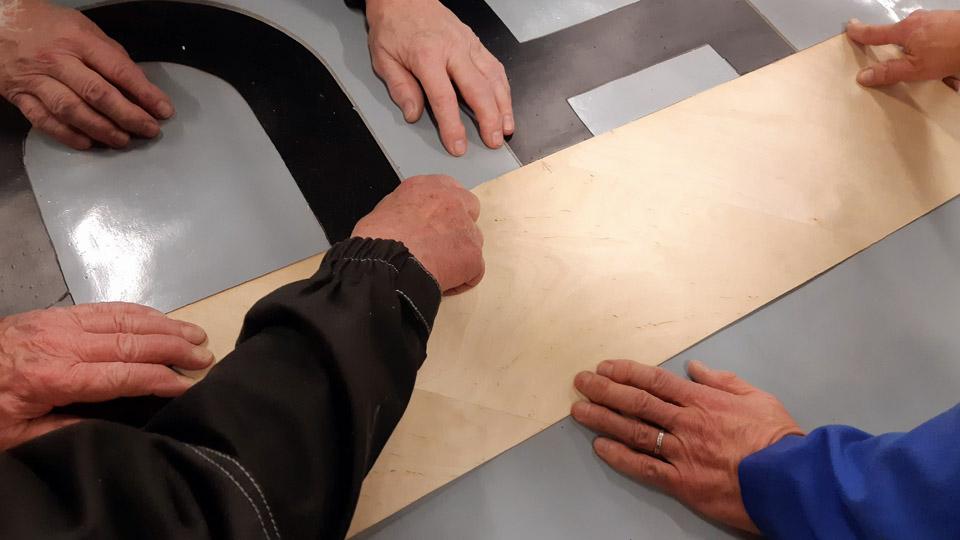
A hole, or an area of a larger damage, was sawn open to a square or rectangular shape. In sawing, a “Kugihiki”, or a so-called Japanese saw was used, which is an excellent tool for sawing thin plywood. Supporting battens were glued under the sawn edges, so that about 1 cm protruded from the inside of the opening. The plywood patch to cover the opening will be glued on these supporting battens.
For gluing the supporting battens and the plywood patches, moisture resistant Erikeeper Plus or Casco Outdoor glue for wood was used. Before gluing the support battens, the protective lacquer was ground off the edges of the underside of the covering plywood. Thus the glue sticks better on the underside of the covering plywood. The support battens were pressed onto the edges of the underside covering plywood with small clamps. Work was also in progress with other holes in the wings, simultaneously with this large opening underside the left-hand side wing.
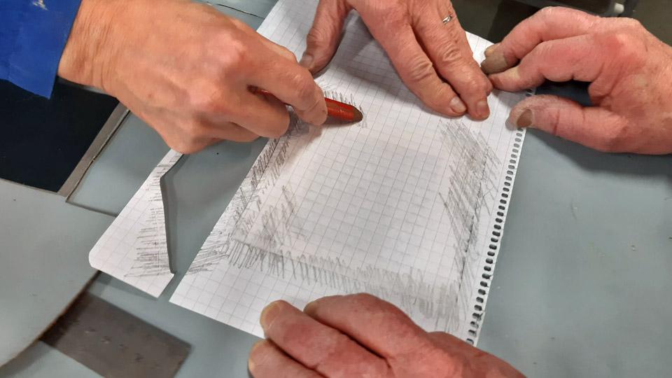
After the glue had dried, a sheet of thin paper was fastened over the whole opening to be patched. The plywood edges of the plywood opening were “smudged” with a pencil so that it became visible on the paper, thus producing an image of the edge line of the opening. The paper was cut along the now visible opening edge in the plywood. So we had a model to cut the right size of a patch. The paper was superimposed on a sheet of plywood and, hey presto, after this model a plywood patch we needed was cut out of the sheet.
The cutout piece of plywood was fitted in place on the support battens. We marked with arrows the places where the plywood patch still needed filing at the edges, to get the patch press itself in a butt-joint manner against the edges of the opening. When the plywood was in place, glue was spread on the support battens, and the plywood was pressed against the battens.
The gluing of the plywood patch was secured by putting a sturdy plywood sheet on the patch and iron weights piled on it. At the lowest a sheet of foam rubber was placed to distribute the weight evenly.
Before laying the weights, a layer of protective plastic was spread over the patch, to prevent extra glue from seeping off the seams of the plywood patch and possibly sticking to the foam rubber sheet. When both the foam rubber sheet and the sturdy plywood sheet were in place, iron weights were piled on the plywood sheet. We noticed after the glue had dried and the weights and the plywood sheet were removed, that the plywood patch had settled very neatly in place. Photos by Lassi Karivalo. Translation by Matti Liuskallio. |
|
Avainsanat: aviation history, restoration, Tuesday Club, Hietanen HEA-23b, OH-XEA, "Ressu" |
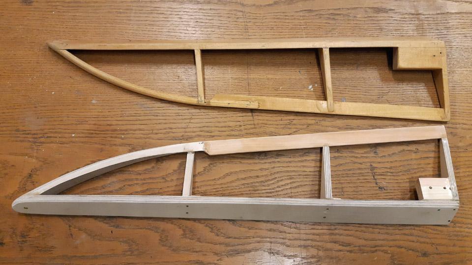
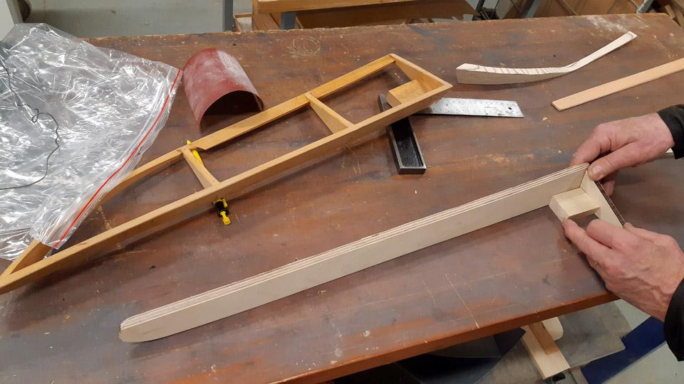
Building of the missing Link Trainer aileronSunnuntai 10.3.2024 - Tuesday Club member The restoration of the Lappeenranta based Karelian Aviation Museum’s Link Trainer wings is underway at the Aviation Museum Society’s Tuesday Club. Our main work is to refurbish the wings and cover them again. Furthermore the missing aileron from the left-hand wing had to be built. As a model we used the right-hand wing aileron, which was stripped of its covering.
Photo by Kimmo Marttinen.
Photo by Lassi Karivalo.
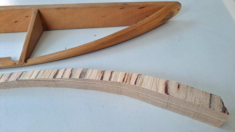
Photo by Lassi Karivalo. We started to build the aileron from strips of wood according to the original. However, we noticed after a few days that the finished parts of the aileron didn’t keep their form, but there were distortions. The material we used wasn’t good enough. We ended up with a solution different from the original by building the left-hand aileron mainly from plywood, which keeps its form well. The decision facilitated our work also so that the curved trailing edge tip had originally got its form from strips of wood soaked in water. Making the curved part of the aileron from plywood will be easier.
Photo by Lassi Karivalo.
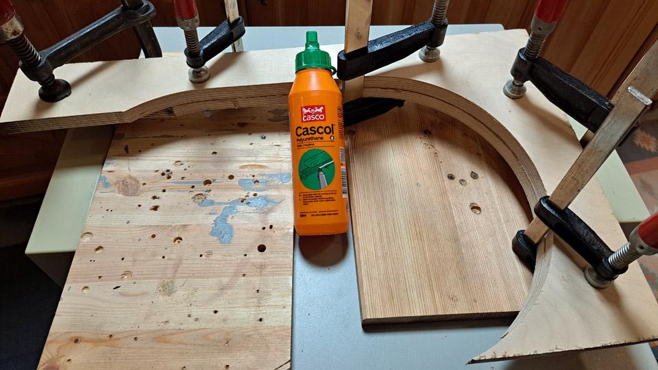
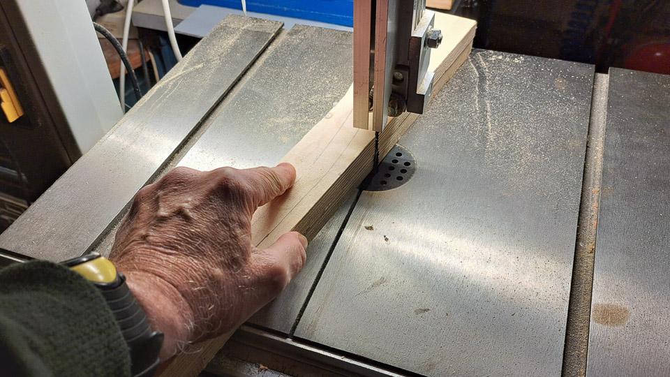
We started making the aileron from the curved tip of the trailing edge. In order to get thick enough plywood to build the trailing edge tip, we glued two sheets of plywood together. After the glue had dried, a picture of the right-hand aileron’s curved trailing edge was drawn on the plywood. The plywood was sawn along the drawing line, to give us a blank for the left-hand aileron trailing edge. The blank was shaped tentatively to its form.
Next we made from plywood the left-hand aileron’s leading edge, which could be called the spar of the aileron. We sawed it from 6 mm thick plywood according to the model given by the right-hand aileron. The leading edge is not at right angles to the wing base. The correct angle (98,3 degrees) was defined from right-hand aileron’s leading edge. The left-hand aileron’s leading edge base was ground to that angle. The leading edge batten was now ready.
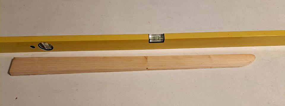
The necessary three triangular ribs were made of plywood according to the right-hand wing aileron ribs and angles. In the same way some thin 3 mm strip of pine was found, from which the straight stem of the trailing edge was made. The trailing edge stem will be joined according to the original model with a 5 cm long glue joint to the curved tip of the trailing edge batten.
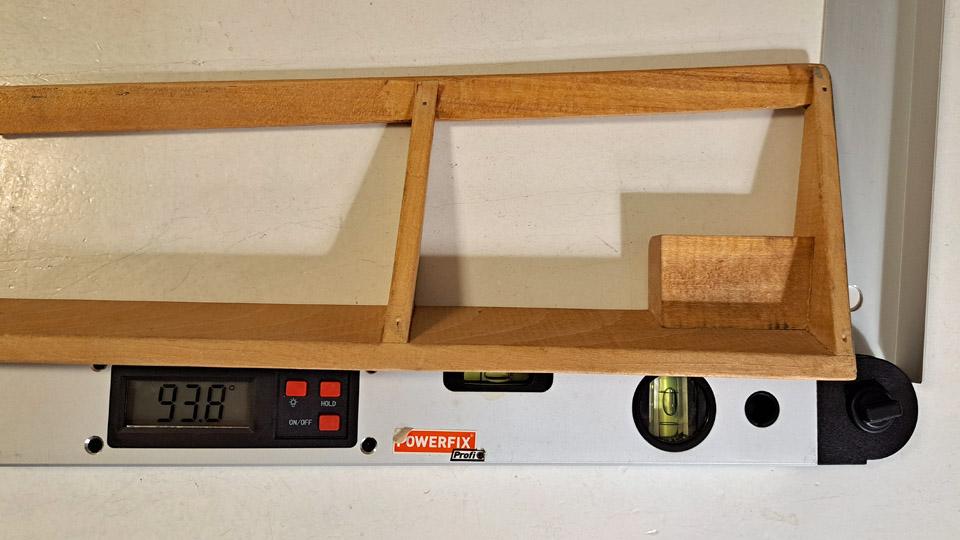
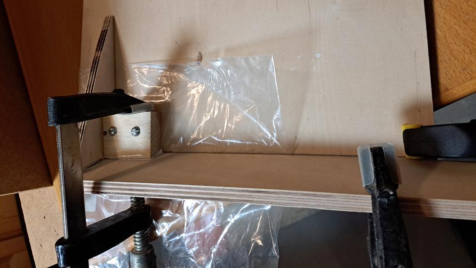
When all the components of the aileron had been made, the construction of the aileron was started. The compilation was commenced with the leading edge and the ribs that were glued to it. As a gluing platform sturdy plywood was used, onto which a guiding piece with an angle of 93,8 was fastened. The leading edge batten was fastened with clamps to the guide piece and its sturdy platform. First the aileron’s root rib was glued into place and after that the two other ribs. The gluing was secured with two screws. The aileron had already got its basic form.
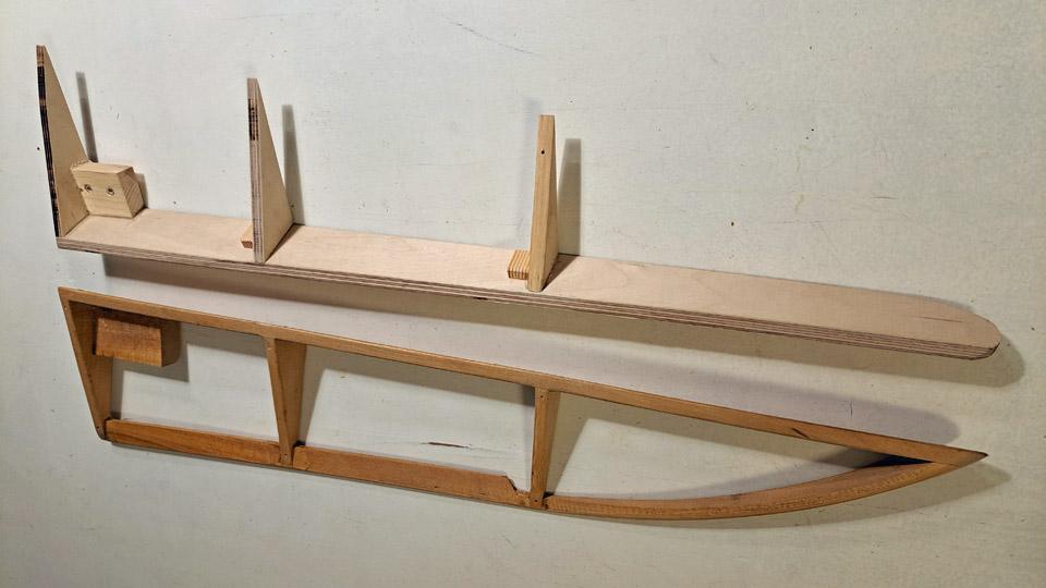
The trailing edge of the aileron was still missing. First the straight thin stem of the trailing edge, which was shaped from a batten of wood, was glued to the ribs. Last to go to place was the curved tip of the trailing edge. At the same time the tip and stem were joined at the rib with a glue joint. The rib also strengthens the glue joint. Because the curved tip of the trailing edge had only been tentatively ground, the tip was ground to final form after the glue had dried.
The missing aileron of the Link Trainer was structurally finished. The aileron will be covered and painted in accordance with the covering of the Link Trainer wings. Photos by Pauli Jokimies except if otherwise mentioned. Translation by Matti Liuskallio. |
|
Avainsanat: aviation history, restoration, Tuesday Club, Link Trainer |
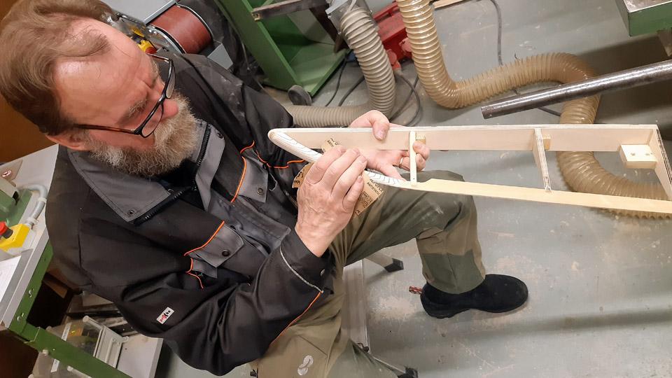
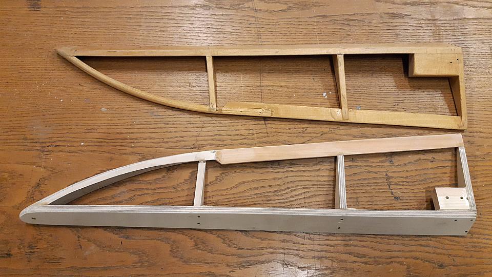
To the sunny south by Super CaravelleMaanantai 26.2.2024 - Erja Reinikainen I wrote in my travel diary on June 22nd, 1966: “The airplane is still on the ground, the engines are running. … We have been in the air for quite a while now. We had lunch and we will be in Warsaw in about 30 minutes. … We took off from Warsaw a long time ago and are flying high above the clouds. Soon we will land in Constanta. We will go by bus from the airport to Hotel Lotus”. We were on a holiday trip to Mamaia beach resort in Romania, on the Black Sea coast. I was 10 years old. The aircraft was Finnair Super Caravelle, but I haven’t noted its registration, and it can’t be seen in the photographs. On the way there and coming back we stopped in Warsaw to refuel. In the same diary there are stories from a trip on the Swedish charter airline’s Internord DC-6 from Helsinki to Naples and back in 1967. Flying over the Alps on a sunny day was an experience for a child from Finland where there are no mountains: “Ahead of us there are magnificent and beautiful mountains! The majestic Alps with their wonderful valleys glide by”. Some superlatives from a 11-year-old.
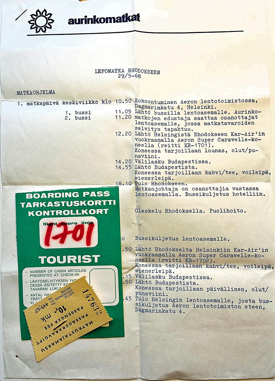
Between the diary pages there is a leaflet by Aurinkomatkat travel agency “Relaxing holiday to Rhodes, May 29th, 1968”. It shows that our flight was a Kar-Air flight, the aircraft belonged to Aero Oy. The following year we are in the air again and I write in my diary on May 29th, 1968: “Once more on a Finnair Super Caravelle. We are heading away from Seutula airport and towards Rhodes. … A map-like view opens below us with forests, lakes, and fields. The clouds drift by, soft and white. This time we will stop in Budapest to refuel. … Now we are in Budapest, but they won’t let us out. Why not?? So this is Budapest, looks very ordinary to me: a radar, an Interflug airplane and fuel trucks”.
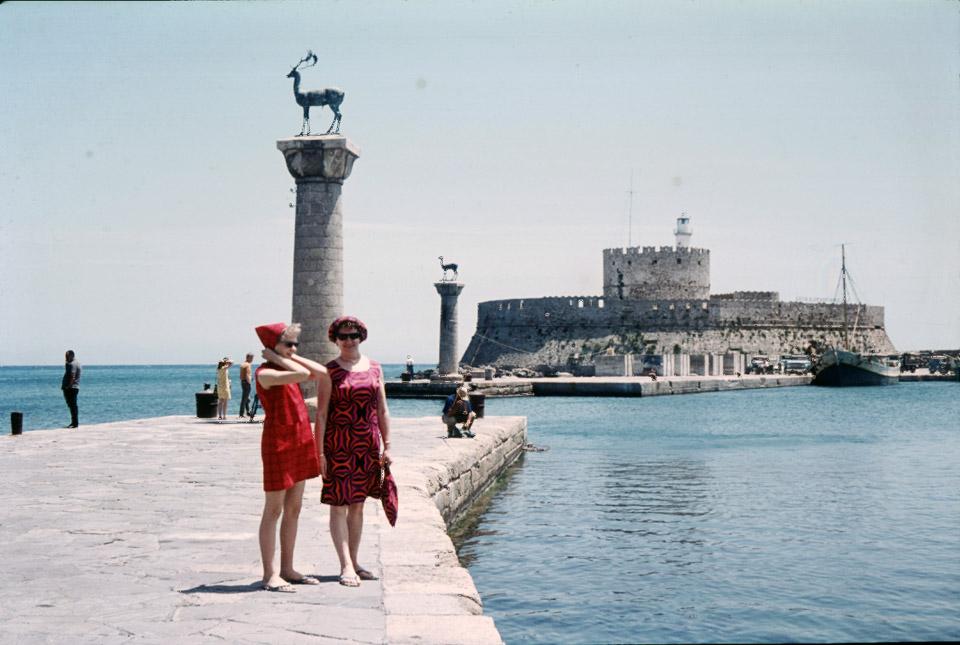
Erja and her mother in the Rhodes harbour. This is the photo which everybody who goes there will have. In 1969 we were on the way to Rhodes again, this time the Caravelle was OH-LSB “Tampere”. I drew a picture of it in my diary. It is rather short and the windows are not triangular, but otherwise it is almost recognizable: engines on the rear fuselage, the horizontal stabilizer is almost the right size and there are boundary fences on the wings.
Drawing of Super Caravelle from 1969. Some background information for the travel stories: my father was an air force mechanic during WW2, and he wanted his family to experience what it was like to fly. I was 6 years old when we travelled from Helsinki to Tampere on a Kar-Air DC-3. In 1962-69 and in the early 1970s I travelled somewhere with my parents every year, usually by air. And I thought flying was fantastic. |
|
Avainsanat: aviation history, restoration, Caravelle, OH-LEA, Sinilintu, Bluebird |
Restoration of the Ressu (Snoopy) experimental aircraft?s wing struts and building the missing oneLauantai 17.2.2024 - Tuesday Club member The restoration of the Ressu aircraft’s wing struts is completed. The aircraft was designed and built by the brothers Hietanen from Turku in the 1960s. Originally registered OH-HEA, the aircraft was registered as an experimental aircraft with the registration OH-XEA in 1969.
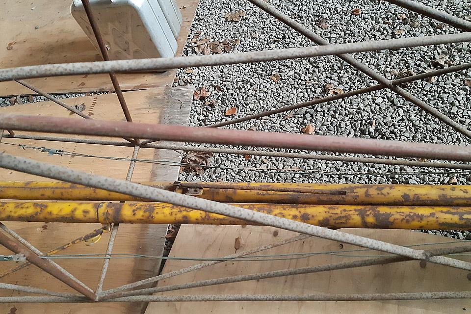
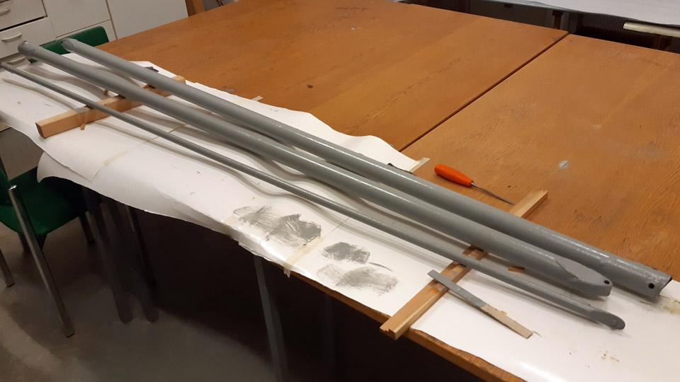
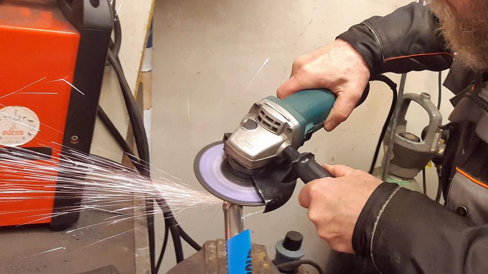
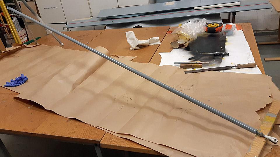
The wing halves of the high-wing Ressu are supported with two wing struts fastened to the fuselage lower edge. The front strut has been made of 50 mm and the rear strut of 20 mm thick steel tube. Both the front struts have remained, but only one of the rear struts. These three struts had been in storage inside the bare fuselage frame, which had no covering. The rusty struts were restored yellow according to the original paint scheme and the missing strut was built.
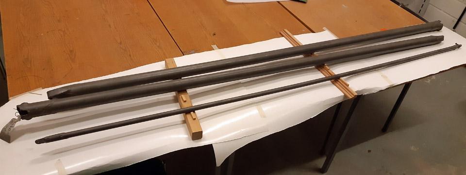
The restoration of the struts was started by taking them to be sand blasted at Taximo Oy in the Tattarisuo area in Helsinki. The sandblasted struts were dealt with a transparent anti-rust Isotrol-lacquer immediately after the sandblasting. The struts were primed with light grey Isotrol-paint of the shade RAL 7005. The light grey primer worked well for the yellow finishing paint of the struts.
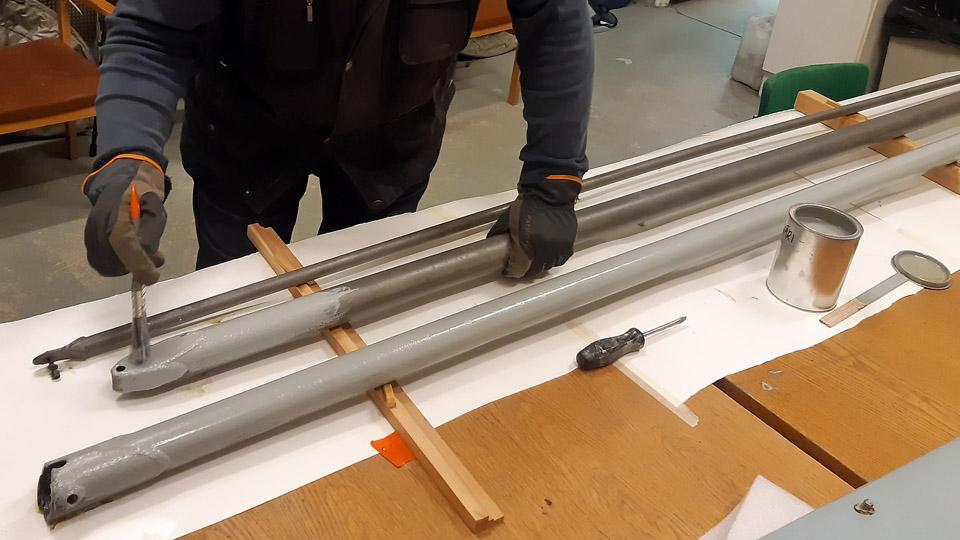
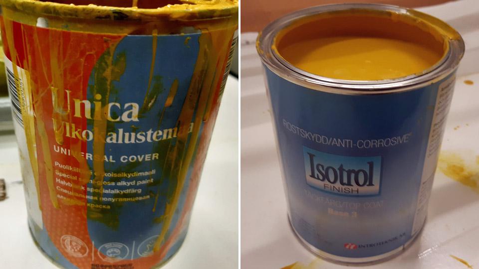
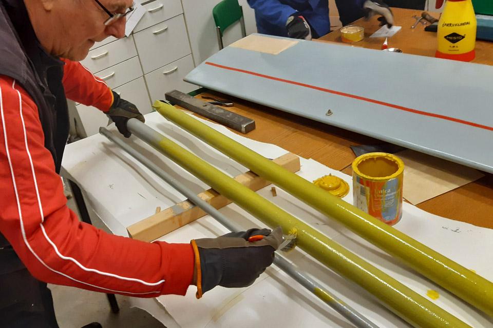
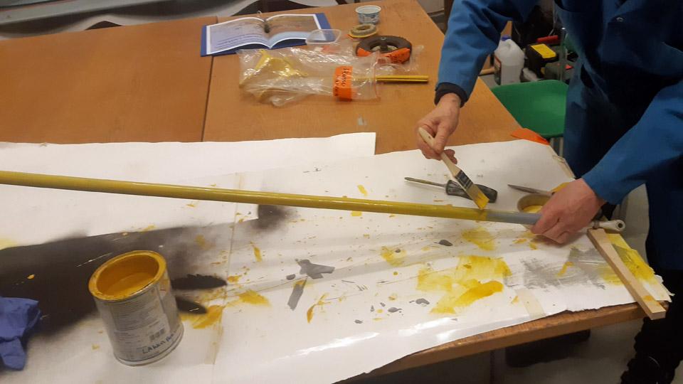
As the yellow finishing paint we used at first the Tikkurila UNICA outdoor furniture paint with RAL 1023 as the shade. The yellow paint had poor coverage, which we knew in advance. To replace the UNICA, a corresponding yellow Isotrol paint of the similar shade was chosen for the second coat of paint. The yellow pigment of the Isotrol paint has a better coverage, which was noted when painting the struts. They were painted with the yellow Isotrol three times over, so
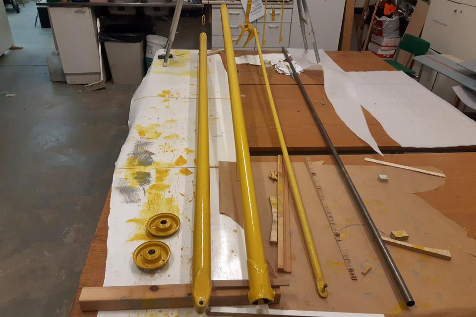
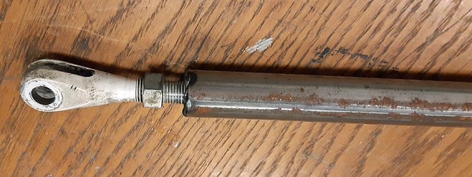
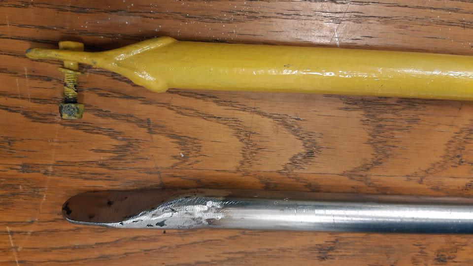
To make the missing rear strut, a 2,5 m long 22 mm thick steel tube was bought from Starkki hardware store. As a model for the building, a wing rear strut has survived. At both ends of the rear strut there’s a fixed bracket plate, with holes in it to fasten the strut to a bracket in the wing and the fuselage.
When we examined the photographs of Ressu at our disposal, we noticed that the lower end of the rear strut had been adjustable and not fixed, as was the case with the rear strut at our disposal. At the lower end of the strut can be seen a fork-like bracket with a threaded spindle. It was evident that the lower end of the rear strut had been changed to a fixed bracket. We decided to make the missing rear strut lower end adjustable, to correspond to the wing strut in the photograph. For this purpose we received a wing strut adjustable head used in a Super Cub.
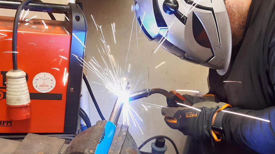
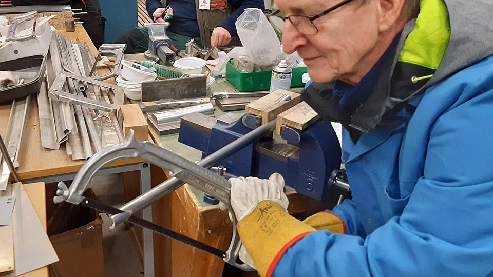
The building of the missing wing rear strut was started by cutting the steel tube to the measure of the rear strut. First we made the lower end of the rear strut. We welded a suitable nut, which fitted the threaded spindle of the lower end of the tube and screwed the bracket in place.
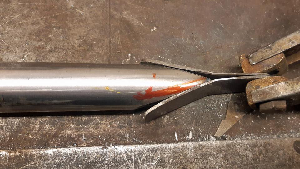
We made the wing rear strut top end a fixed one, according to the strut we had at our disposal. The end of the tube was sawn at an acute angle. After that the bracket halves for both sides were cut out of 2 mm metal plate to be welded in place. They were welded to the top sides of the tube. After welding, the bracket was ground to its final shape. When a hole had been drilled for the strut fastening bolt, the new strut was structurally finished.
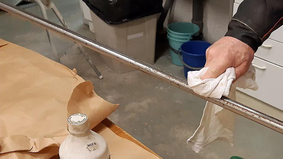
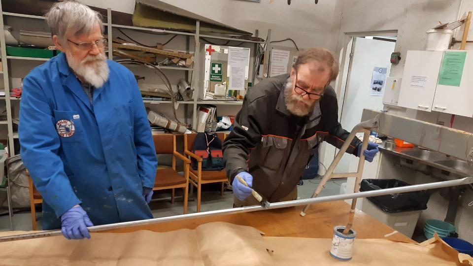
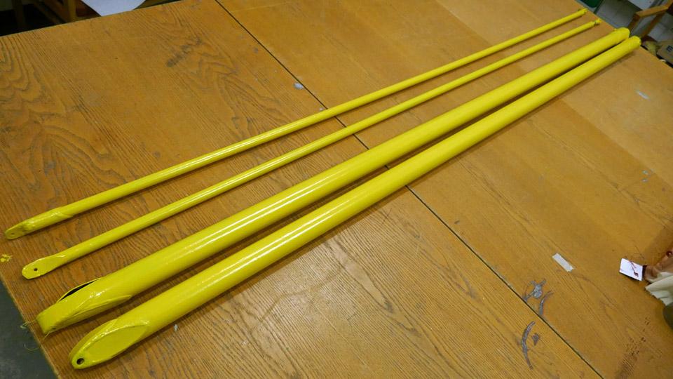
The new wing strut was primed with light grey Isotrol paint, the same way as the three original ones had earlier been dealt with. After the primer had dried it received a coat of yellow Isotrol paint. Thus we had restored the two original front wing struts and a rear strut of the Ressu-aircraft and built the missing wing rear strut Photos by Lassi Karivalo. Translation by Matti Liuskallio. |
|
Avainsanat: aviation history, restoration, Tuesday Club, Hietanen HEA-23b, OH-XEA, "Ressu" |
Ilmailumuseot.fi - Aviationmuseums.fi