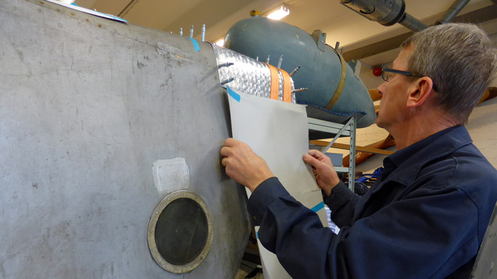
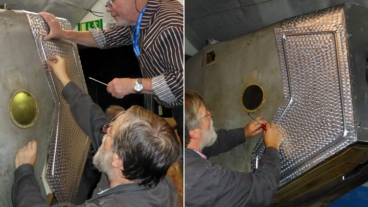
Side panels of Kurki engine mountingLauantai 21.10.2017 - Member of Tuesday Club When the frame of I.V.L.K.1 Kurki was brought in spring from Vesivehmaa to the Tuesday Club work space for renovation, it was in poor condition. After a year of hard work it is now nearly ready. One of the latest renovation phases was to build the openable side panels that were missing from the wooden engine mounting. The side panels are opened when maintenance work on the motor is done. The panel covering the upper part of the engine mounting was made already in spring.
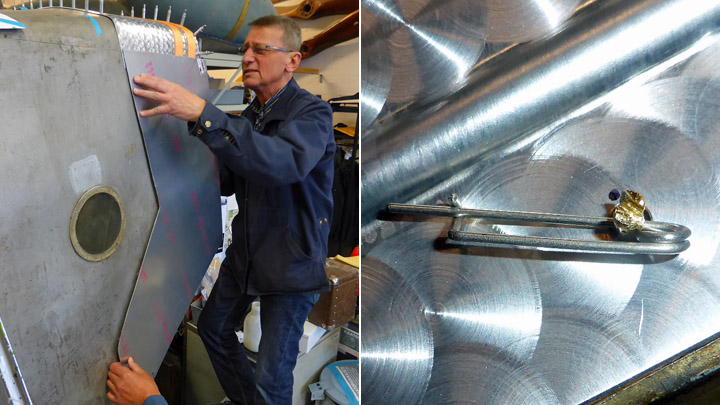
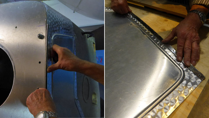
Old photographs of Kurki showed how the side panels of the plane had looked like. Cardboard models for the side panels were made based on old photographs and dimension measurements taken on the engine mounting. The rough shape of the side panel was then cut from 1,4 mm aluminium plate (quality class 6061). The rough cut was improved when placing the plate on the engine mounting. The side panels are locked on the mounting by their rear edge using Fokker-pins. When the panel shape was correct and matched the engine mounting dimensions, holes were drilled into the rear edge of the panel for the Fokker-pin locking bayonets.
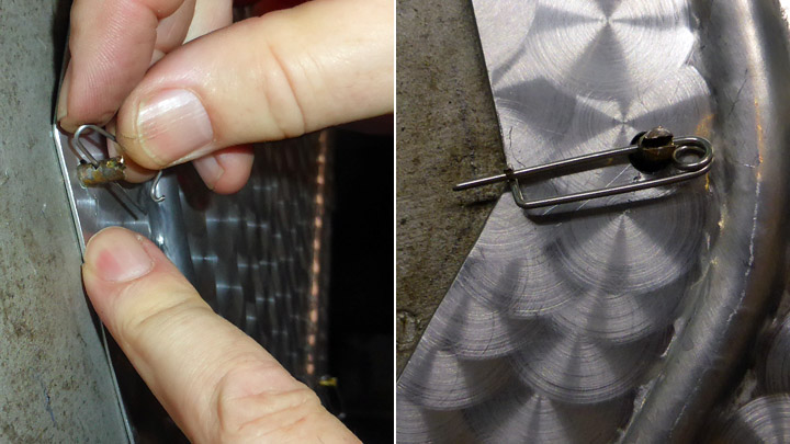
Five original locking bayonets were still left on both sides of the engine mounting frame, but the actual pins were missing. A few pins were available at the Finnish Airforce Museum but the rest of the pins had to be bent from steel wire. A couple of the brass locking bayonets had been damaged and had to be replaced by new ones made of brass screws of appropriate size. Some work was needed before the Fokker-needle bayonets found their way into the holes on the rear edge of the side panel.
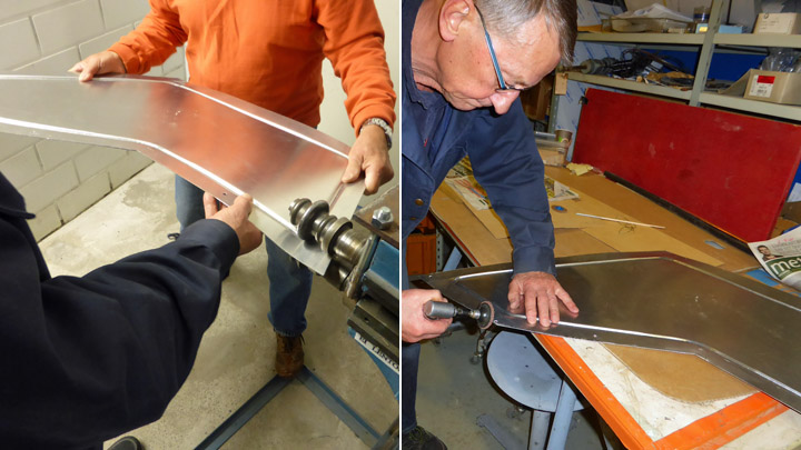
Based on old photographs the side panels had stiffening bends along the edges of the panel. Based on the photos, the knuckles were made at a distance of 5 cm from the edge of the panel. Some practice on the rotary machine was needed before appropriate knuckles were completed. However, making the stiffening knuckle caused the plate to stretch and bend a little and the plate had to be flattened and straightened. The straightening work was done using different methods and tools, such as a wooden hammer and tongs. Finally the panel fitted evenly onto the sides of the mounting.
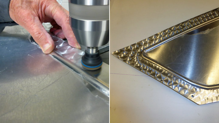
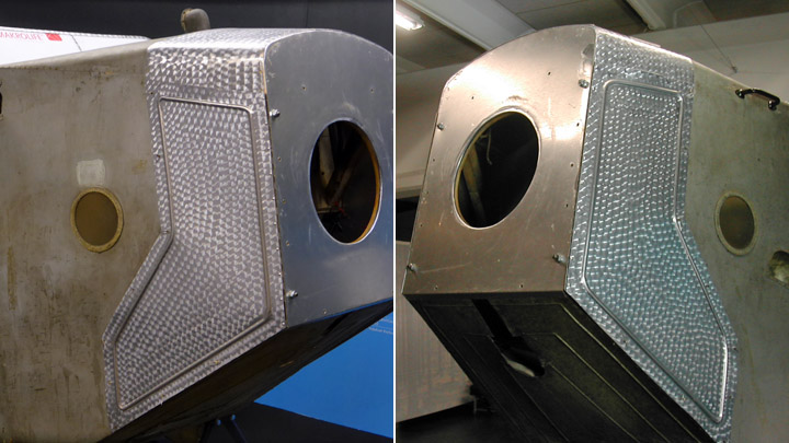
The engine mounting side panel surface has a circular grinding pattern, typical of the 1920’s. A similar grinding pattern had already been made on the upper panel in spring. The meaning of this pattern was originally mainly cosmetic. In the 1920’s the aluminium plate manufacturing process didn’t produce uniform quality and therefore the plating looked somewhat mottled. Applying circular grinding on the panel, the surface could be made look even and uniform in colour.
The circular grinding pattern was made using a nog plate installed on a pillar type drilling machine. The panel was moved forward under the nog plate half a pattern at a time. In the first phase the pattern was made on both panels on the area between the knuckle and the edge.
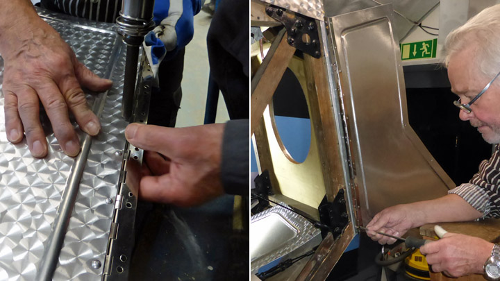
In the area inside the knuckle the pattern couldn’t be made before the panel fitted tightly on the engine mounting and the hinges were installed. The openable side panels are fixed on the engine mounting by their front edge using a piano hinge.
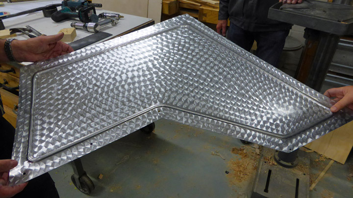
Some effort and shaping work was required before both of the side panels with their hinges were preliminarily fitted in their place. Now the circular grinding of the remaining areas could be done and the work to install the piano hinges could be started.
The piano hinges were cut to match the dimension of the engine mounting front edge and fitted onto the vertical wooden front edge. Also the places of the screws for the hinges were marked. Now the hinges could be riveted onto the front edges of the panels. The places of the rivets were marked on the front edge and holes were made for the rivets. 3 mm aluminium rivets were applied using a compressed air rivet gun. After the riveting the side panels were ready to be installed and brass screws were used when fixing the piano hinges onto the vertical wooden front edge of the engine mounting.
The side panels were now fixed to the mounting by their front edge and when they were closed against the mounting, all of the Fokker-pin bayonets didn’t fit into the holes on the rear edge of the panel.
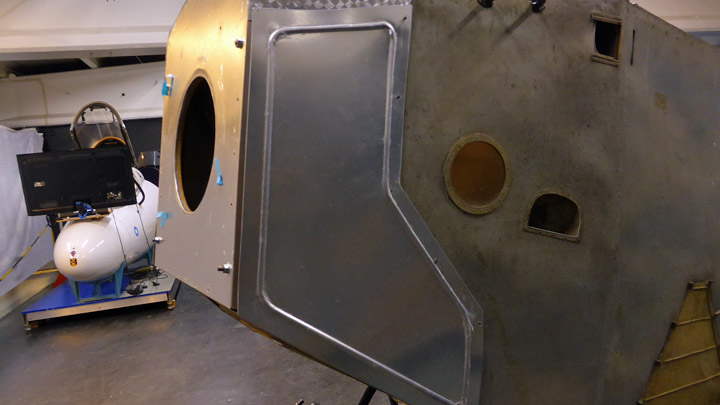
It could also be seen that the lower edges of the panels were slightly bulging. The panels had obviously been slightly bent when riveting the piano hinge. Therefore two additional locking bayonets had to be installed on the supporting wood on the lower edge and the corresponding additional bayonet holes had to be made on the panels. After this addition the side panels fitted tightly in their place against the engine mounting.
The work on the missing side panels was now completed. |
|
Avainsanat: aviation history, restoring, old aircraft, I.V.L. K.1 Kurki |
Ilmailumuseot.fi - Aviationmuseums.fi