Aluminium rib and oil cooler in left wing of MyrskyPerjantai 2.2.2018 - Member of Tuesday Club
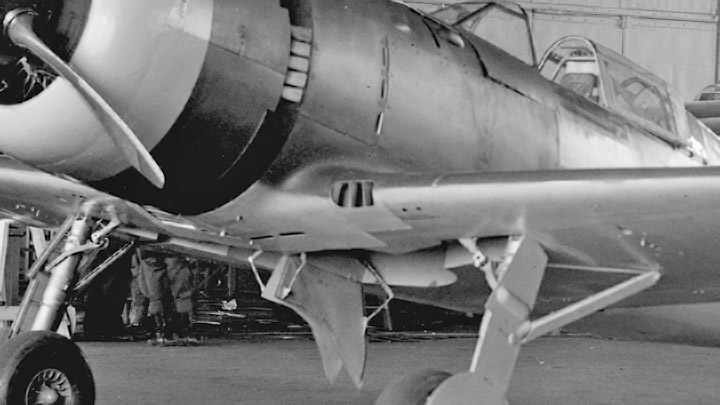
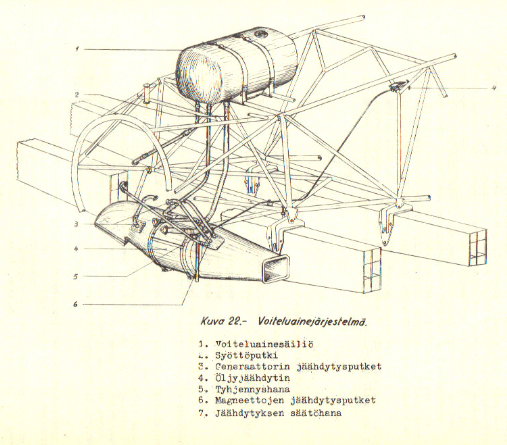
Photo: Photo archive of the Finnish Air Force Museum The oil cooler of the Pratt&Whitney R-1830 Twin Wasp engine in VL Myrsky is located in the lower part of the engine mounting, in front of the foremost wing spar. The cooling air is led in through a three-port air intake opening in the leading edge at the root of the left wing. The supply air flows from the air intake to the cooler in an air duct. From the other end of the cooler the warm exhaust air flows through an air duct to the exhaust opening which is located on the lower surface of the leading edge on the right wing.
At the root of the left wing the end of the air duct is attached to the leading edge rib which is made of aluminium plate. The other ribs of the leading edge are made of plywood. The aluminium rib has a hole with a flange matching the size of the air duct.
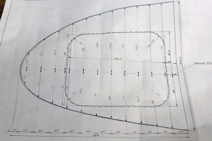
One of the tasks in the Myrsky restoration project was to build this aluminium rib. The drawings of the rib were available, so fortunately precise instructions for the task existed. First a mould had to be made in order to be able to bend the rib into its final shape.
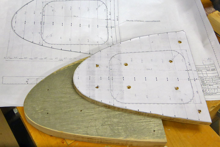
The profile of the rib was cut out from a paper copy of the drawing and glued on thick plywood. Tracing the edges of the drawing two similar rib-shaped plywood pieces were sawed. The mould was needed to bend the edges of the aluminium plate rib so that they form a rim 22 mm wide.
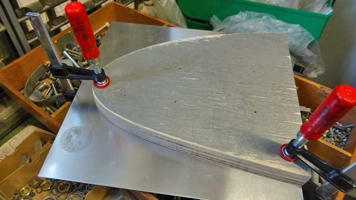
The plywood mould was used to draw the shape of the rib onto 1 mm aluminium plate and 22 mm was added around the shape for the rim. The preliminary shape of the rib was cut and attached tightly between the two plywood moulds.
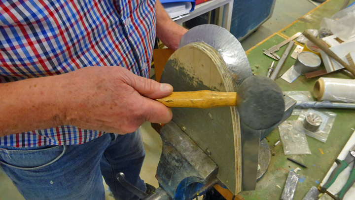
The following step was to bend the overlapping edge of the aluminium plate over the edge of the mould to make the rim. The plate was forced carefully to bend using a rubber hammer so that the aluminium wouldn’t break at the pleat / knuckle.
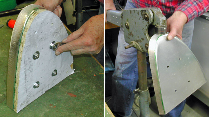
When the edge had been roughly bent, the rim was forced to its final shape using a sheet metal shrinker. The outer edges of the rib were now ready and the work could proceed to the next phase.
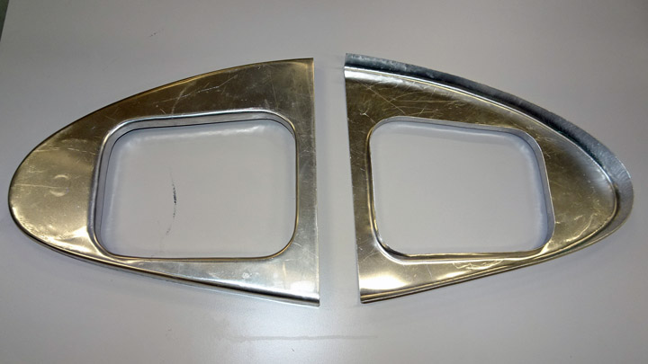
A hole for the air duct was made to the middle of the rib, following the dimensions in the drawing and taking into account the width of the flange for attaching the duct. The shape of the hole was drawn on the rib. The hole was made by first drilling a line of small holes following the drawn shape and then cutting along the holes using plate shears. The plywood mould of the rib was needed again: a similar hole was made in the middle of the mould. The aluminium rib was fixed tightly between the moulds. Then the edges of the hole in the aluminium plate were preliminarily bent against the edge of the plywood mould to form the flange and the final forcing was done using the sheet metal shrinker.
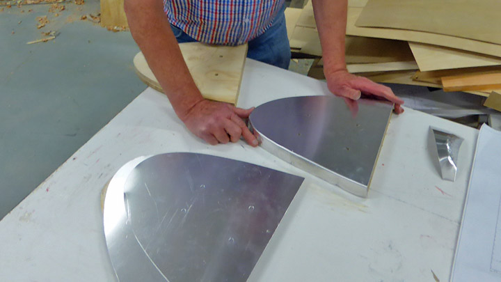
Now the rib for the leading edge at the root of the left wing was ready. Two similar ribs were made – one will be installed on the test wing and the other on the actual Myrsky wing. Photos: unless separately mentioned: Lassi Karivalo |
|
Avainsanat: aviation history, restoring, old aircraft, VL Myrsky II, MY-14 |
Ilmailumuseot.fi - Aviationmuseums.fi