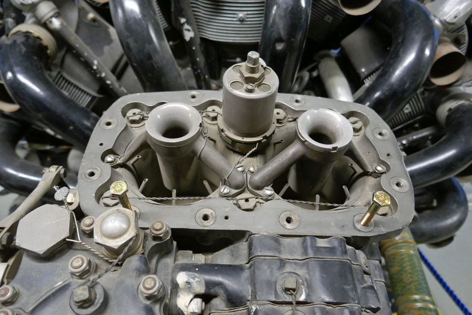
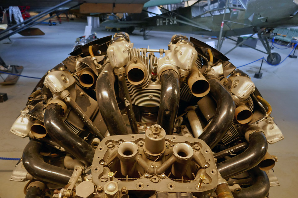
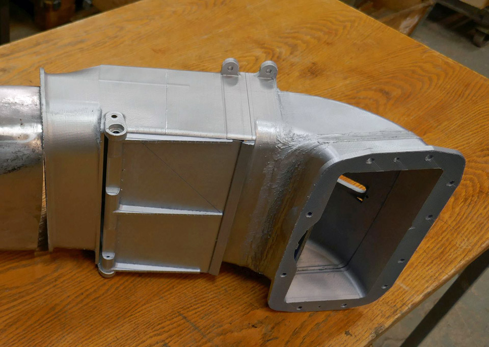
Myrsky engine's air horn and air intake are madePerjantai 28.5.2021 - Tuesday Club member The air flow entering an aircraft’s carburettor is controlled in the air horn, which is attached to the carburettor. When necessary, there is an air intake duct connected to the air horn. This is the case in the VL Myrsky II fighter, among others. In the Myrsky the two-sectioned air intake duct is connected to the air intake, located at the top of the NACA-ring, and is led between the upper cylinders to the air horn of the two-throat carburettor behind the radial engine. The suction air flow is controlled with the damper located in the air horn as well as the warm air flow, which comes through the engine space and protects the carburettor from freezing.
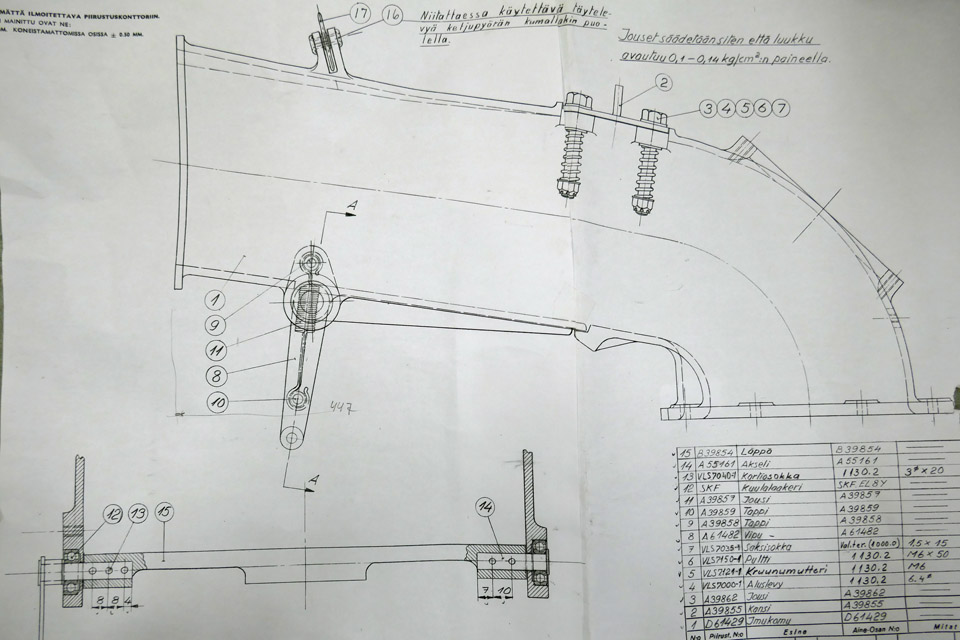
The Myrsky’s air horn is made of cast aluminium. The front piece of the two-section air intake duct, which is fastened on the NACA-ring, is made of aluminium plate. The tail section of the air intake duct is made of steel plate because it is located at a hot place between the cylinders. The tail section of the duct also connects the front section of the air intake duct to the air horn and is fastened to them with fastening clamps.
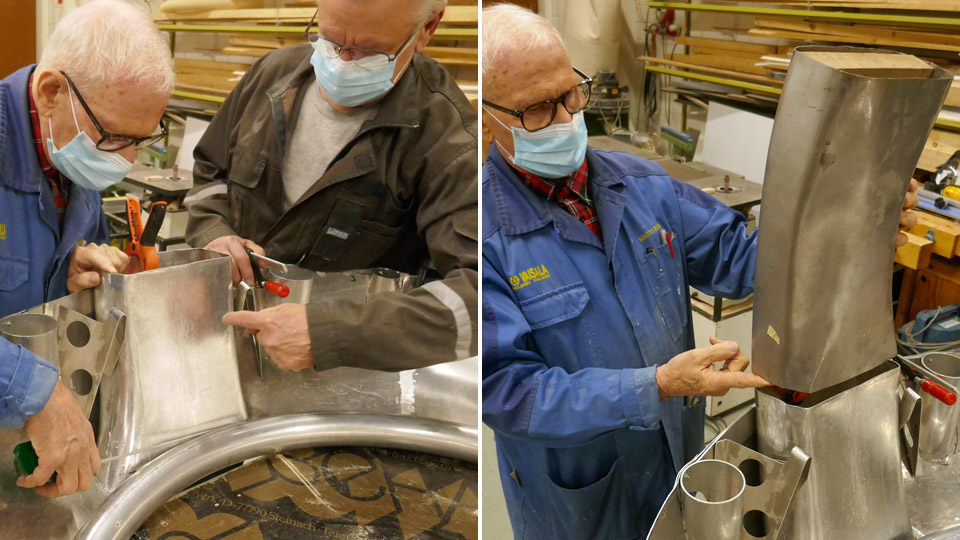
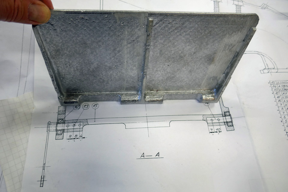
No original Myrsky engine’s air horn or parts of the air intake duct have been preserved and they had to be made in the restoration project of the MY-14. The sections of the air intake duct have already been made. The front section of the duct was made according to the drawing from 1,0 mm thick aluminium plate, using a mould. The tail section was made from 1,0 mm thick steel plate. The sections of the air intake duct have been fitted into place and the front section of the duct is being fastened to the opening in the NACA-ring.
The SASKY Municipal Education and Training Consortium at Sastamala helped to manufacture the air horn from cast aluminium. They were interested in the ongoing Myrsky restoration project and asked if there was some restoration work which could be made as 3d-printing by the SASKY students. The Tuesday Club team suggested that they could make the rather difficult air horn - and they accepted the challenge.
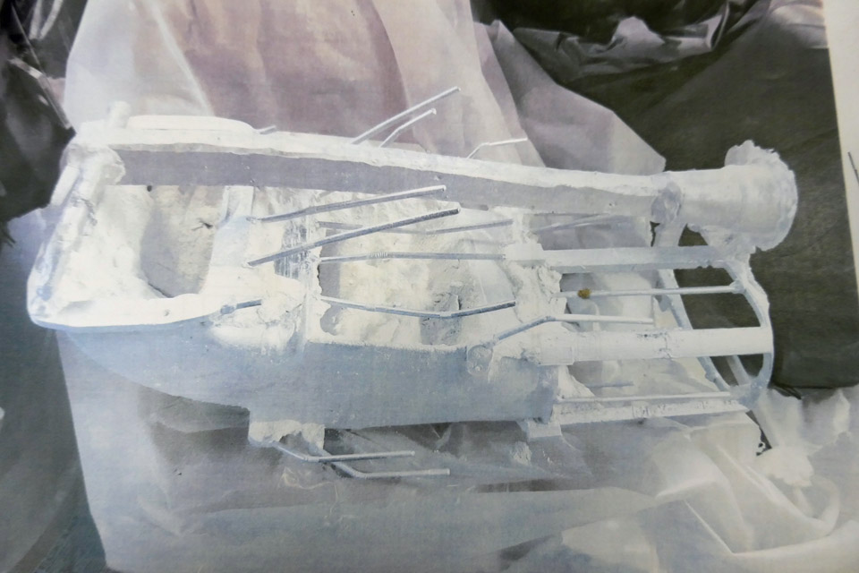
Photo: SASKY
The project was started at SASKY by 3d-printing a plastic 1:1 scale model of the Myrsky’s air horn according to the drawings. Then the actual cast mould for the aluminium cast was made based on the 3d-print. The 3d-printed model was dipped several times in a ceramic solution and a ceramic layer was formed, layer by layer, on the plastic model. Flow channels and air extract were also made on the cast mould. Then the plastic 3d-model was melted from inside the ceramic shell, and the cast mould for the air horn was ready. The liquid AlSi 12 aluminium was poured into the mould. When the aluminium had cooled the mould was broken and the flow channels were removed, and the surface was ground smooth.
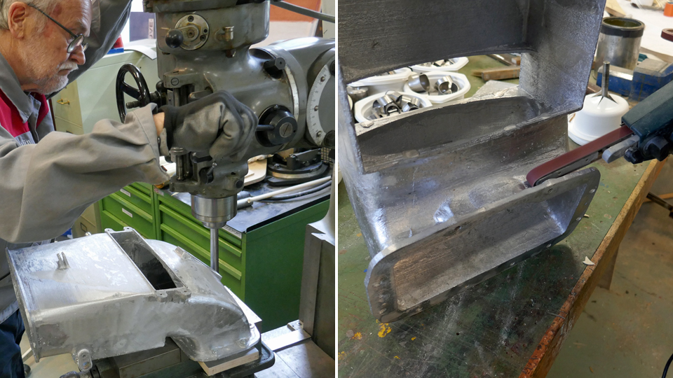
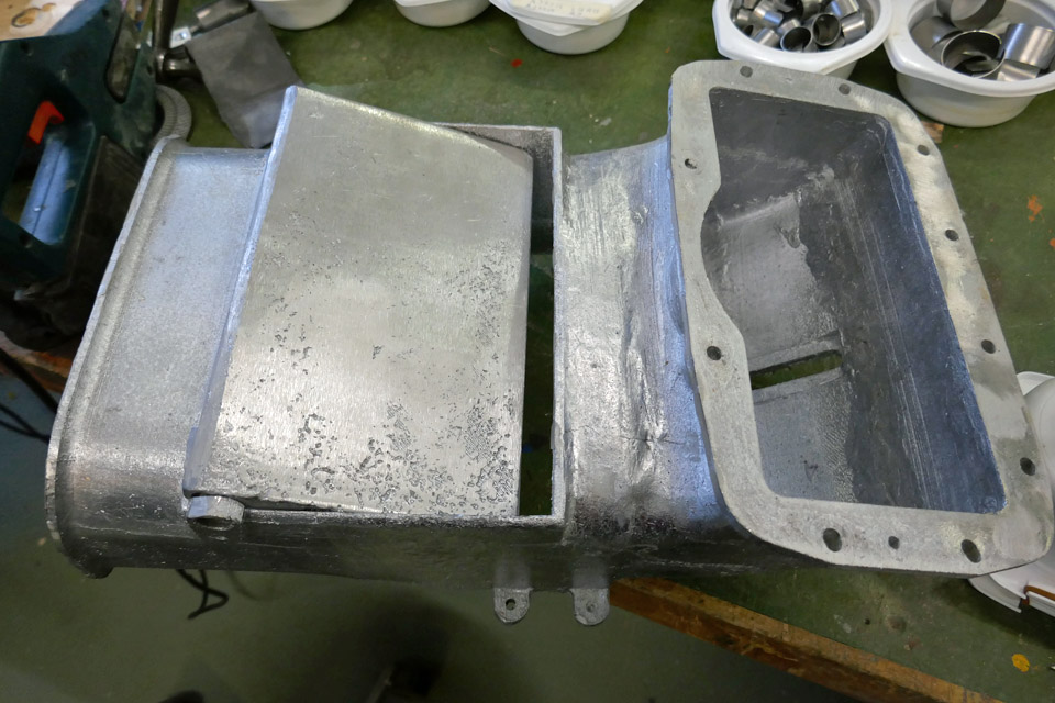
The cast aluminium air horn is now at the Tuesday Club and is ready for further work. Some extra material has been ground off. Holes for fastening bolts will be drilled. The Tuesday Club wishes to thank the SASKY Municipal Education and Training Consortium for preparing the aluminium cast of the air for the restoration the restoration project of the VL Myrsky II (MY-14). Photos: Lassi Karivalo except if otherwise mentioned. Translation: Erja Reinikainen. |
|
Avainsanat: aviation history, restoration, VL Myrsky II, MY-14 |
Ilmailumuseot.fi - Aviationmuseums.fi