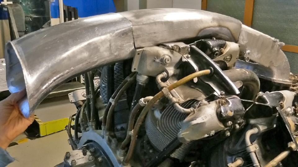
Works on Myrsky carburettor air intake and NACA-ringTiistai 22.6.2021 - Tuesday Club member The half-finished air horn and air intake ducts have been preliminarily assembled on the VL Myrsky II which is under restoration. The Myrsky had a Pratt &Whitney R-1830 radial engine and a similar engine is available at the Finnish Aviation Museum. Fortunately it has been possible to test the assembly at the museum and there is no need to travel to the Air Force Museum at Tikkakoski, where a similar engine has already been installed on the Myrsky’s (MY-14) fuselage.
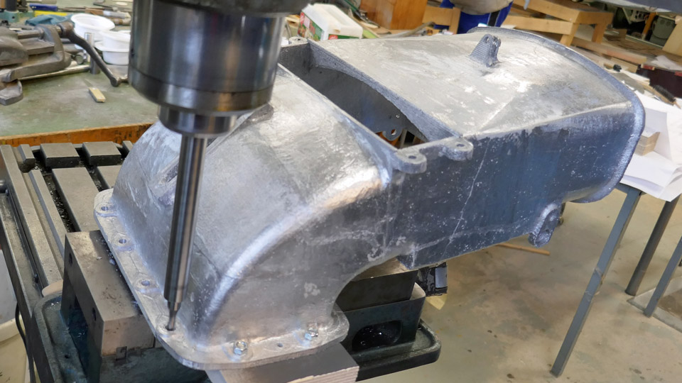
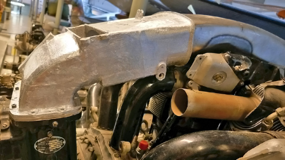
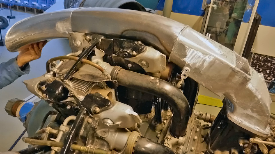
Holes for the fastening bolts were drilled on the cast aluminium air horn and the air horn was fastened with a couple of bolts onto the carburettor of the engine, located in the museum hall. It fitted nicely into its place. Then the two air duct sections could be assembled into place between the air horn and the NACA-ring.
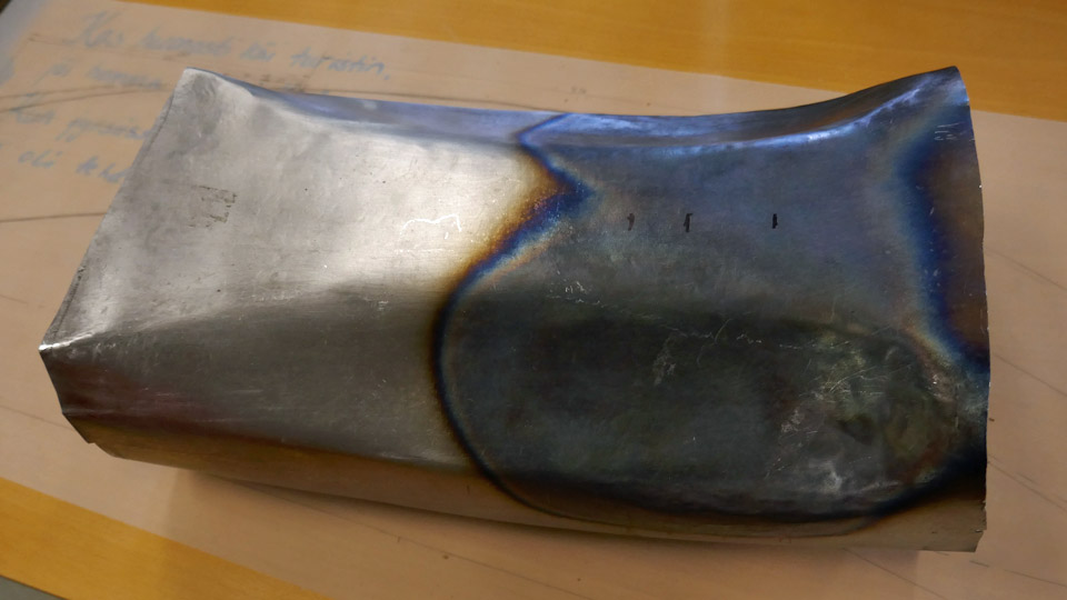
The Tuesday Club team noticed that the section of the air duct, made of steel plate because of its location above the hot engine, did not fit properly. The reducers made on its lower part were too shallow and the air intake duct couldn’t be pressed sufficiently deep between the cylinder head covers. The air intake duct was heated using a welding flame and shaped to fit better. Then the two air intake duct sections were assembled above the engine and fastened on the air horn. Even when half-finished it is a great sight!
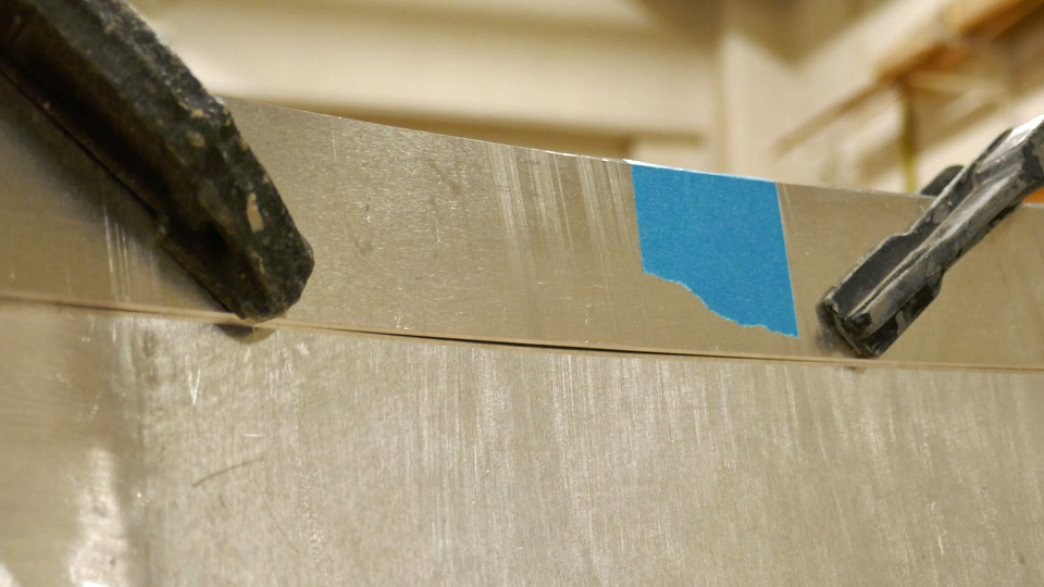
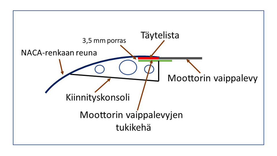
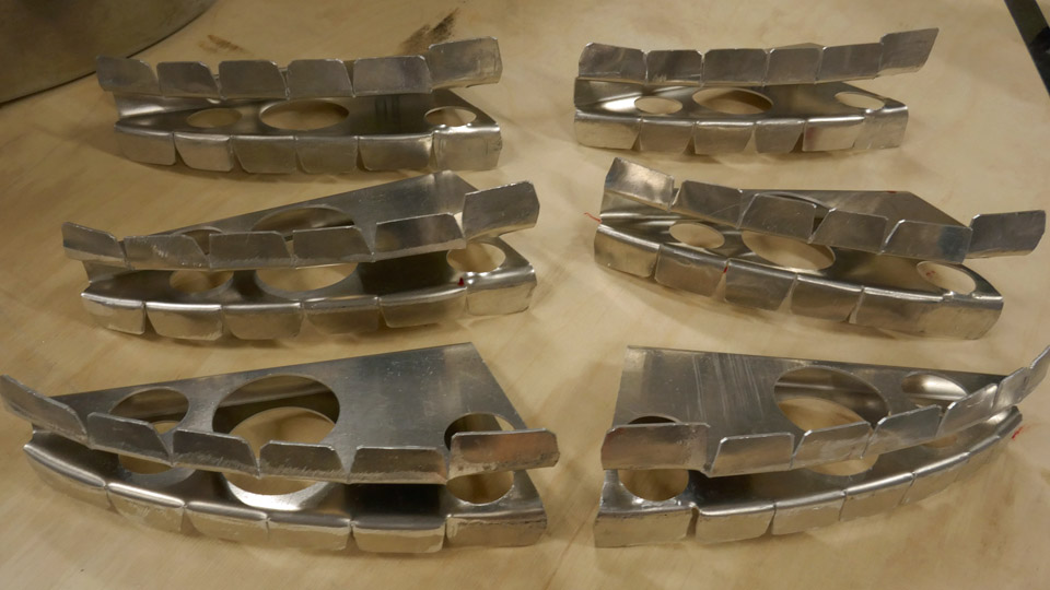
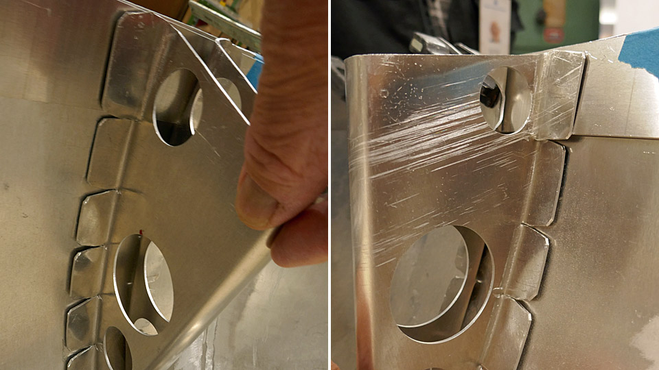
The consoles of the NACA-ring, which are needed to fasten the ring on the brackets on the cylinder heads, had to be modified before riveting on the edge of the NACA-ring. Especially the console hems have needed shaping. The console is riveted on the NACA-ring by its hem. The hem has to meet the curved shape of the NACA-ring and to take into account the filler batten, which is a 2,5 mm aluminium batten riveted on the edge of the NACA-ring, and the 1,0 mm aluminium supporting frame of the engine fairings. The supporting frame is 75 mm wide, and it is riveted on top of the filler batten so that it extends 32 mm outside the edge of the NACA-ring. It forms a shoulder on which the edge of the detachable engine fairing rests and meets the edge of the NACA-ring in a butt joint. There is a very general overview picture of this structure attached.
Translation: NACA-renkaan reuna = Edge of NACA-ring, 3,5 mm porrastus = 3.5 mm offset, Kiinnityskonsoli = Console, Moottorin vaippalevyjen tukikehä = Supporting frame of detachable engine fairing rests, Täytelista = Filler batten, Moottorin vaippalevy = Detachable engine fairing rests.
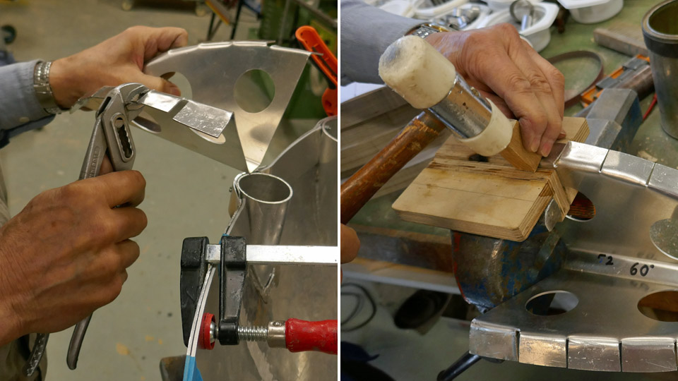
The hems of the NACA-ring consoles were shaped using pliers and a plastic-headed hammer and a piece of wood. A 3,5 mm offset was made on the upper end of the console for the filler batten and the supporting frame. All console hems have now been shaped and are ready to be riveted into place. Before that can be done, the filler batten and the supporting frame on top of it will have to be riveted onto the edge of the NACA-ring. The supporting frame is made of four sections and the sections are ready to be installed.
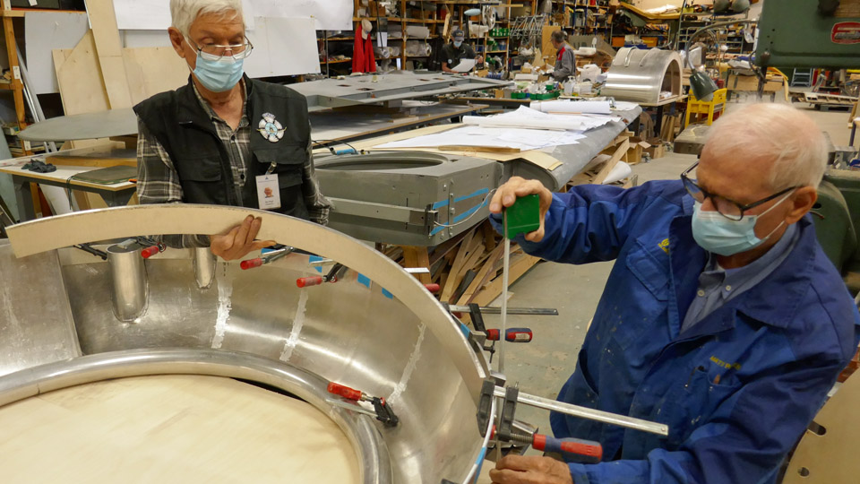
Up to now the filler batten has been fastened on the upper edge of the NACA-ring with clamps. Now it is debated how the riveting of the filler batten and the supporting frame on the NACA-ring edge will be done so that the filler batten settles exactly to the same level as the NACA-ring’s edge. Photos: Lassi Karivalo. Translation: Erja Reinikainen. |
|
Avainsanat: aviation history, restoration, VL Myrsky II, MY-14 |
Ilmailumuseot.fi - Aviationmuseums.fi