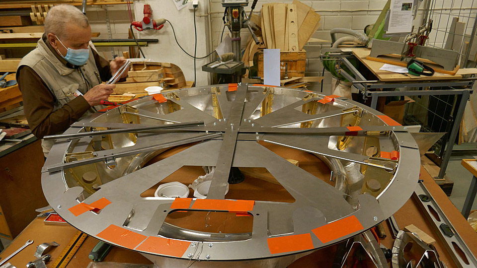
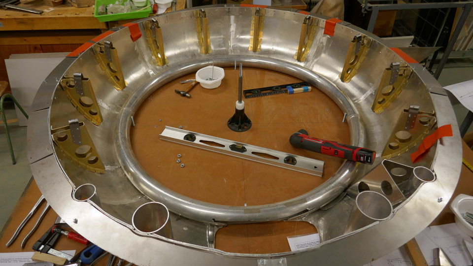
The fitting of Myrsky's NACA-ring bracket formers and brackets for rivetingTiistai 19.7.2022 - Tuesday Club member In the restoration of VL Myrsky II the construction of the engine cowling or NACA ring front part, which is demanding, has been under work already for a couple of years. The Myrsky engine cowling consists of the engine covering NACA ring’s solid front and rear parts and the openable engine cowlings between them. This blog deals with the installing of the bracket formers to be riveted to the solid front part of the NACA ring. Later in this blog the solid front part of the NACA ring will be called NACA ring for simplicity. The Myrsky’s NACA ring has proved to be very difficult to make, and we have not managed to avoid extra work. This was caused by amongst other things the uncovering of the lost Myrsky major series NACA ring drawings at the end of last year. They differ especially in the upper part from the initial series Myrsky’s NACA ring drawings, according to which we have been building the MY-14 NACA ring. The difference between the drawings was, that in the major series NACA ring the diameter of the upper part of the ring is larger than that of the initial series. Because of this, the NACA ring that we had built had to have its upper part diameter increased, so that it would correspond to the shape of the major series shape of MY-14. The enlargement was possible by forging the upper part of the aluminium ring to the measurements of the major series. There are 14 bracket formers in the NACA ring altogether. Of those, ten are situated in the part of the NACA ring, which equates the rotation block. Four bracket formers are situated aside from the rotation block in the expanding upper part of the NACA ring. The opening of the air horn and the flame tubes of the four machine guns are situated in this area.
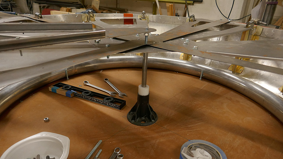
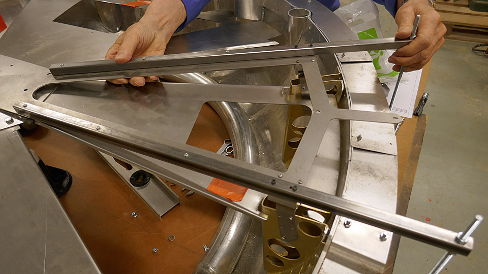
At the same time a jig was made out of a steel plate, to assist in focusing the bracket formers to their places. With the aid of a set up jig, which was made out of steel plates and locked in the “central hub” of the assembly table, two bracket formers can be positioned into place. After that the jig is moved forward to position and install the next bracket formers. The positioned bracket formers were fastened to the NACA ring with a couple of small bolts. The final fastening will be done by riveting.
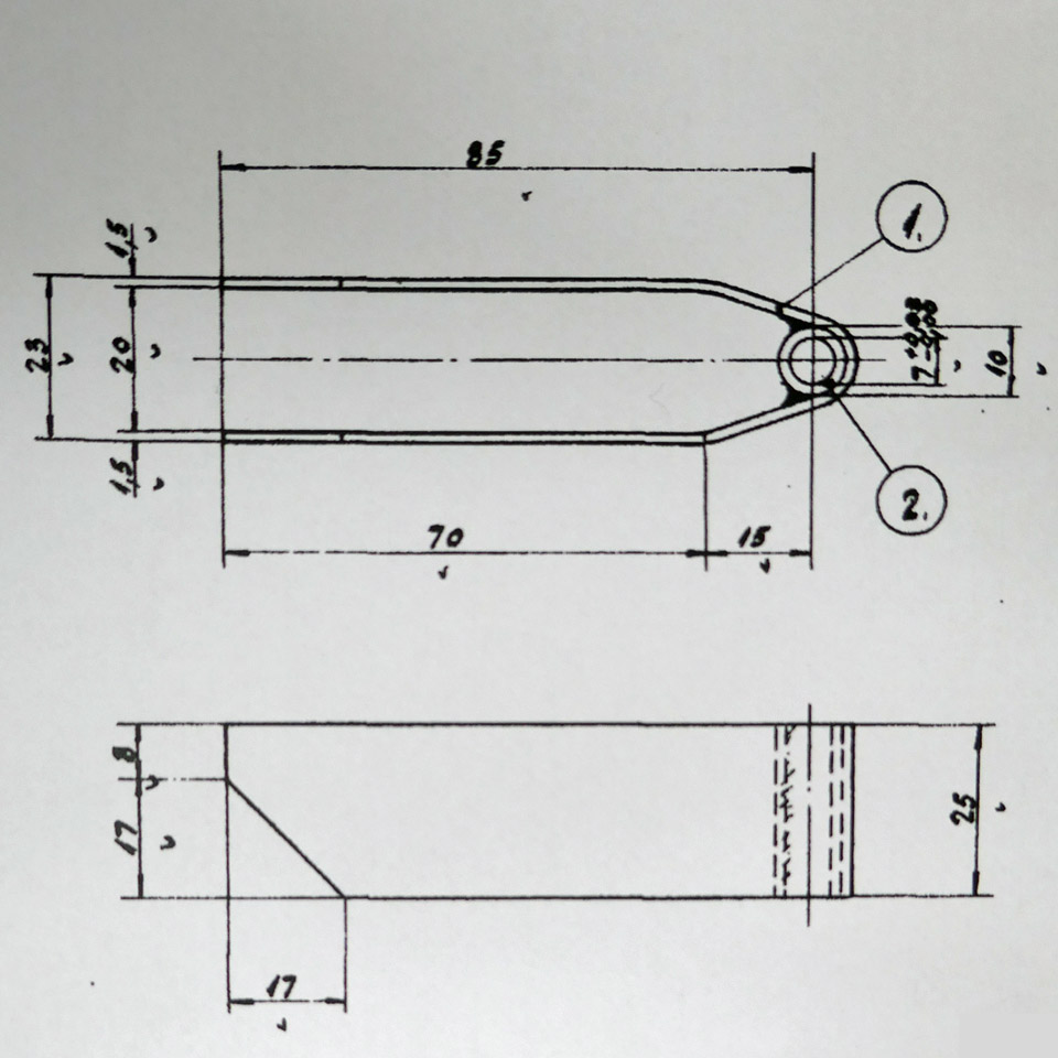
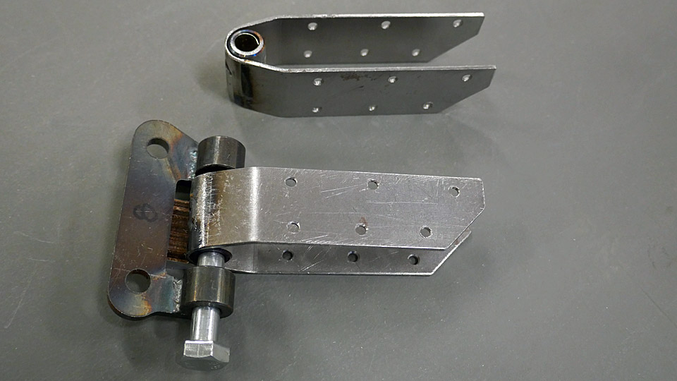
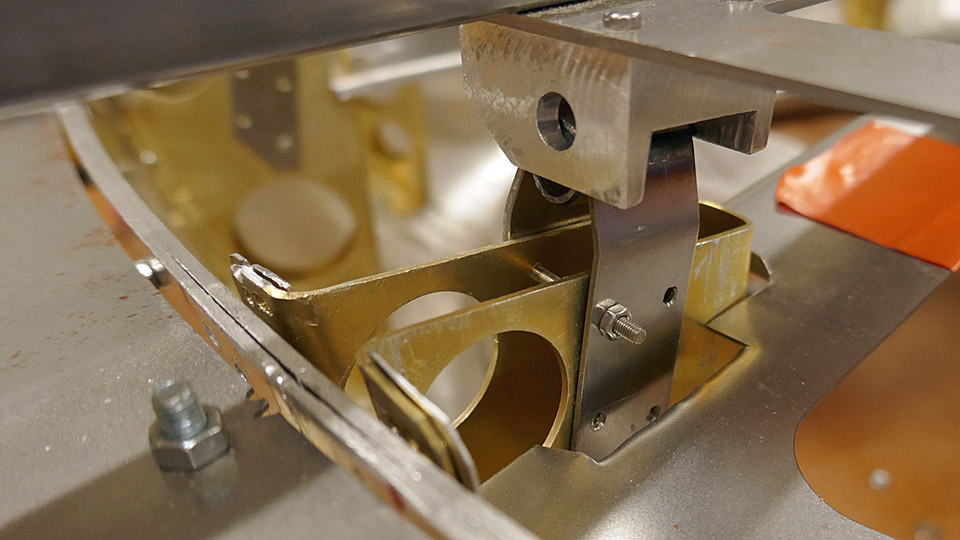
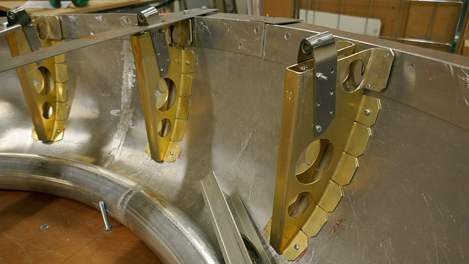
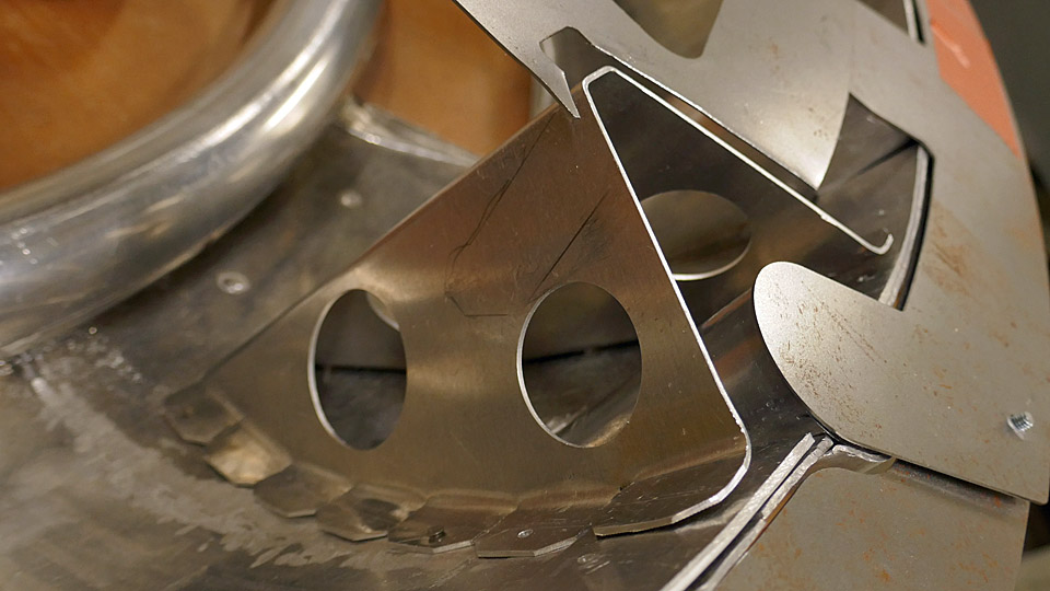
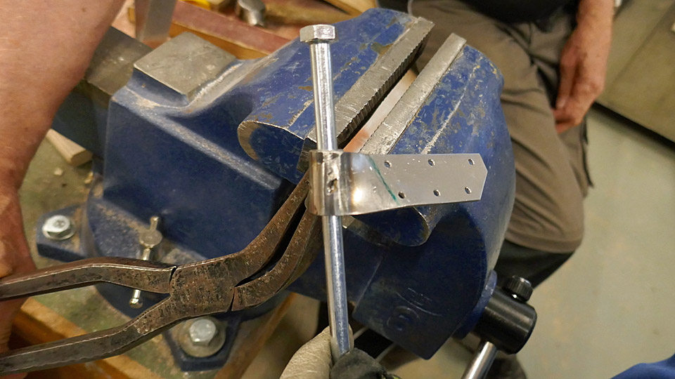
When the chromated 10 bracket formers had been installed, the actual brackets were installed at their tips, with which the NACA ring is locked with connection pieces to the eyes of the valve housing of the engine. The bracket on the former is a prong-like piece, bent from 1 mm steel plate, which has a welded socket for the fastening bolt at the end.
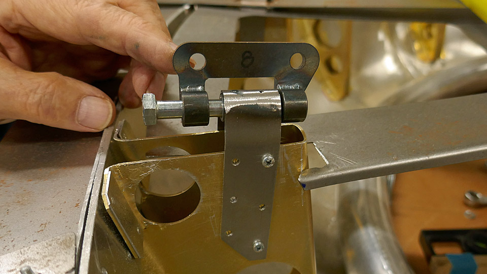
The brackets are installed at the end of the formers at an angle of 7.5 degrees. So they will meet the valve housing eyes to fasten the NACA ring to the engine. The brackets of the formers and the eyes of the valve housing are locked to each other with connecting pieces. The connecting pieces are fastened with bolts to sockets at the end of the former and with two bolts to the holes of the eyes in the valve housing.
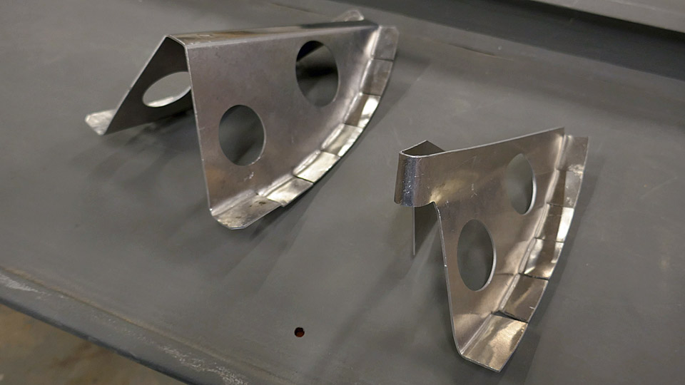
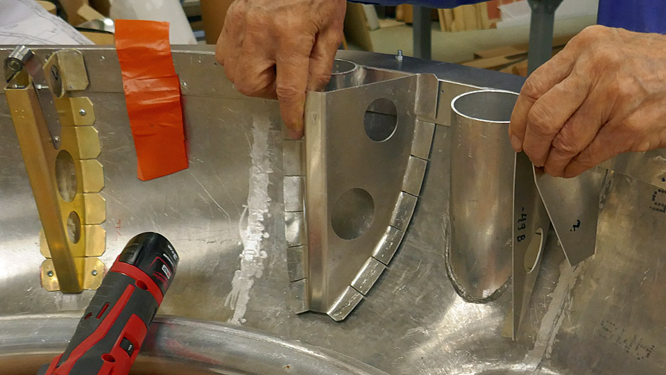
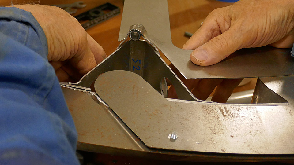
When all ten chromated bracket formers with their brackets had been installed in place, the shaping work of the four bracket formers and their brackets to be installed on the upper part of the NACA ring was started. The bracket formers by the outer flame tubes are distinctly shaped more open-angled, compared with the other V-shaped bracket formers, to enable the flame tubes inside them. The bracket formers that are fixed on either side of the air horn differ from the other bracket formers in shape. In a way they are only half-sized compared with the other V-shaped formers.
First the open-angled bracket formers at the flame tubes were shaped to be installed. They were fastened tentatively in place with the aid of a jig, made especially for these two brackets. After this the shaping of the prongs, attached at the end of the bracket formers with sockets, so that they could be shaped into the form of more open bracket formers. The position of these brackets differs from the other bracket formers so that the bracket is right at the top of the bracket former. The installing of the bracket formers of the NACA ring upper part are still under work. Photos: Lassi Karivalo Translation: Matti Liuskallio. |
|
Avainsanat: aviation history, restoration, Tuesday Club, MY-14, VL Myrsky |
Ilmailumuseot.fi - Aviationmuseums.fi