Assembling the Myrsky wing root fairings and the oil coolerMaanantai 15.7.2024 - Tuesday Club member Apart from the Myrsky-project other activities of the Tuesday Club are on hold for the summer break. So the parts of the OH-XEA “Ressu”, Caudron C.59 (CA-50), Valmet Tuuli III (TL-1) and the Link Trainer, heaped in the former Aviation Museum coffee room, can wait for the work to continue halfway through August, when the autumn season 2024 for the Tuesday Club will commence.
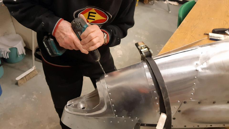
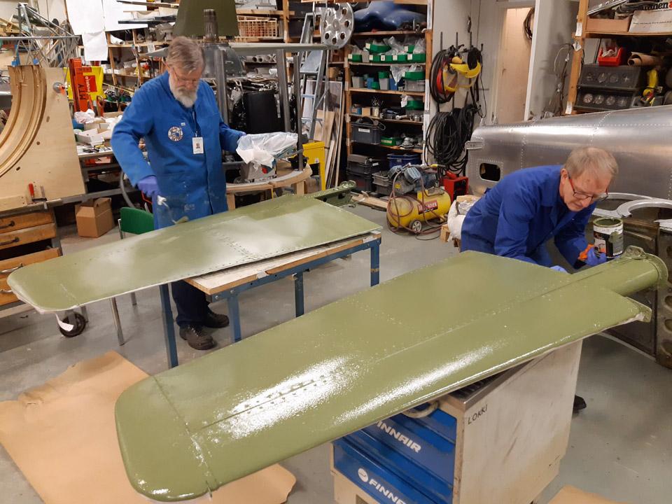
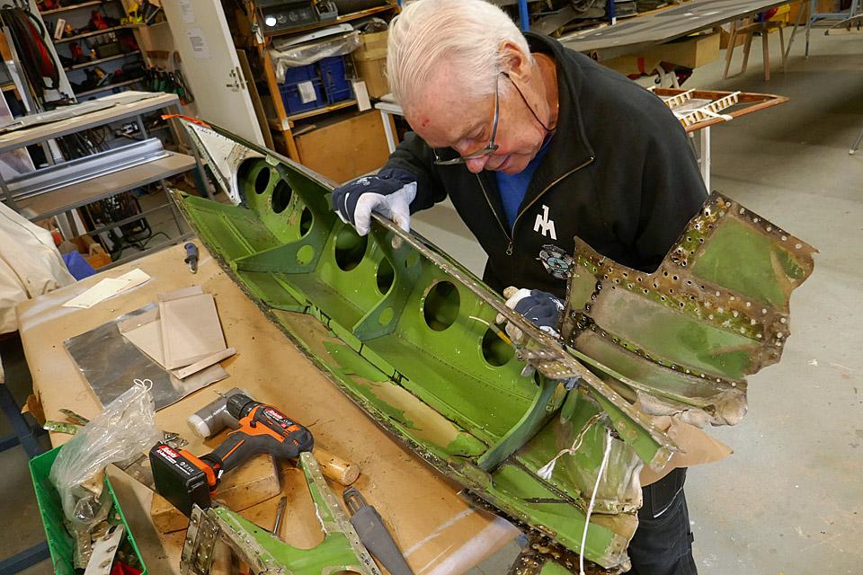
The project members of the Myrsky restoration team at the Tuesday Club have toiled “day in and day out” to finish and assemble the wing root fairings covering the wing/fuselage seam and the oil cooler, with its intake and exhaust air horns. Both these projects have taken more time than planned, so the Myrsky II (MY-14) roll-out, planned for the beginning of August, will be delayed. The summer holiday season both at the Finnish Air Force Museum and at Patria industries have affected in the delay.
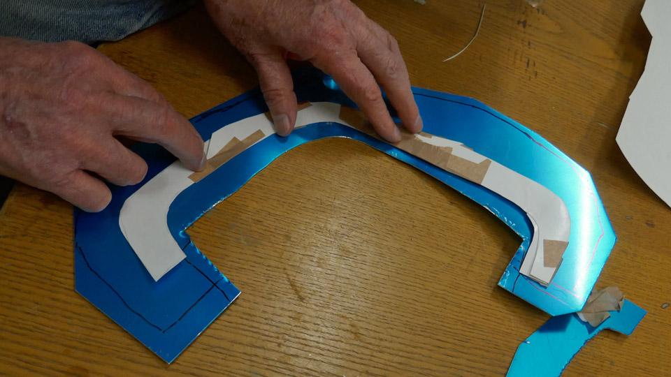
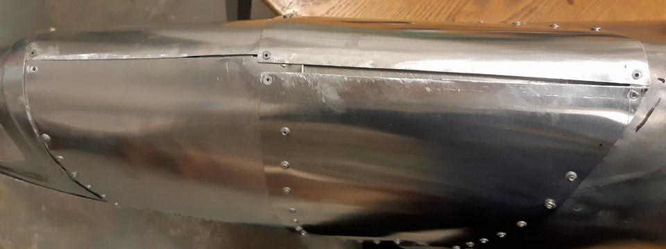
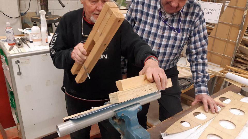
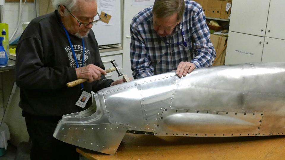
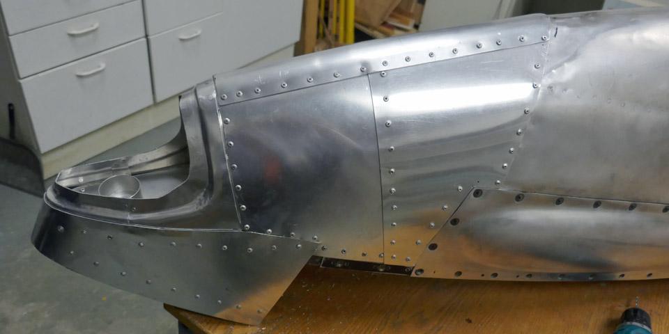
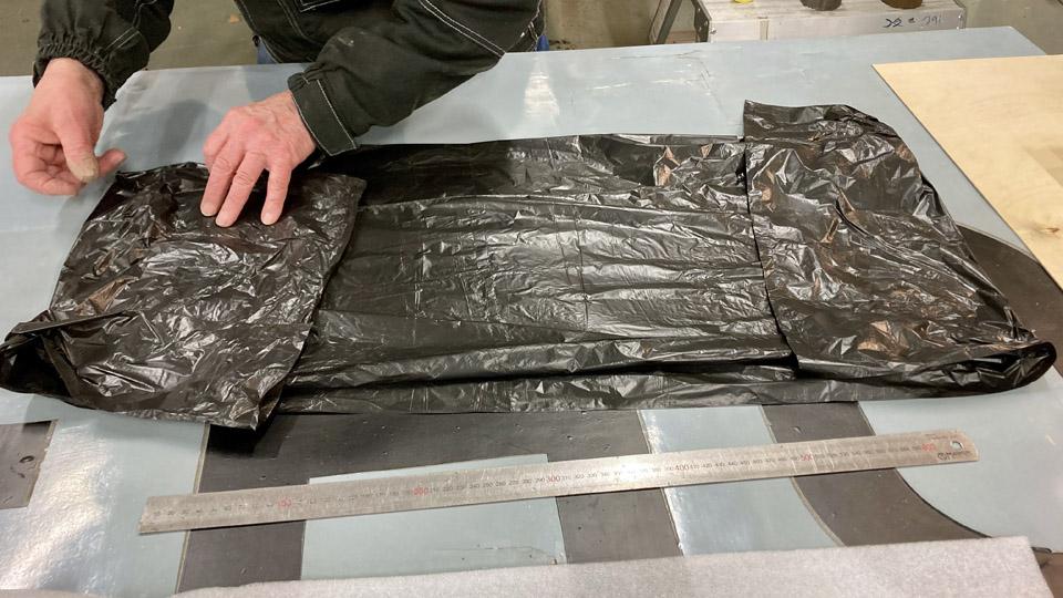
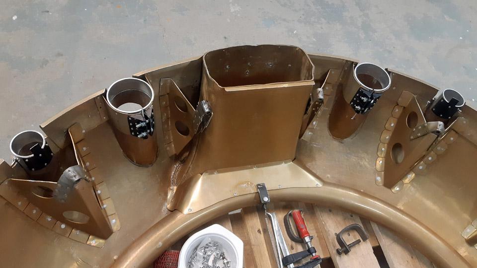
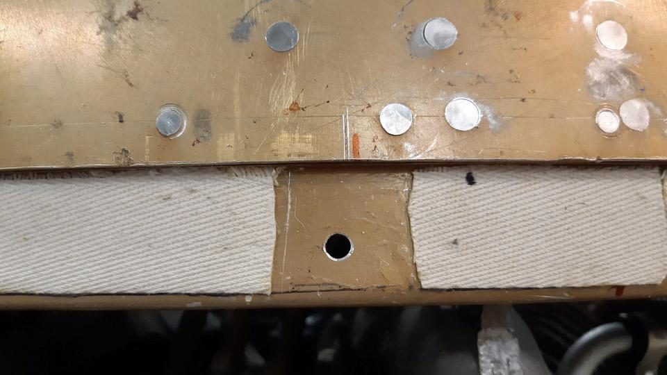
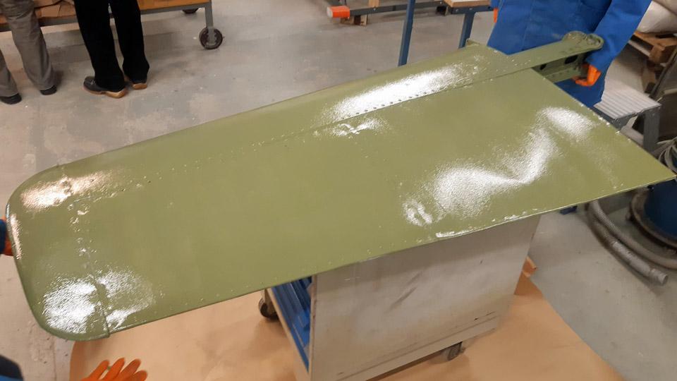
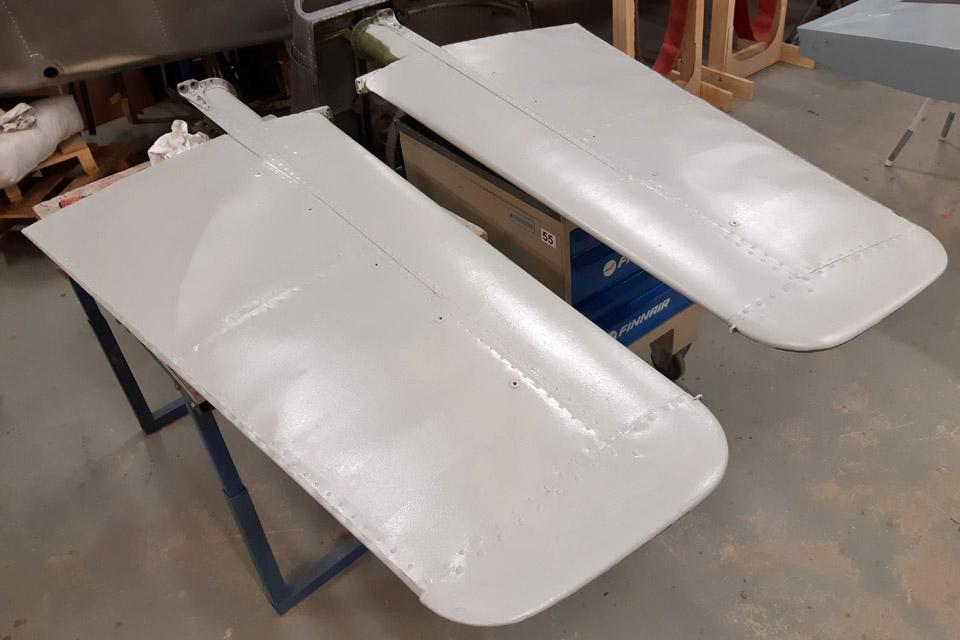
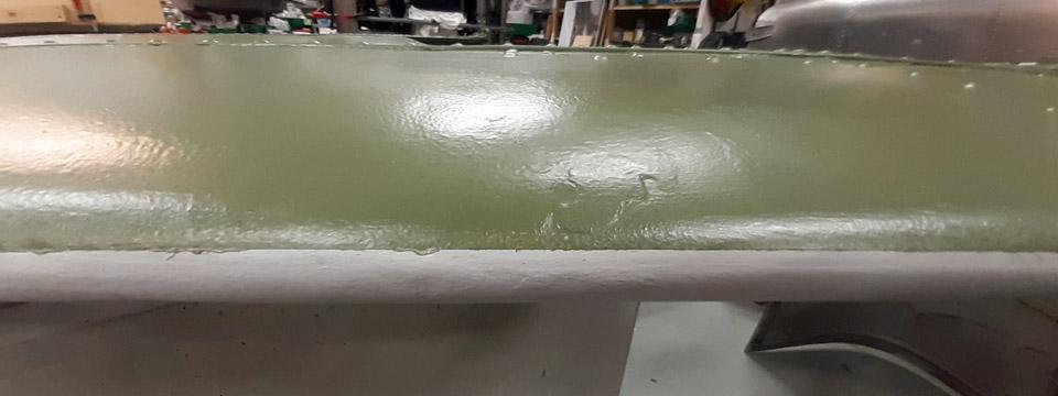
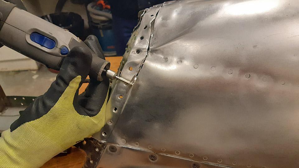
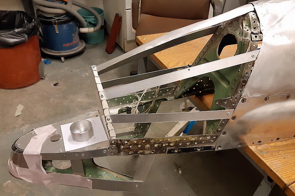
Oval-shaped openings and a flapped hatch were made to the lower surface of both the right and left-hand side wing root fairings. The narrow oval openings are for cooling the wing root fairings, which for their part cool down the engine oil cooler, sheltered by the fairings. The edges of the openings cut to the aluminium plate were strengthened with a 1 mm thick aluminium strip. The strips were fastened with rivets.
The wing root fairing edges were likewise strengthened with aluminium strips on both fairings. That way the fairings stay better in form and are easier to handle when they are more rigid. The strips were riveted to the wing root fairings with countersunk rivets.
Photo by Heikki Kaakinen
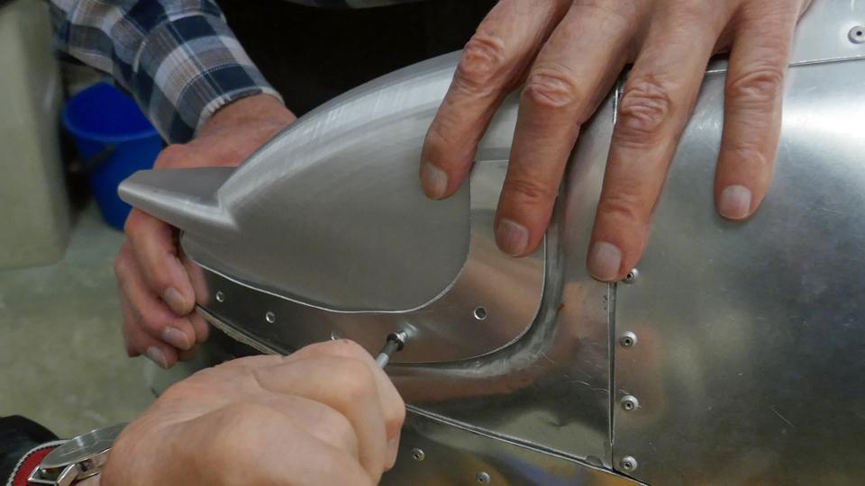
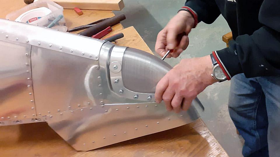
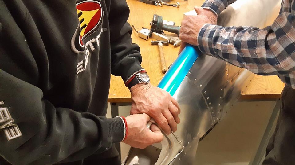
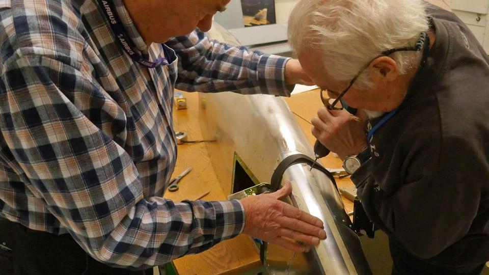
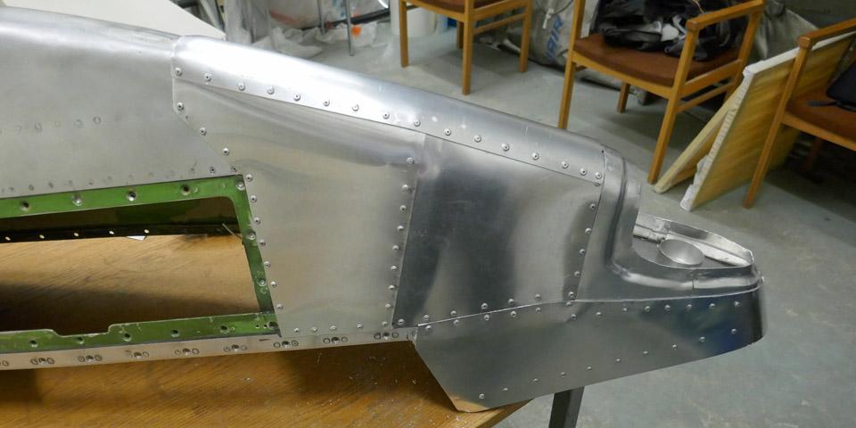
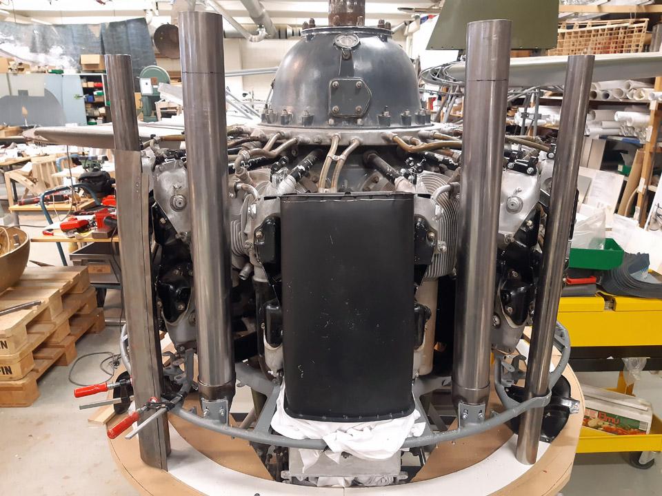
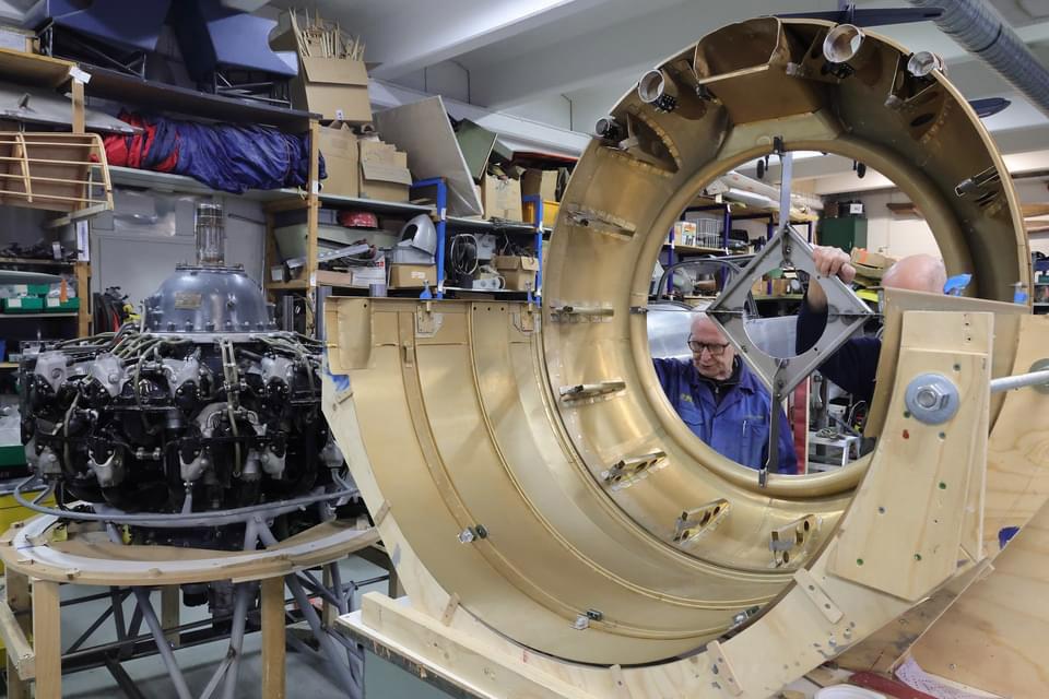
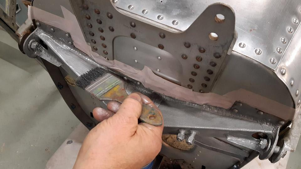
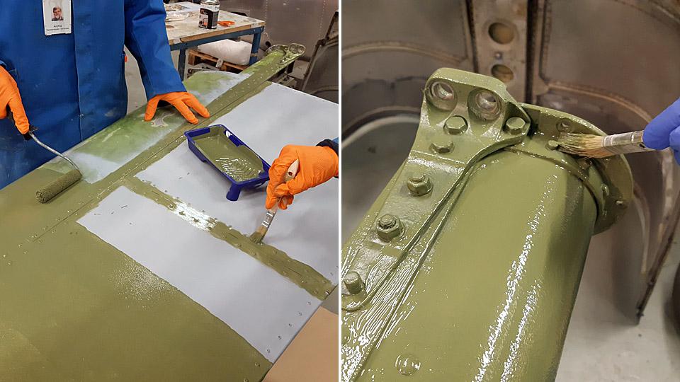
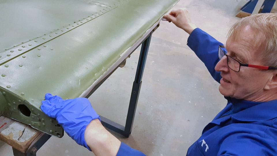
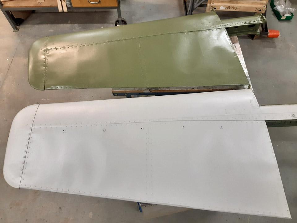
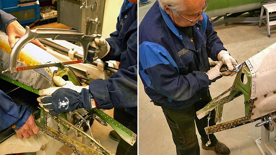
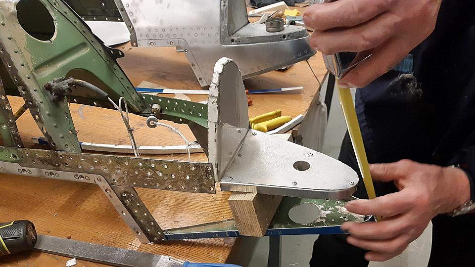
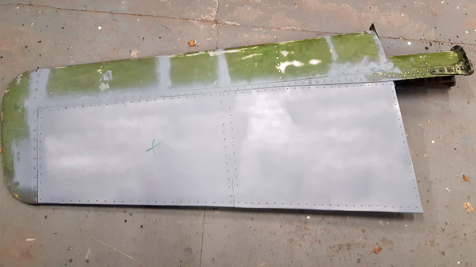
When the openings in the right-hand side wing root fairing were ready, the fairing was fitted in place. After that, the end of the horn for the exhaust air could be pushed into the opening in the fairing and fasten the other end of the horn to the oil cooler. It was noted that the exhaust air horn fitted its opening just like it should.
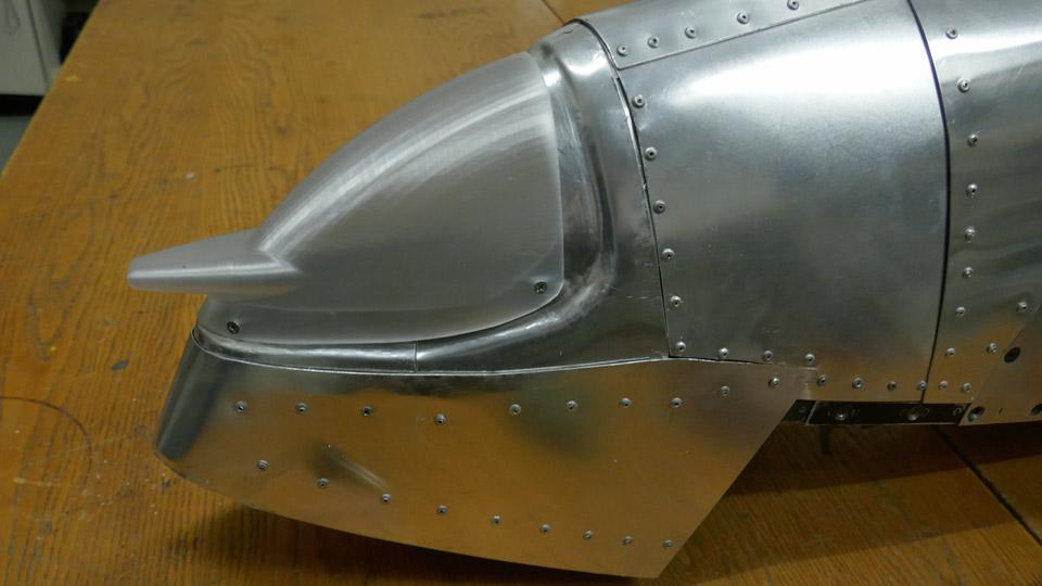
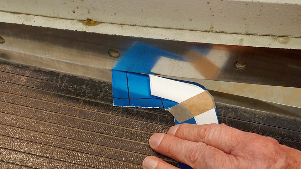
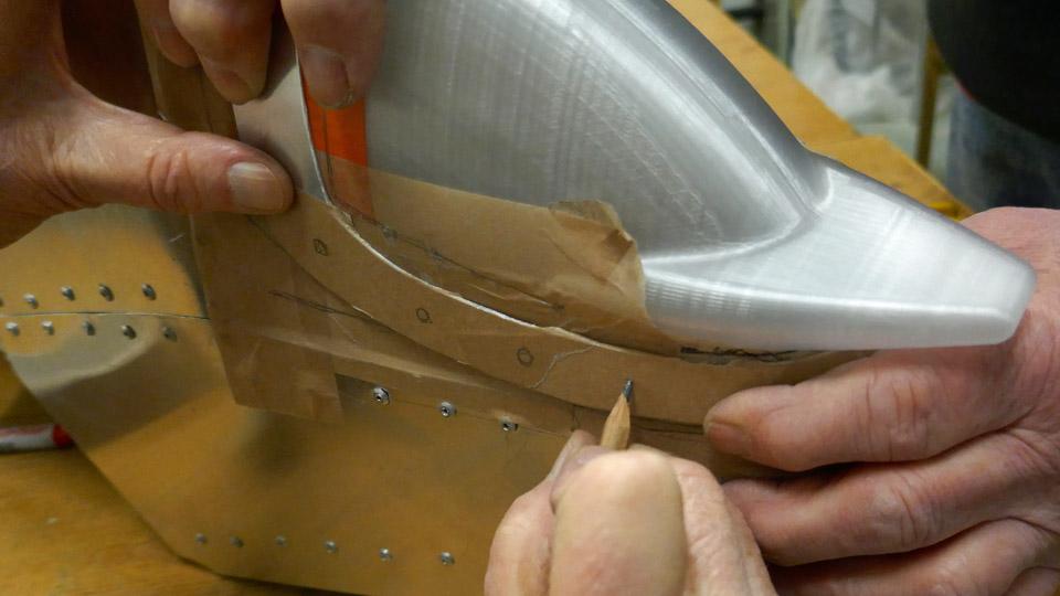
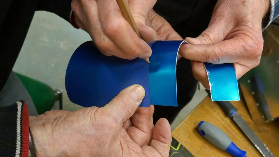
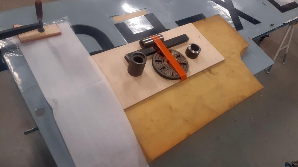
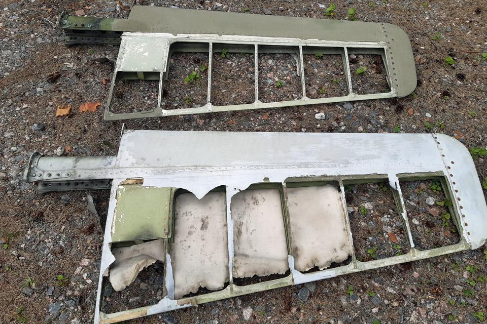
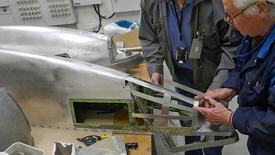
Left hand side photo by photo archive of Finnish Aviation Museum. Next in turn was the making of the cover for the space for the mouthpiece of the intake air horn. The mouthpiece of the horn is situated in the leading edge of the wing in an area limited by two ribs and the front spar. Cooling air for the oil cooler is taken through an opening in the wing’s leading edge. The horn for the oil cooler intake air is for the most part located under the left-hand side wing root fairing, but the mouthpiece of the intake air horn reaches outside the fairing edge.
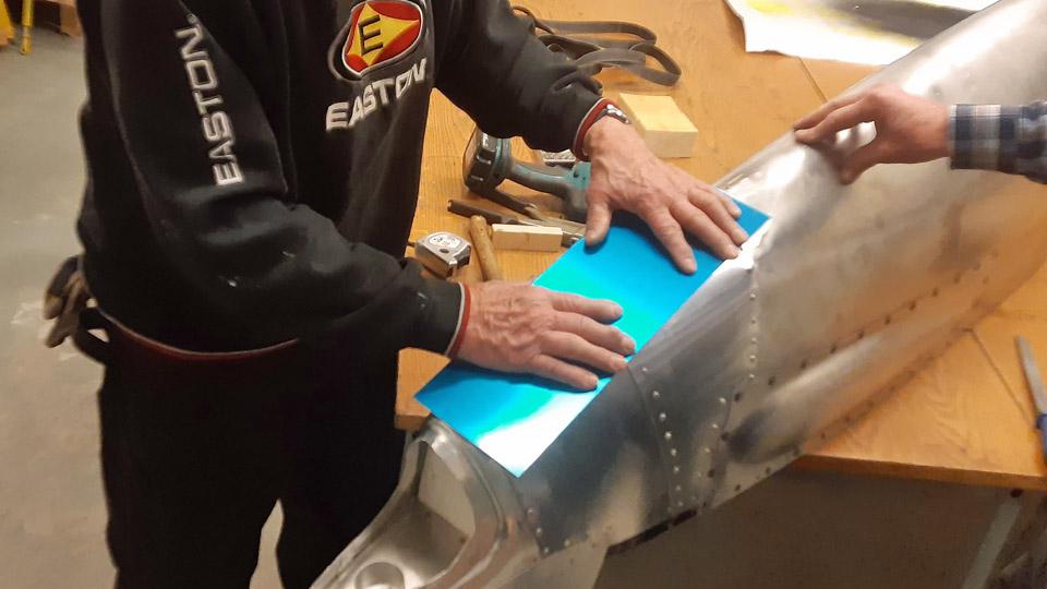
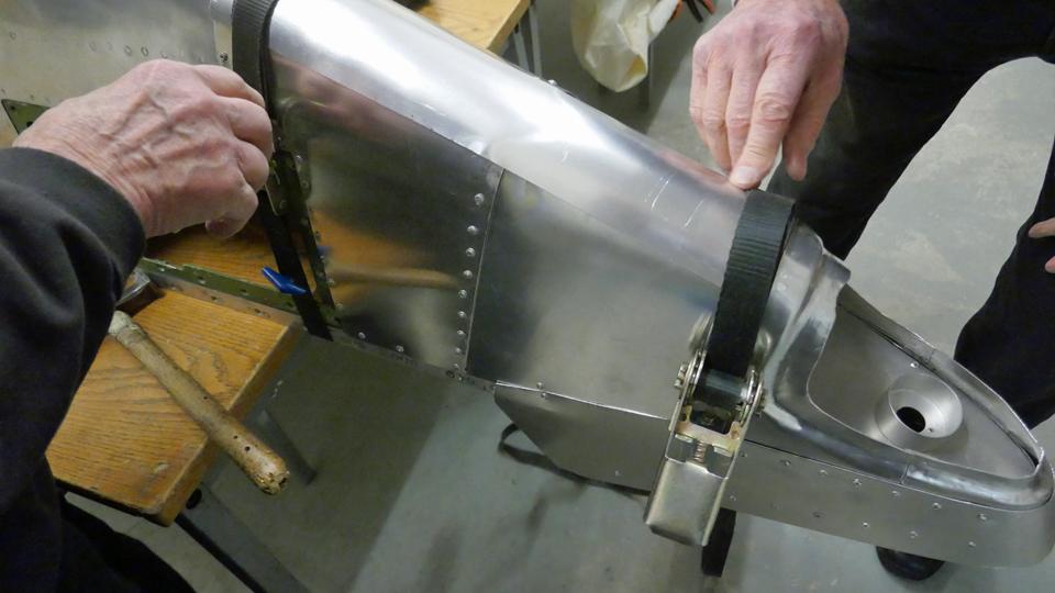
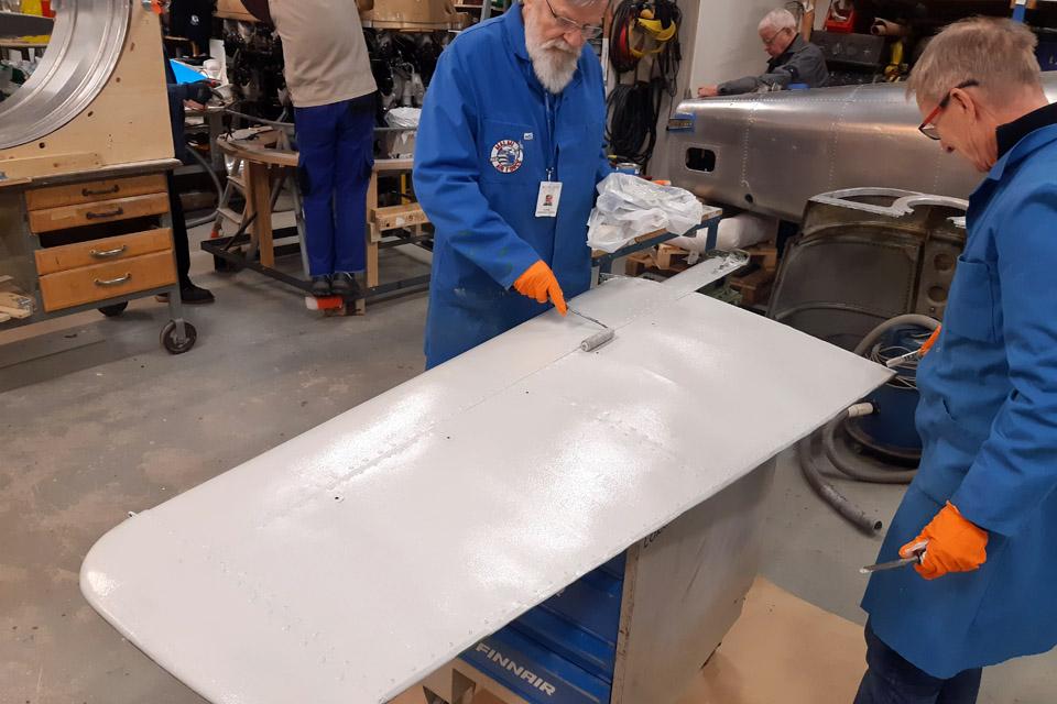
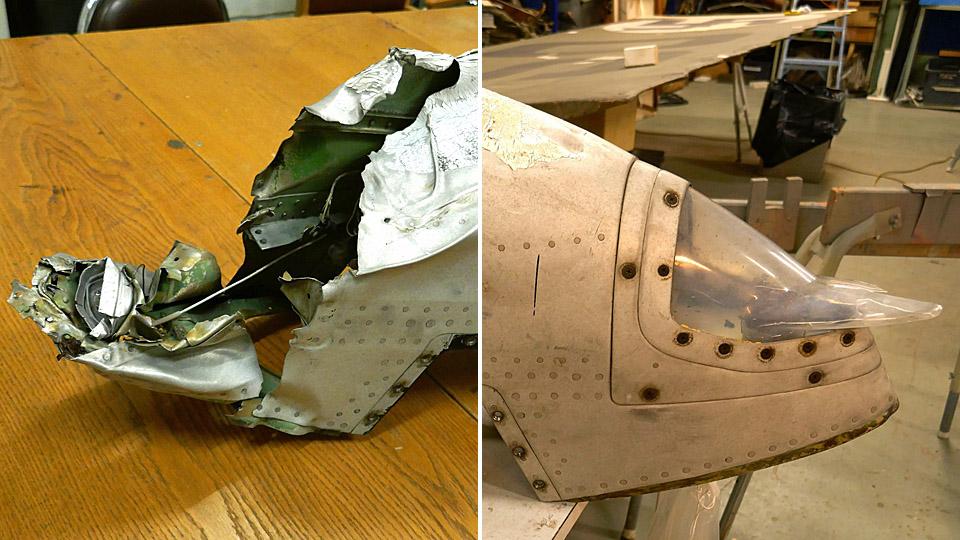
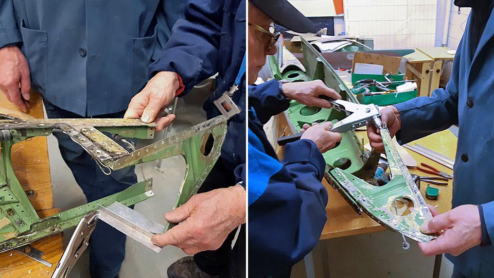
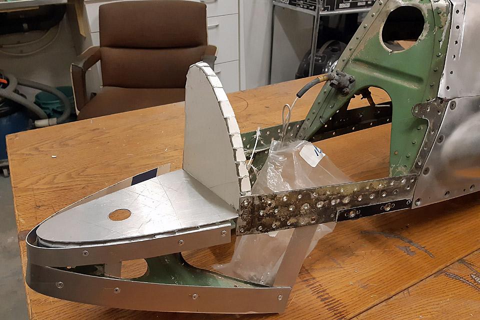
Photos by Heikki Kaakinen. When the intake air horn for the oil cooler and the left-hand side wing root fairing had been installed once again, we checked once more that the air intake horn’s mouthpiece was exactly flush with the wing’s leading edge. Now we could start to make the cover for the space for the mouthpiece of the air intake horn. The space will be covered with a shield made of aluminium sheet, with an opening for the air intake horn. The shield will be fastened to the wing ribs and the edge of the front spar.
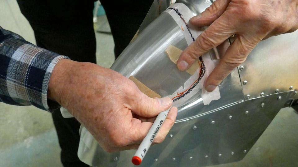
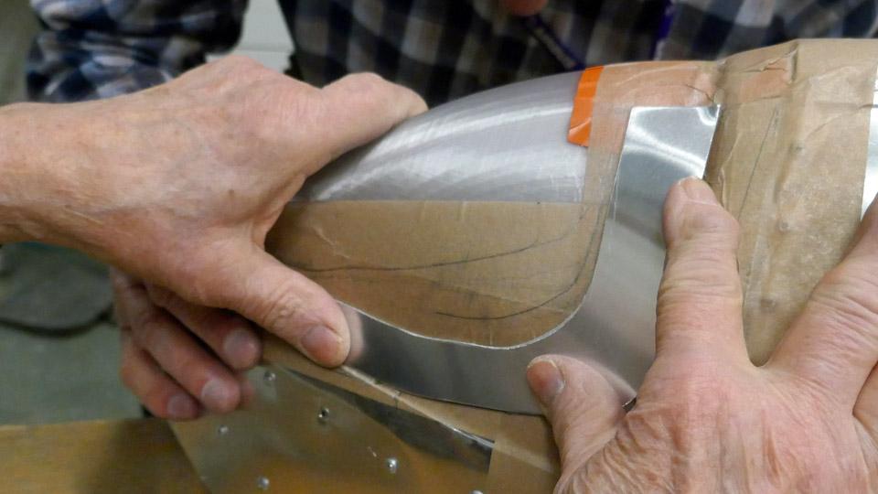
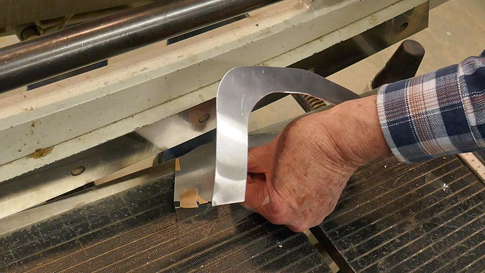
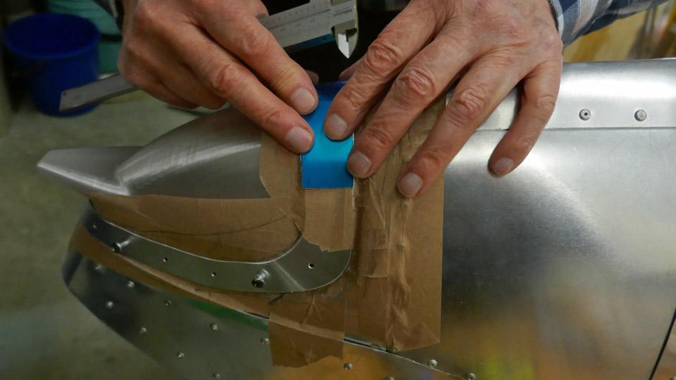
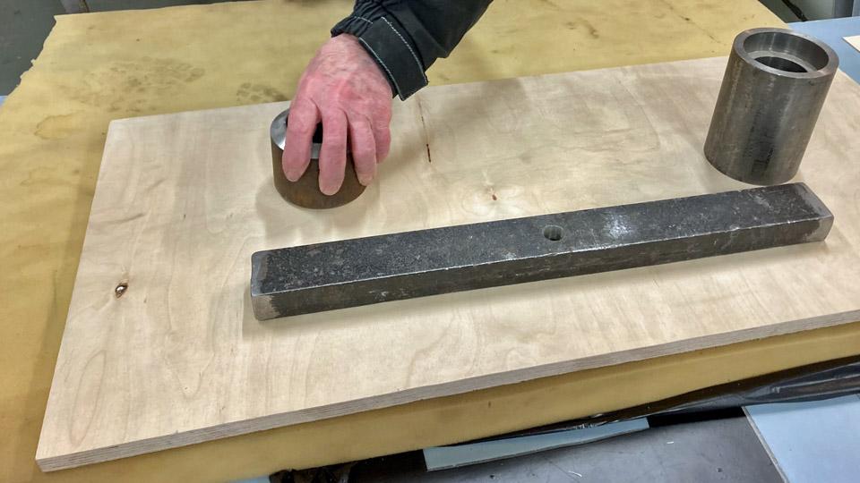
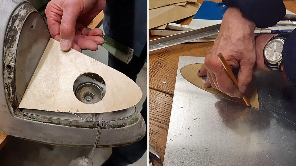
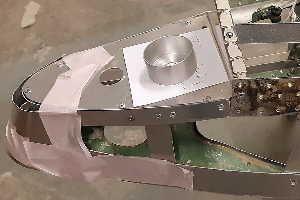
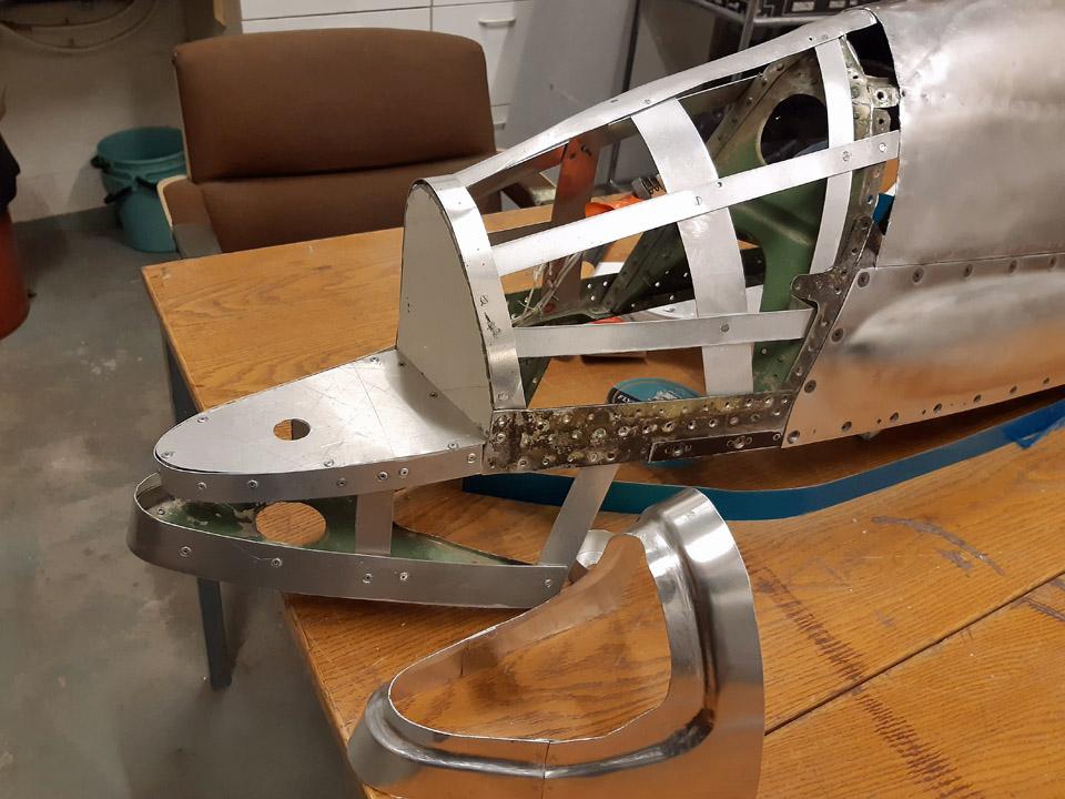
The blank for the shield was cut from 1 mm thick aluminium sheet. The blank was bent to match the leading edge shape. After that an opening for the air intake horn for the oil cooler was made. The half-ready shield was fitted to its place. It was observed to sit well. The edges of the opening of the shield were bent inwards by forcing.
Photo by Jorma Laakkonen.
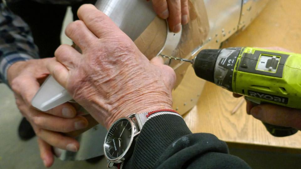
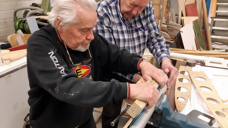
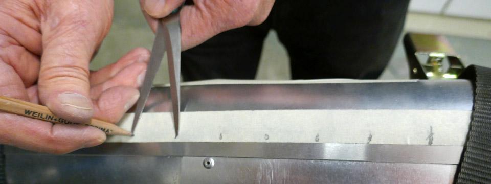
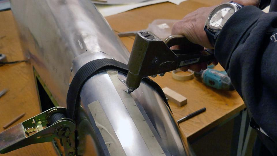
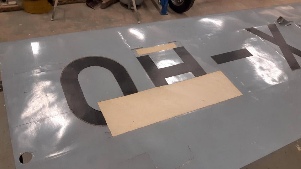
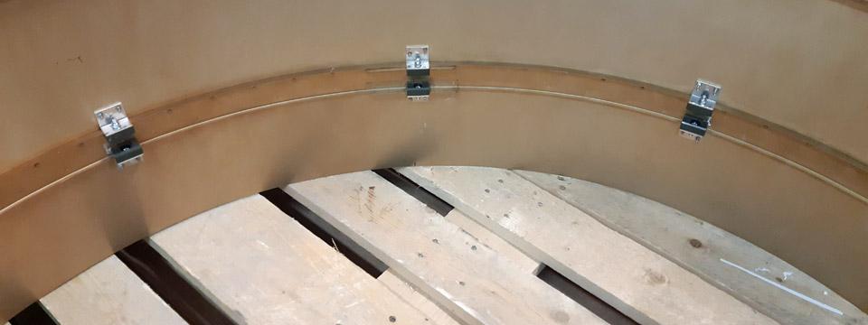
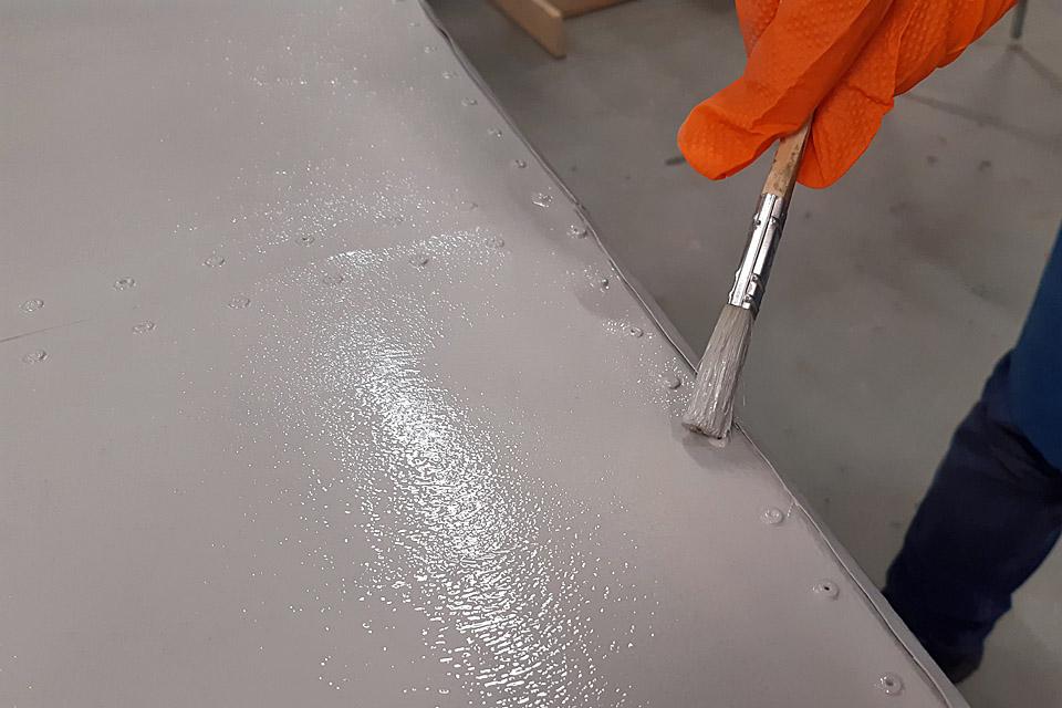
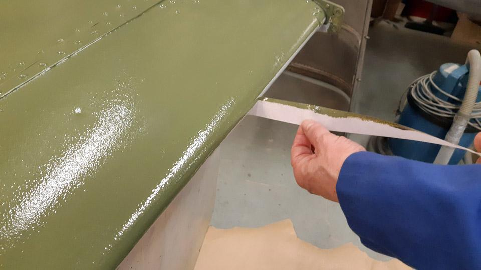
The aluminium shield covering the mouth of the oil cooler intake air horn will be fastened at its edges with screws and flange nuts to the wing ribs and the wing spar. On the fairing side the right-hand edge of the shield remains in between the stem fairing and the metal wing rib, i.e. it will be fastened to its place simultaneously with the edge of wing root fairing. Holes for screws were drilled at the edges of the shield. The holes were strengthened with “crickets” or brass strengthening rings.
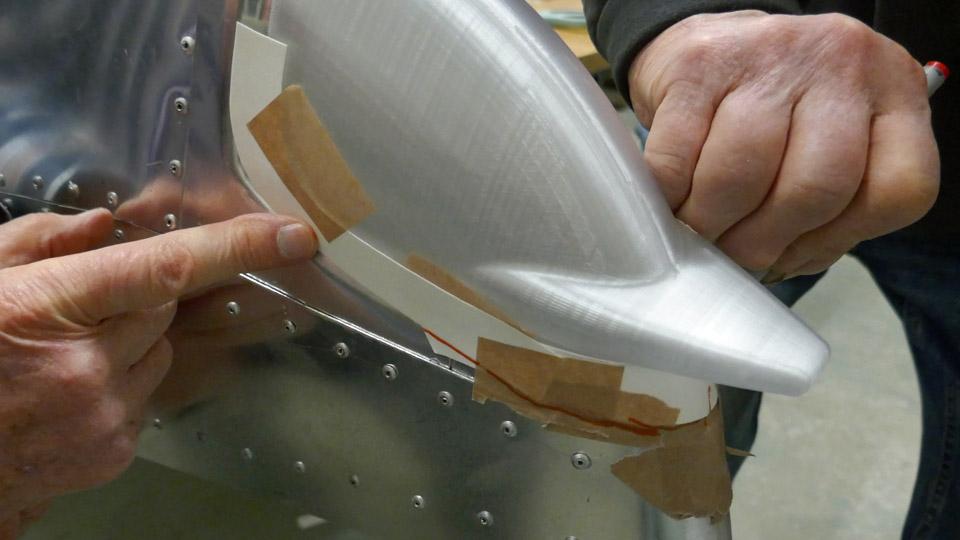
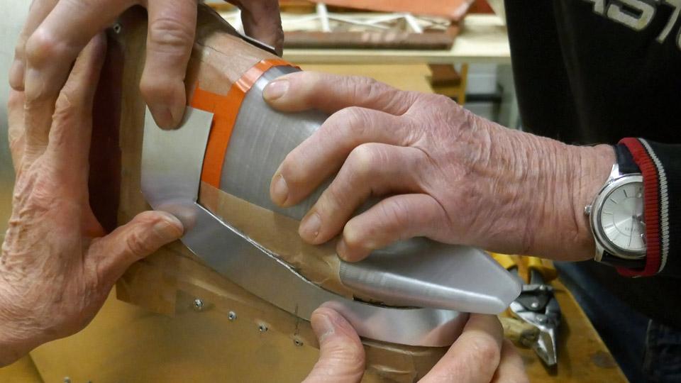
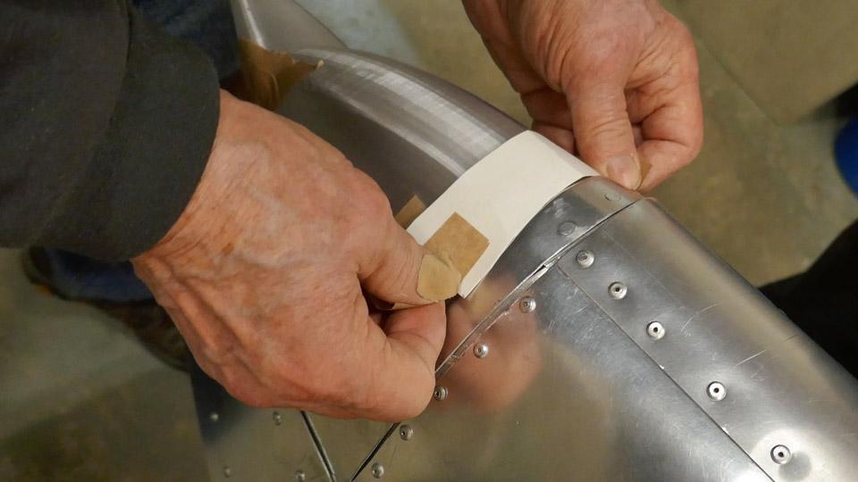
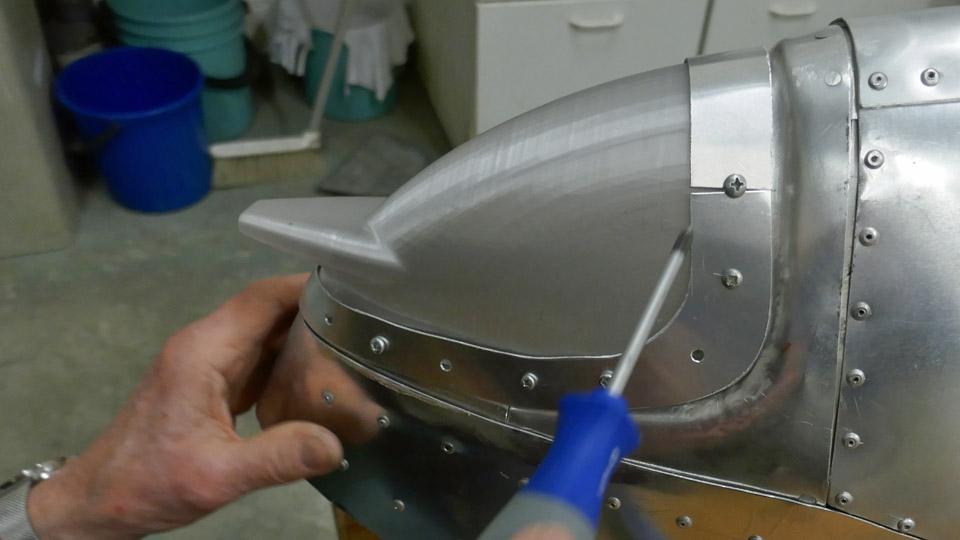
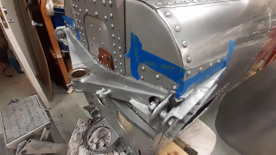
Photo by Heikki Kaakinen. The shield was now ready to be test-fitted together with the left-hand side wing root fairing. So the shield was screwed at its edges with a few screws to the leading edge rib and the front spar’s upper and lower edges. After this the left-hand side wing root fairing, next to the oil cooler, was fitted to place. The outer edge of the fairing curved snugly over the air intake horn’s mouthpiece shield’s edge. Assembling the wing root fairing and the shield needs only some fine adjustment. When the fittings of the oil cooler air intake and exhaust air horns, wing root fairings and the air intake horn mouthpiece shield are ready, the aluminium parts that haven’t been chromated will be taken to Patria Industries for yellow chromating. The chromating will take place at the beginning of August. By now it’s clear that the preplanned roll-out event of the MY-14 Myrsky fighter will be postponed. But, as they say, it’s worth while waiting for something good. Photos by Lassi Karivalo except if otherwise mentioned. Translation by Matti Liuskallio. |
|
Avainsanat: aviation history, restoration, MY-14, VL Myrsky, Tuesday Club |
The right-hand side wingtip of Caravelle III "Bluebird" is delivered to TurkuSunnuntai 26.5.2024 - Tuesday Club member The Caravelle III "Bluebird" (OH-LEA), on display in Turku, has until now been without the wing tip piece of its right-hand side wing. For about a year, the wingtip has been under repair and parts of it have been rebuilt at the Tuesday Club, working at Finnish Aviation Museum. The leading edge of the wingtip had been destroyed while the Caravelle, in SAS colours at the time and carrying registration SE-DAF, stood by the edge of Arlanda airport for decades. Probably some airport vehicle had bumped into the aircraft.
The repair work of the right-hand wingtip section was completed at the Tuesday Club, but it wasn’t taken to Turku until now. The wingtip was transported from Finnish Aviation Museum in Vantaa to Turku airport, to be assembled on “Bluebird’s” wing. The wingtip section is too large to be transported in an ordinary passenger car. It was packed properly and loaded on the Aviation Museum yard on a trailer. The journey towards Turku could begin.
The vehicle was welcomed at Turku airport by the Caravelle Turku restoration team. The team unloaded the wingtip from the trailer and carried it under Caravelle’s right-hand side wing to wait for assembly.
Right-hand photo by Reijo Siirtola.
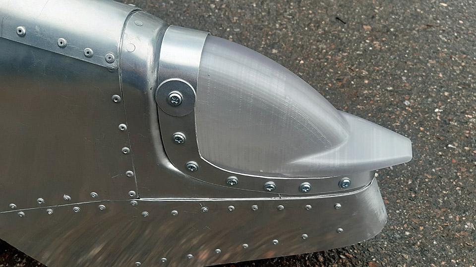
Now all Caravelle work allocated to the Tuesday Club have been completed. The work included repairing the nose bulkhead edge and the damaged radome, refurbishing and painting the wall panels of the flight deck and the corridor leading to the flight deck, repairing the glare shield above the flight deck instrument panel, building the frame for the navigation light on the right-hand wingtip and preparing the navigation light globes by 3D-printing.
Photo by Ismo Matinlauri. Furthermore, in 2022 we built stands for supporting the Caravelle’s fuselage and wings during the transportation from Arlanda to the former shipyard hall in the Pansio harbour area in Turku. We also restored the Caravelle III towbar, brought from Arlanda, which was in poor condition. The towbar is already in place, fastened on “Bluebird’s” nose wheel. Photos by Lassi Karivalo except if otherwise mentioned. Translation by Erja Reinikainen. |
|
Avainsanat: aviation history, restoration, Caravelle, OH-LEA, Sinilintu, Bluebird, Tuesday Club |
Caudron C.59 advanced trainer; covering of the horizontal stabilizerTiistai 14.5.2024 - Tuesday Club member Caudron C.59 was an advanced trainer used by the Finnish Air Force in the 1920s. The restoration of the individual aircraft CA-50 was commenced at the Tuesday Club in 2019. The work has advanced in stages. After the Finnish Aviation Museum acquired from abroad cotton fabric designated to covering aircraft, we could start covering the horizontal stabilizer of the Caudron, which had been waiting for some time. We had earlier refurbished the Caudron’s horizontal stabilizer, which had been in very poor condition, by taking it apart and reassembling it for covering.
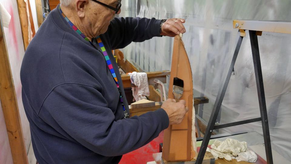
Prior to the covering, it was decided to lacquer with nitro cellulose lacquer the fabric strip covering, wound around the leading edge of the stabilizer. It was made of 50 mm wide linen band according to the original. By lacquering the band covering, the gluing of the covering fabric will be enhanced on the surface of the leading edge of the stabilizer.
Photo by Jukka Köresaar.
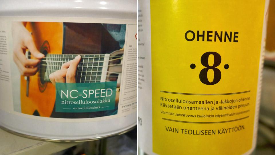
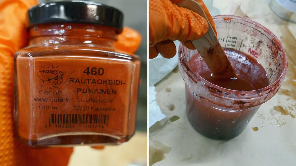
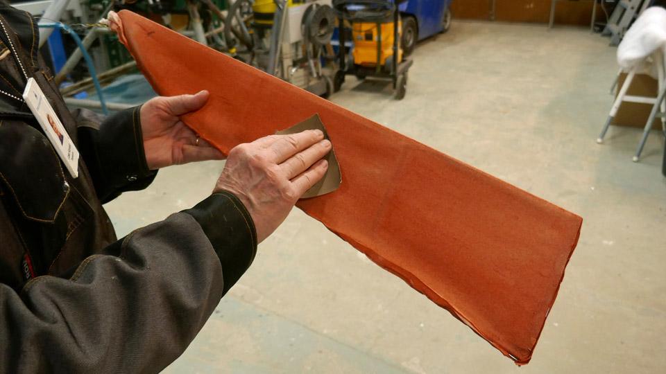
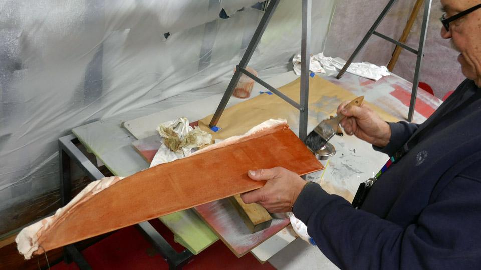
The linen band covering wound on the leading edge of the horizontal stabilizer was lacquered with 75% nitrocellulose lacquer. As lacquer we used NC Speed nitrocellulose lacquer, and it was tinted red with iron oxide powder. After the lacquer had dried, the edges of the linen band had, as we expected, risen as well as the fabric fuzz. So the band covering was sanded smooth, and another layer of lacquer was applied. Even after the re-lacquering, the leading edge band was uneven and the band had to be sanded once more, after which it was lacquered with 100% nitrocellulose lacquer. So the linen band wound around the leading edge had been smoothed, and we could start covering the horizontal stabilizer.
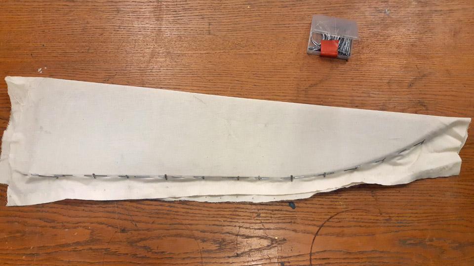
The width of the horizontal stabilizer is 60 cm and its length 120 cm, so a 130 cm wide piece was cut from the 140 cm wide cotton fabric. This way the fabric has enough working allowance to work both in length and width way. The fabric was wound around the stabilizer, which was laid the table, so that the lapels of the fabric reached past the horizontal stabilizer’s trailing edge. We meant to make a bag out of the fabric, which would be open at the trailing edge.
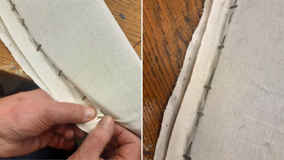
To achieve this, at both ends of the stabilizer the lapels were joined with pins. The lapels were then sewn together with a sewing machine, along the line of the pins. So the fabric was formed to be a bag, open at the trailing edge. When the ends had been sewn, the fabric was turned inside out, leaving the sewing seams of the lapels inside the fabric bag.
The fabric bag, open at the trailing edge, was drawn on the horizonal stabilizer. The sewing of the fabric was very successful, because the fabric bag had become tight, or rather “skin-tight” on the horizontal stabilizer. Now it was time to sew together the still open trailing edge fabric lapels. For the sewing extra parts of the lapels were cut off, so that the lapels met at the outer edge of the trailing edge batten.
To keep the lapels of the fabric in place when they were sewn together, the fabric was fastened with staples from a stapler at the side of the trailing edge batten. The lapels of the fabric were sewn together with a thin double yarn cotton thread. As a needle we used a curved needle, which was handy for this kind of sewing.
Photo by Antti Laukkanen. The sewing of the covering fabric lapels was done so that the seam formed a continuous serrated shape. When the lapels had been sewn, the covering fabric formed a closed bag over the horizontal stabilizer.
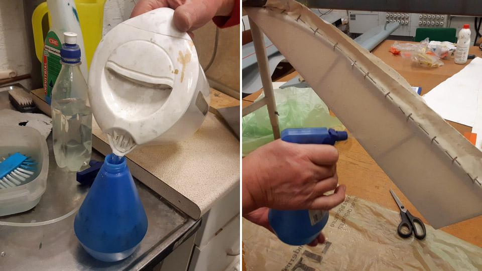
Photo by Antti Laukkanen. The next phase in the work was the water-tightening of the fabric. The stabilizer covering fabric was soaked with boiled, but cooled water, and was left to dry. With water-tightening, the fabric is pre-tightened, because when dried the covering fabric has already tightened a few percent on the stabilizer.
Photo by Antti Laukkanen. The proper tightening of the covering fabric to resemble a drum head, will be made with nitrocellulose lacquer. Before tightening the covering the fabric needs to be sewn on the stabilizer ribs. The sewing will be done by following the original 1920s Caudron stabilizer sewing method. This way of sewing was documented, when the decayed covering fabric was stripped off the Caudron’s stabilizer. According to that, the covering fabric was sewn onto the fabric strips, which were fastened to the stabilizer ribs, with tacking interval of about 3 cm. The fabric strip was for its part tied to the rib’s surface with an edging ribbon. We had done similarly, when refurbishing the stabilizer.
The places of the stitches were marked at each rib on the surface of the covering fabric, using a thin template made of plywood. The stitching places of the sewing needle were marked on the fabric surface with a thin felt pen, through the template holes. Using a curved needle and double yarn thin sewing thread, the covering fabric was sewn stitch by stitch to the edging ribbons that ran along the ribs. A regular space between the stitches made it possible that the needle occasionally pierced the edging ribbon which tied the fabric strip to the rib. When the sewing had been done, the staples could be removed from the fabric surface.
The covering fabric was now sewn to the horizontal stabilizers’ ribs, both on the upper and the bottom surface, so it’s time to move on the next phase of the covering. There the horizontal stabilizer’s covering fabric will be tightened to drum head tightness with nitrocellulose lacquer. As lacquer we use NC Speed nitro cellulose lacquer. Applying the lacquer is started with 25 % thinned lacquer, and from there in stages to the full 100% nitrocellulose lacquer. Photos by Lassi Karivalo except if otherwise mentioned. Translation by Matti Liuskallio. |
|
Avainsanat: aviation history, restoration, Caudron C.59, CA-50, Tuesday Club |
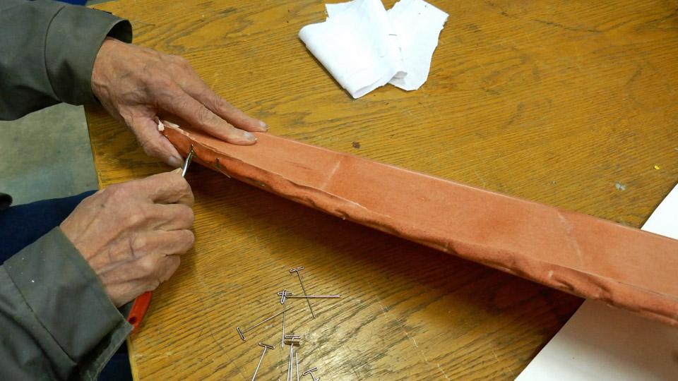
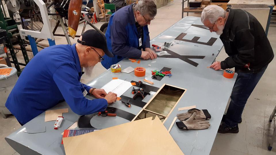
Covering of Ressu's (Snoopy) rudderMaanantai 6.5.2024 - Tuesday Club member When the preliminary tasks concerning the covering of the experimental aircraft Hietanen OH-XEA rudder had been done, the proper covering could be commenced. The rudder covering is done with cotton fabric meant for covering aircraft. The covering will be done the same way it had originally been done in the 1960s.
The covering got started by setting the metal-framed rudder on the fabric, which was spread on the table. The edge of the fabric was wrapped around the right-hand side metal tube of the leading edge and sewed onto it. The sewing was done with thin cotton thread, using a suitable curved or hooked needle.
After the fabric had been sewn to the leading edge right-hand tube, the rudder was turned over on the table, so that the metal frame of the rudder was left under the fabric. The fabric that was attached to the right-hand leading edge, was drawn over the leading edge and left-hand side to the trailing edge the of the rudder, where the lapel of the fabric was left hanging over the table edge.
A metal bar was attached to the hem of the fabric hanging over the table edge. With the aid of the bar the fabric, resting on the left-hand side of the rudder, was tightened. At the top and bottom edges of the rudder the lapels of the fabric were tightened with small clamps to the edge of the table. When the fabric was tightened this way, the water tightening of the fabric was started. The fabric was soaked through with boiled water. When drying, the fabric shrinks a little. The proper tightening of the covering fabric will be done after the water tightening with nitrocellulose lacquer.
The tightening lacquering of aircraft covering fabrics is carried out in a process with several phases. The tightening lacquering is started with a 25 % thinned nitrocellulose lacquer. From that the process continues with intermittent sanding to 50, 75,100 -% nitro lacquer. After each phase the fabric is sanded free of the fuzz brought to the surface by the lacquer. From phase to phase the covering fabric will shrink more and more. The end result is a covering fabric tight as a drum head. The sufficient degree of tightening is easy to verify by tapping the surface. It’s customary to pigment or colour red the lacquer with iron oxide powder. This will help to recognize which area has been dealt with the lacquer and which not.
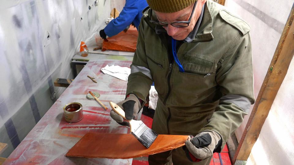
When the water-soaked fabric on the left-hand side of Ressu’s rudder had dried, 25 % thinned NC-Speed nitrocellulose lacquer was applied on the surface of the fabric. As a thinner NC-Speeds’s own Thinner-8 was used. The lacquer was tinted red with red iron oxide powder. After the lacquer had dried, the weights were detached and the rudder was turned around, after which the unlacquered side of covering fabric was drawn tightly under the right-hand side of the rudder. The lapel of the fabric was sewn to the leading edge of the right-hand side metal tube, i.e. the same, where the lapel of the fabric had been sewn in the first place. The covering fabric was now around the rudder like a bag.
Now the right-hand side fabric of the rudder in its turn was water-soaked. After that this side, too, was lacquered with 25% NC-Speed tightening lacquer. After the lacquer had been dried, the rudder’s lower edge, triangular shaped in cross section, was covered by sewing the lapels of the fabric onto the tubes in the rudder’s lower edge.
The tightening of the covering fabric continued with applying a second layer of 25 % lacquer on the rudder surfaces. Because the fabric didn’t start to tighten in the manner we had hoped, the rudder was lacquered a third time over with 25% lacquer. From this point on we advanced in stages to three times applied 50% and twice applied 75% NC Speed lacquering. In this manner a sufficient level of tightness was achieved, so that the fabric strips protecting the stiches of the covering fabric at the edges of the rudder can be fastened. The protecting strips will be glued to the leading, upper, and bottom edges of the rudder. No strip will be needed at the trailing edge because there’s no seam in the fabric there. Of course we could glue a strip there, too, because it would make it more resilient.
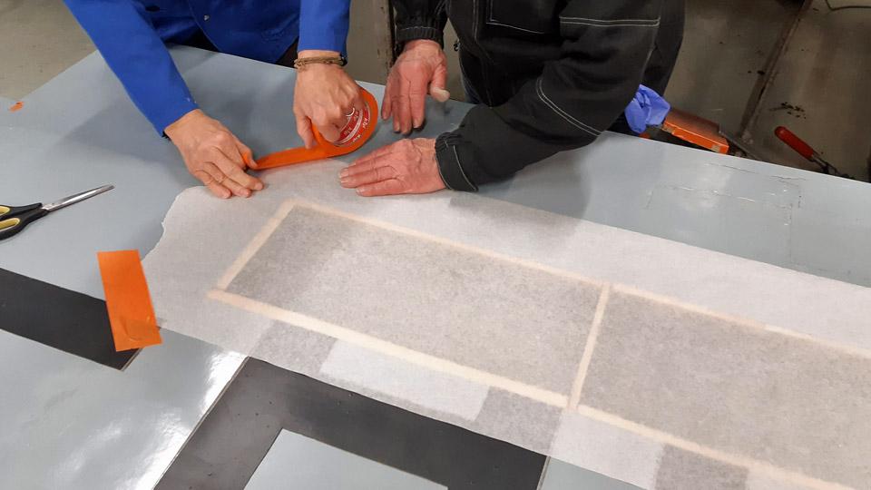
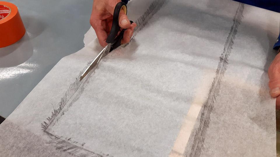
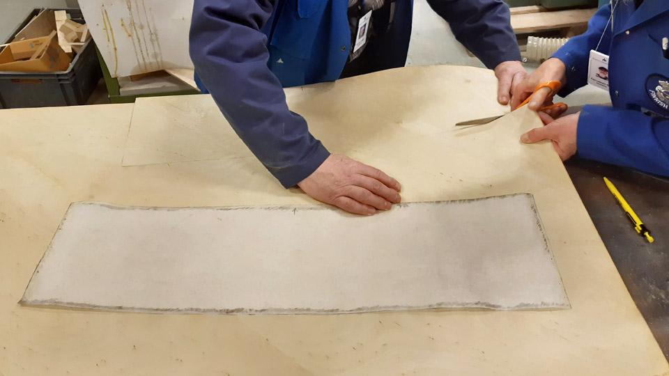
The protective strips were cut off the same covering fabric with which the rudder was covered.
The cutting was done with serrated zig-zag scissors. The serrated edge of the protective strip will stick better to its base, i.e. the lacquered surface of the covering fabric compared to the straight edge.
The protective strips were glued to the rudder with 75% nitrocellulose lacquer. First the area of the protective strip was lacquered, after which the strip was pressed onto the wet lacquer. The strip was applied with lacquer so that it became thoroughly soaked with lacquer. The strip was pressed against is base and brushing away air pockets or bubbles from under the strip. At the same time it was made certain that the serrated edges were tightly glued to the surface of the covering fabric.
After the strips had dried, their surfaces were sanded smooth paying attention especially to the serrated edges. The lacquering and sanding were repeated three times, after which the protective strips and especially their serrated edges were worked so smooth, that feeling with your finger gave you no sensation of the strip edge on the surface of the covering fabric.
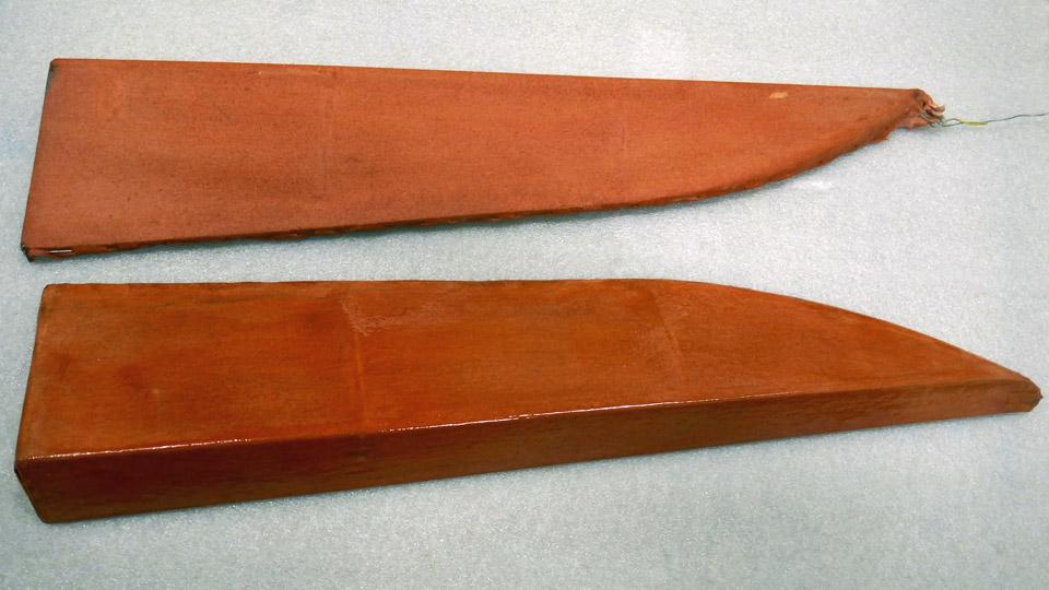
After fastening the protective strips, the whole rudder was lacquered once with 100% nitrocellulose NC Speed lacquer. The covering fabric of the rudder had now reached the stage where it was as tight as a drum head and thus ready for painting. According to Ressu’s original colour scheme it will be light bluish grey. Photos by Lassi Karivalo. Translation by Matti Liuskallio. |
|
Avainsanat: aviation history, restoration, Tuesday Club, Hietanen HEA-23b, OH-XEA, "Ressu" |
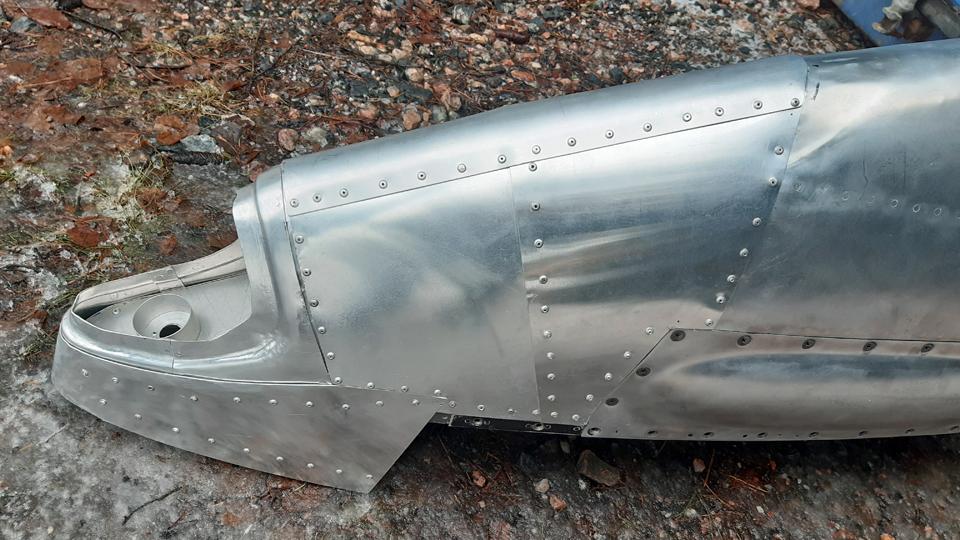
Caravelle right-hand wingtip is finalized with the navigation light globeLauantai 27.4.2024 - Tuesday Club member When the new leading edge had been built to replace the destroyed right-hand side wingtip leading edge on the Caravelle III (OH-LEA Bluebird), we could begin the installation of the navigation light globe into its place on the leading edge. We don’t have the original navigation light globe because it has been destroyed together with the wingtip. We could not find a globe as a spare part either, so we had to make one. We chose to do this by 3D-printing. We used the partly broken navigation light globe from the left wing as a model. A new globe was printed for the right wing and also for the left wing navigation light.
The new navigation light globe was installed on the OH-LEA Bluebird’s left-hand wing earlier in the summer of 2023. The right- hand wing, however, had to wait until March 2024 for its new globe to be put already in early into place after the new leading edge of the destroyed wingtip had been finished.
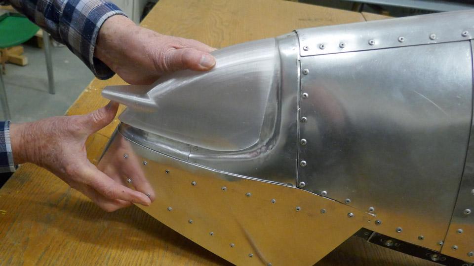
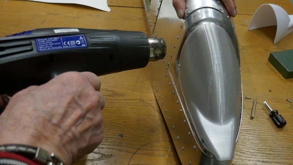
The 3D-printed navigation light globe is made of stiff plastic, and in the beginning it didn’t fit properly into place. We heated the globe with a hot air blower so that it could be moulded to fit into its mounting on the wingtip. The globe was fastened tentatively on the edges of the mounting with a couple of screws. This was necessary for holding the globe in place while making the fastening frame. The globe is fastened on the aluminium edge of its mounting with a frame. The frame has holes for screws, and it presses tightly against the sides of the globe, and the screws in the frame holes are tightened through the globe edge into the aluminium edge underneath.
Diverging from the original solution, we decided to make the fastening frame for the globe from two parts. This made it easier to build the frame. Nevertheless, the frame we made will cover the most part of the navigation globe edge. A connecting piece will be needed on the top of the globe to connect the ends of the frame.
When the globe had been fastened with a couple of screws, broad paper tape was fastened on its edge. The shape of the globe frame was drawn on the tape. Based on the drawn line, a model for the frame was made of cardboard. The model was taped on a 1 mm thick aluminium sheet, which had already been pre-cut into the frame shape. After this we began to modify the sheet with a cutter to match the shape of the cardboard model.
The aluminium frame was test-fitted into place and modified several times. Gradually the frame reached its final shape and it rested against the lower edge of the globe as §planned. When the desired shape had been reached, the blue plastic film which had protected the aluminium surface was removed from the frame.
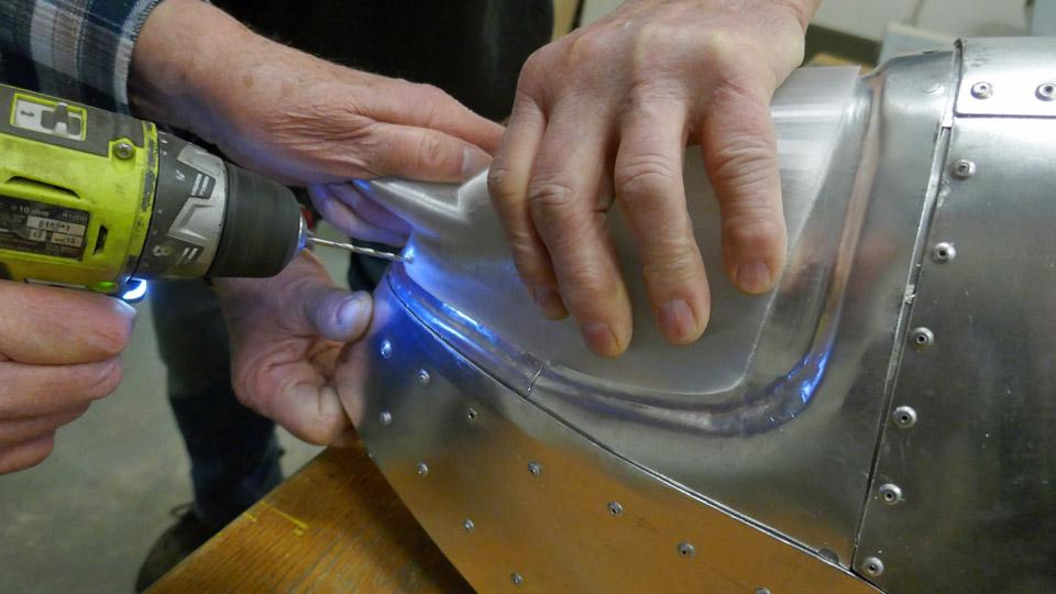
A strip of paper tape was fastened on the surface of the finalized fastening frame for marking the location of the fastening screws at regular intervals with a pencil. Holes for the fastening screws were drilled at the marked locations, then the screws were fastened one by one. This made the navigation light globe press into its place between the fastening frame and the edge of the globe mounting. Now the navigation light globe on the right-hand side wingtip was in place.
The last phase was to make the 5 cm connecting piece between the fastening frame ends on the top of the navigation light globe. First a cardboard model was made of the connecting piece. The connecting piece was cut and moulded from aluminium sheet, following the model. When the blue plastic covering had been removed from its surface, the connecting piece was fastened between the fastening frame ends, using two screws with washers. Finally the screws were tightened.
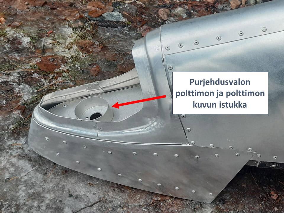
Under the globe, out of sight, is the socket for the navigation light bulb and its green glass globe. The socket was lathed from aluminium and installed into place at the Tuesday Club. The Caravelle’s right-hand side wingtip is ready for housing a powered navigation light, if there is need for it at some point.
Now the Caravelle Bluebird’s right-hand side wingtip had been completed. Re-constructing the destroyed leading edge took a whole year. The wingtip can be delivered to Turku to be assembled on the Caravelle Bluebird, which is on display near the passenger terminal at Turku airport. Photos by Lassi Karivalo. Translation by Erja Reinikainen. |
|
Avainsanat: aviation history, restoration, Caravelle, OH-LEA, Sinilintu, Bluebird, Tuesday Club |
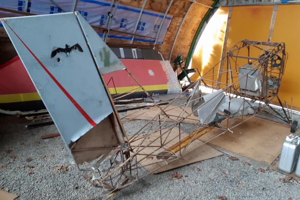
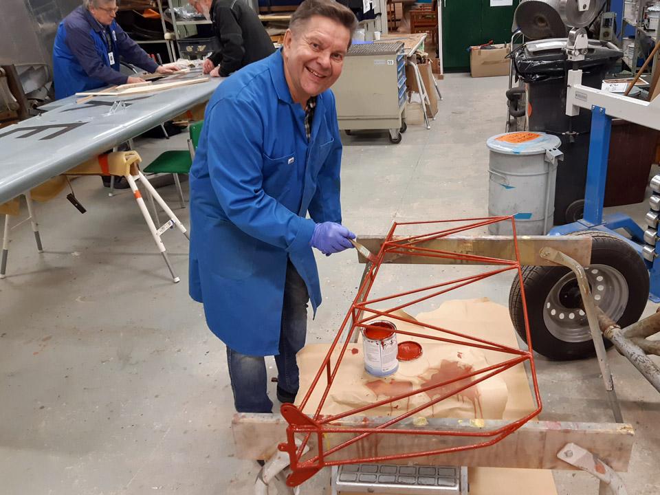
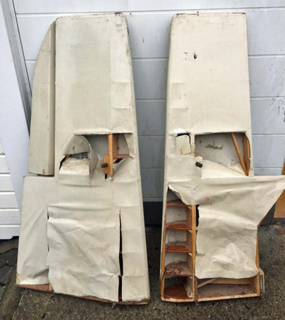
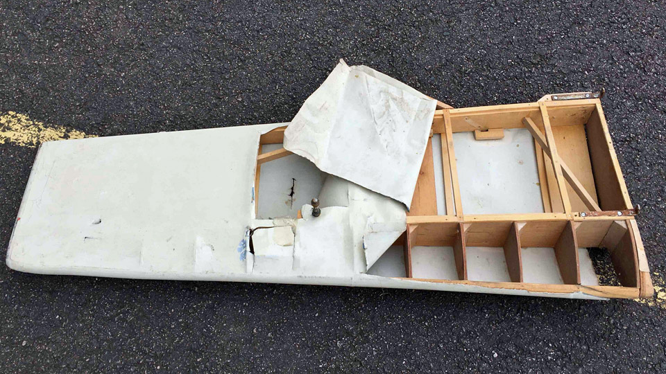
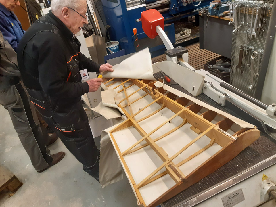
The Ressu (Snoopy) rudder covering preliminary work assignmentsSunnuntai 21.4.2024 - Tuesday Club member The IMY Tuesday club has continued its work with the Snoopy (Ressu). Planned and built by the Hietanen Brothers from Turku, the mixed structure experimental aircraft Ressu from the 1960s is next in line for the rudder’s canvas covered steel tube structure to be restored.
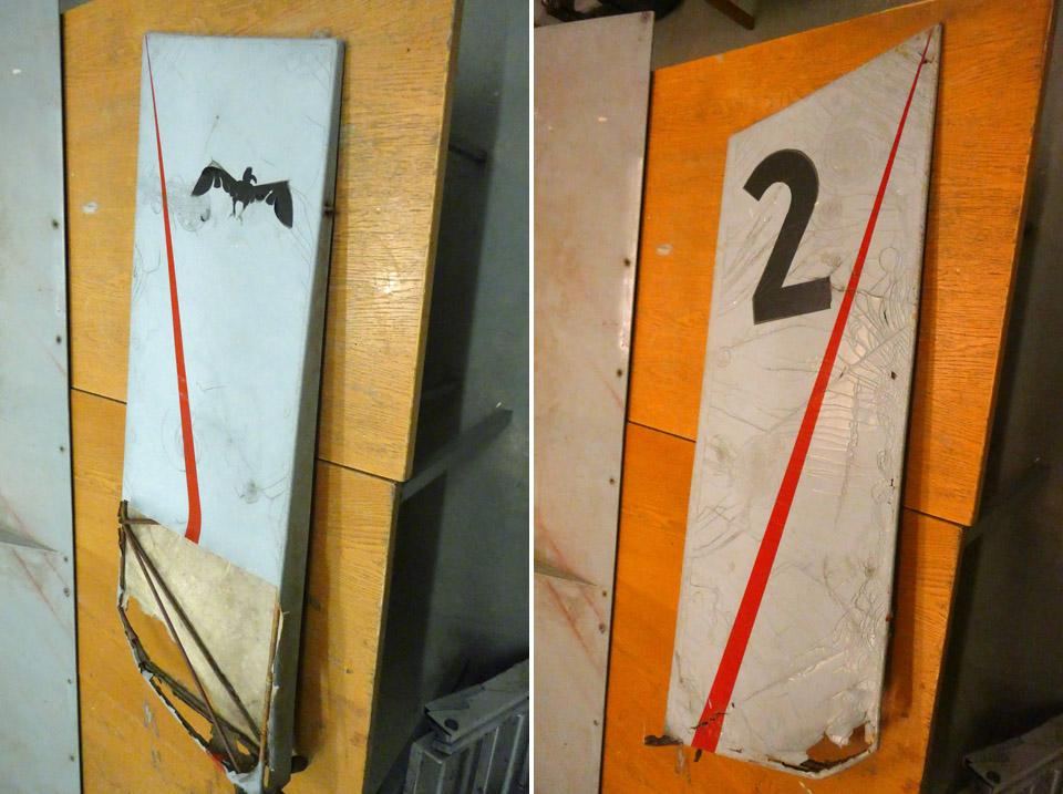
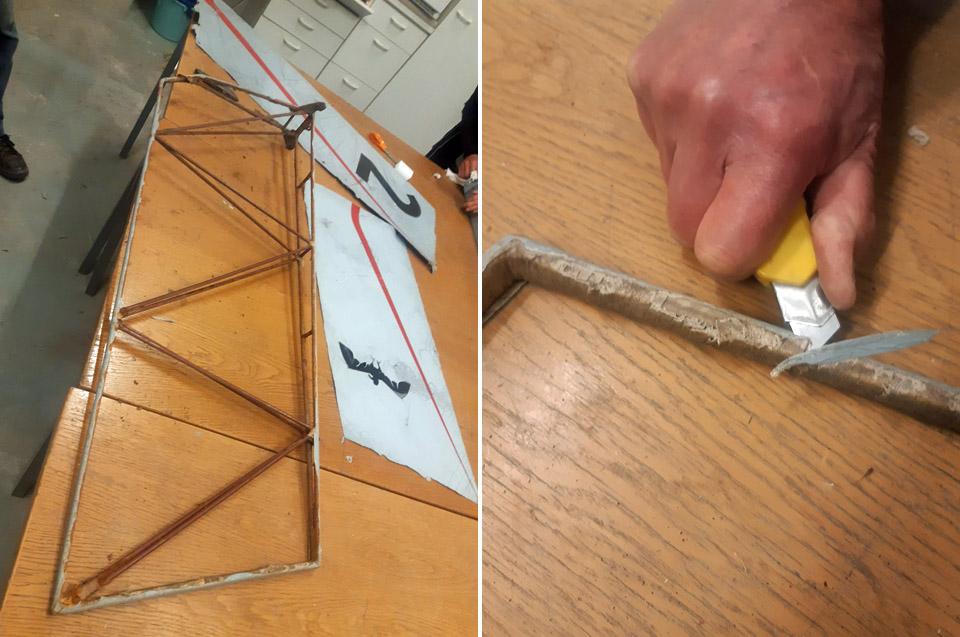
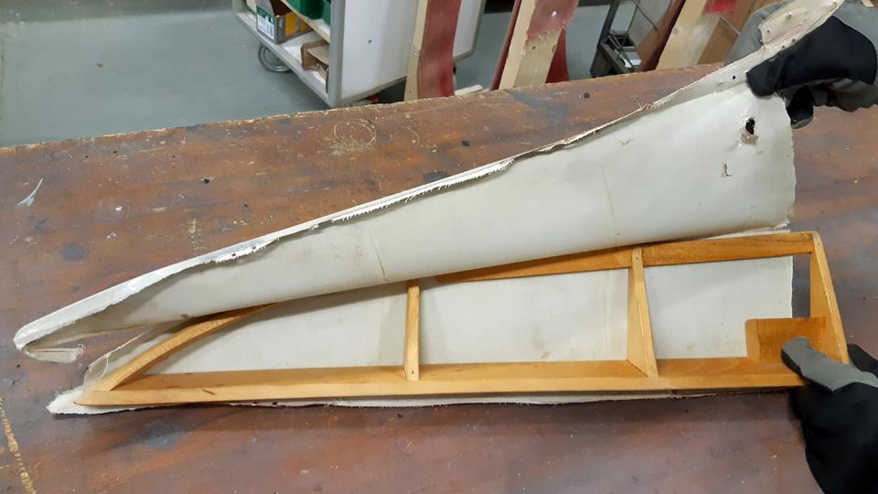
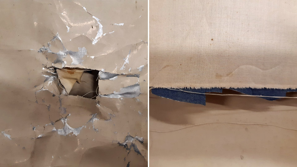
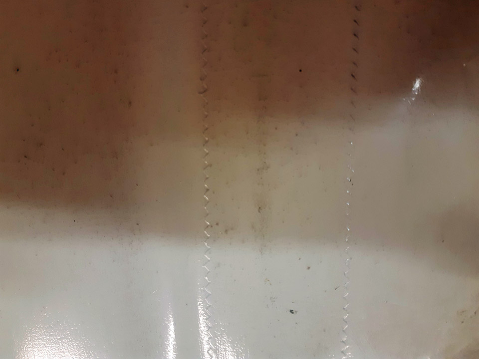
For the restoration the rudder was detached from the fuselage. The fabric covering was in a fragile shape, and the paint finish of the canvas badly crackeled. On the left-hand side the covering is fairly intact, but on the right-hand side a large piece of covering is missing on the lower edge. From this unexpected opening it could be seen that the covering canvas had been sewn onto the rudder frame outer tubes only, but not onto the cross tubes. The outer ring metal tubes had been covered with 20 mm wide cotton edging ribbon, by winding it the tightly along the tube. This was a common way to avoid the covering fabric to be attached to form a direct contact with metal. The fabric, that was sewn to the metal structure, had been tightened drum tight with nitrocellulose lacquer, after which the surface had received a light blue coat of paint. Finally the rudder had been treated with red speed stripes, a black number 2 and a bird figure.
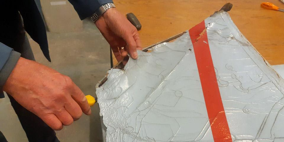
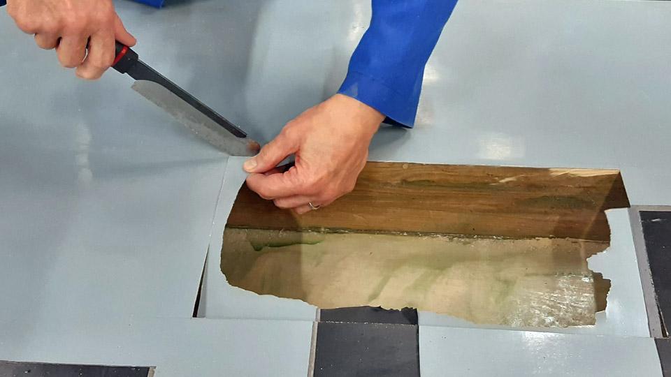
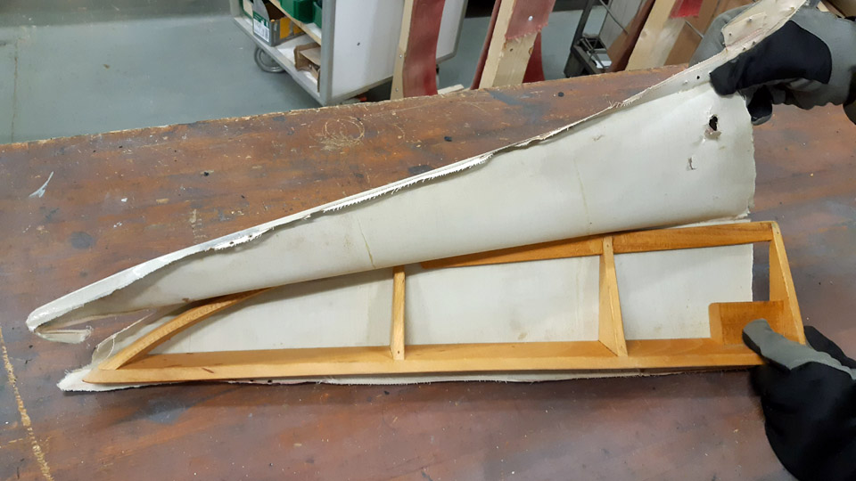
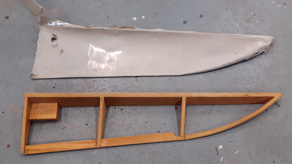
Because the Ressu’s rudder covering fabric was in a bad shape and partly broken, we decided to cover it completely anew, complying the old manner of doing it, however. The old covering fabric had to be detached from the steel frame of the rudder by cutting it off with a knife, because the fabric had glued itself tightly to the edging ribbons around the tubes. After detaching the covering fabric, the edge ribbons around the metal tubes were also removed.
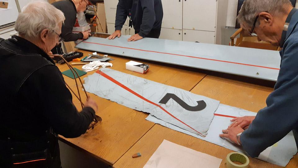
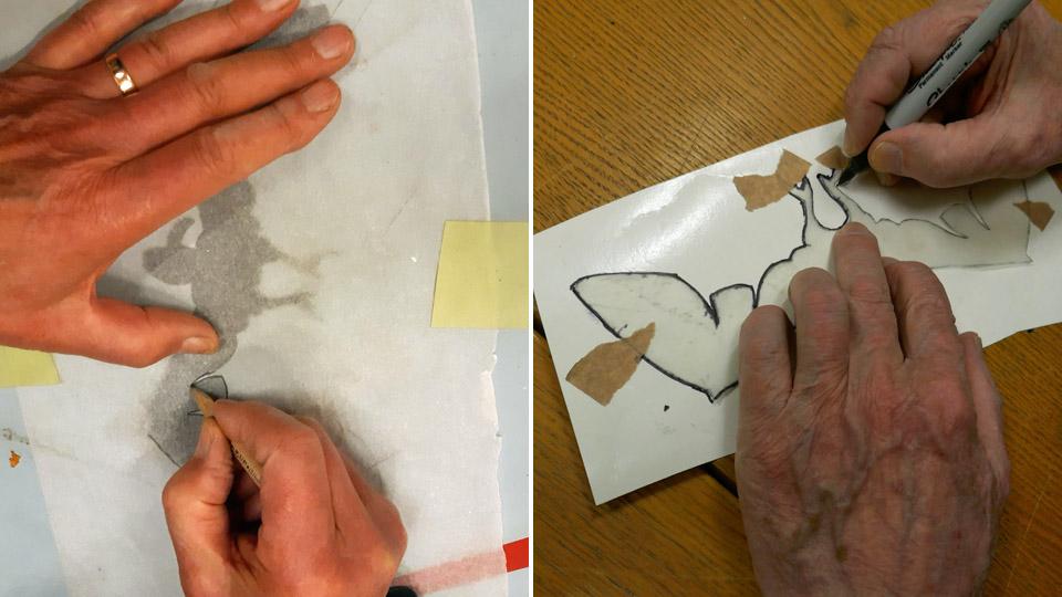
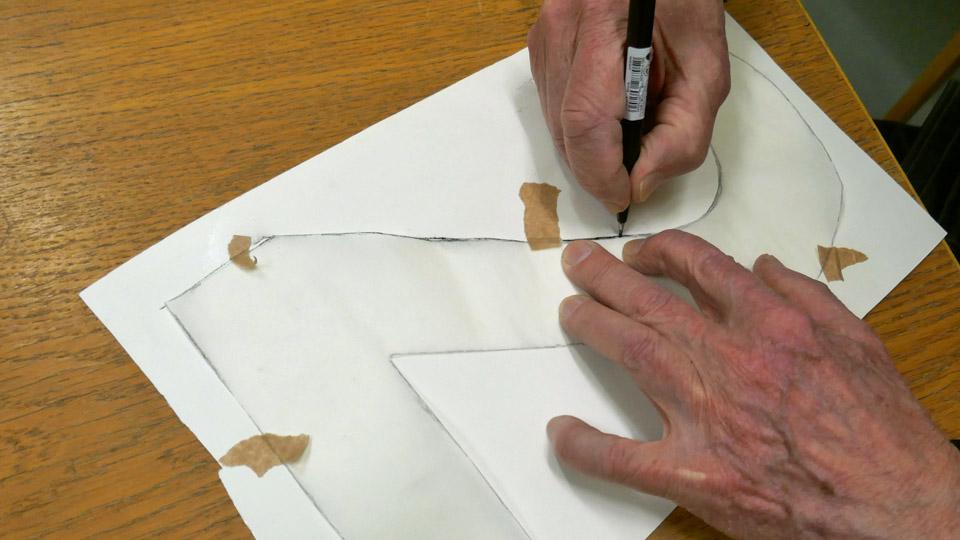
The red stripes of the rudder’s covering fabric and the left-hand side black number two and the right-hand side black bird were copied on transparent rice paper. After that the bird and the number were transferred onto sturdy cardboard to wait for the final transfer of these symbols onto black contact plastic, and their fixing onto the surface of the new covering fabric.
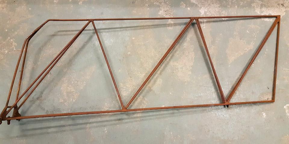
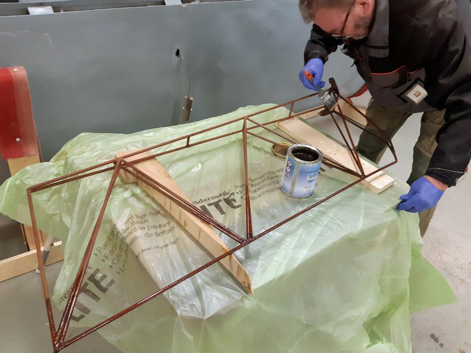
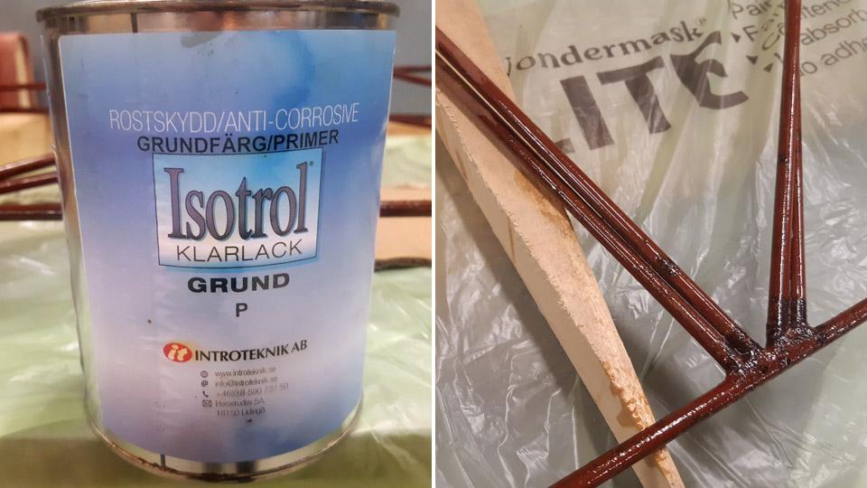
The work with the rudder’s metal structure was continued with doing away with the rust on the tube surfaces. Luckily the tubes weren’t badly rusted or corroded. The rust was sanded off with sanding paper, however, so that the tubes weren’t ground to pure metal. The transparent Isotrol-lacquer can be applied as primer even though the surface is still a bit rusty. The shielding cover of the Isotrol- lacquer will stop the rusting process. During the sanding it had been noticed that the rudder had originally been painted red. The paint had most probably been the red Ferrex, used widely in the 1960s to stop rusting.
The rudder frame structure was primed thinly with the transparent Isotrol -lacquer. Owing to the lacquer, the tube surfaces came out beautifully clear and the red paint applied on the surfaces rose up even more gloriously. After a light buffing, a layer of red Isotol paint was applied on the bright Isotrol lacquer, emulating the original red surface paint.
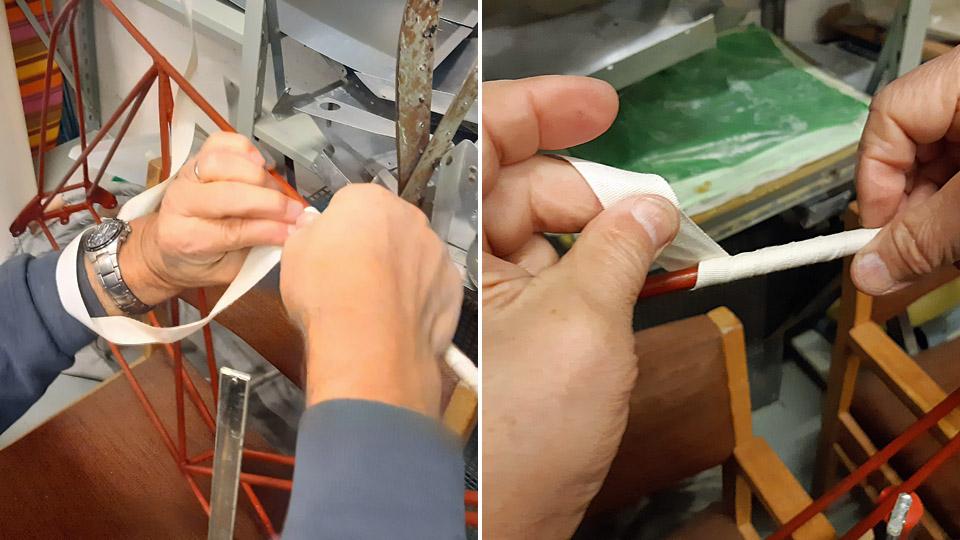
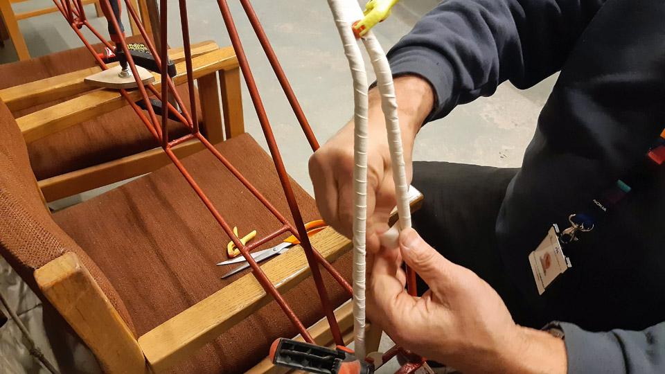
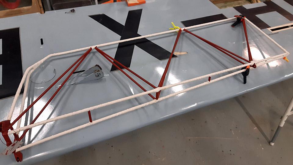
When the rudder frame had dried, we started to cover the steel tubes by winding 20 mm wide cotton edging ribbon around the steel tubes. Thus we’ll prevent, according to the original concept, the covering fabric being in direct contact with the surface of the steel tubes. By hurrying slowly we managed to wrap the cotton ribbon around the outer tubes of the frame. Ressu’s rudder in now ready to begin the fabric covering proper. Photos by Lassi Karivalo. Translation by Matti Liuskallio. |
|
Avainsanat: aviation history, restoration, Tuesday Club, Hietanen HEA-23b, OH-XEA, "Ressu" |
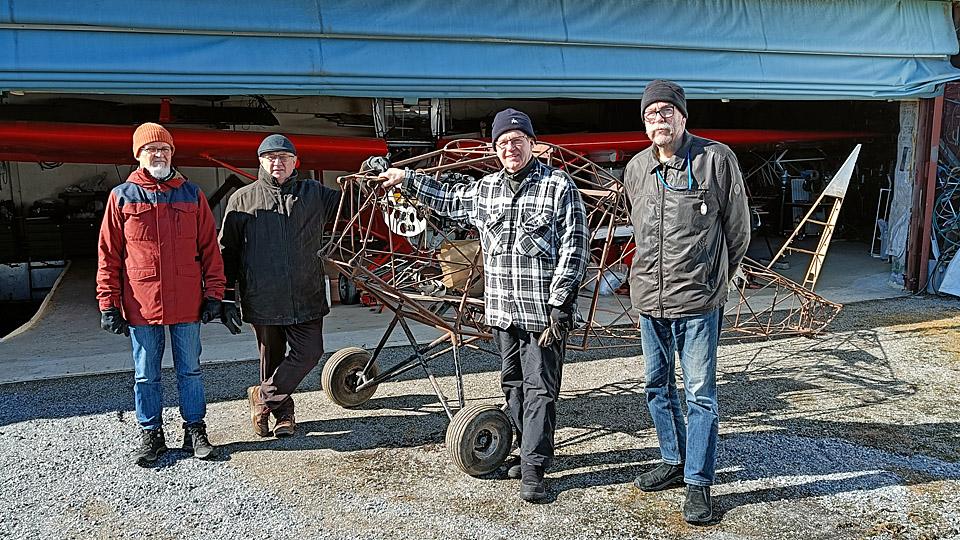
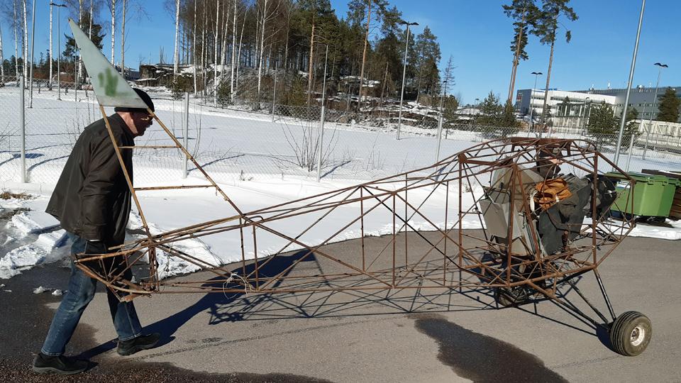
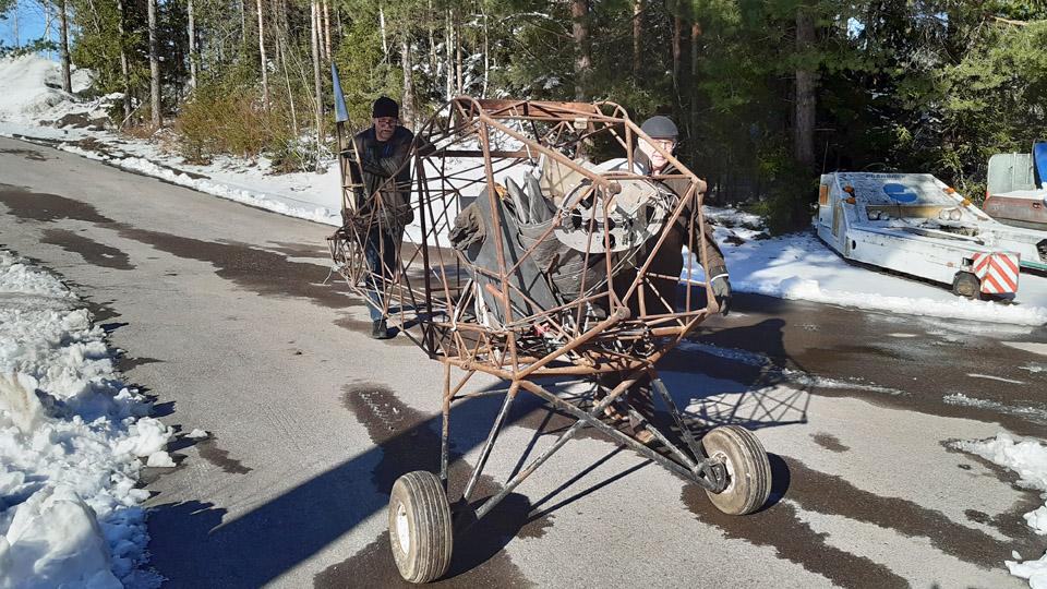
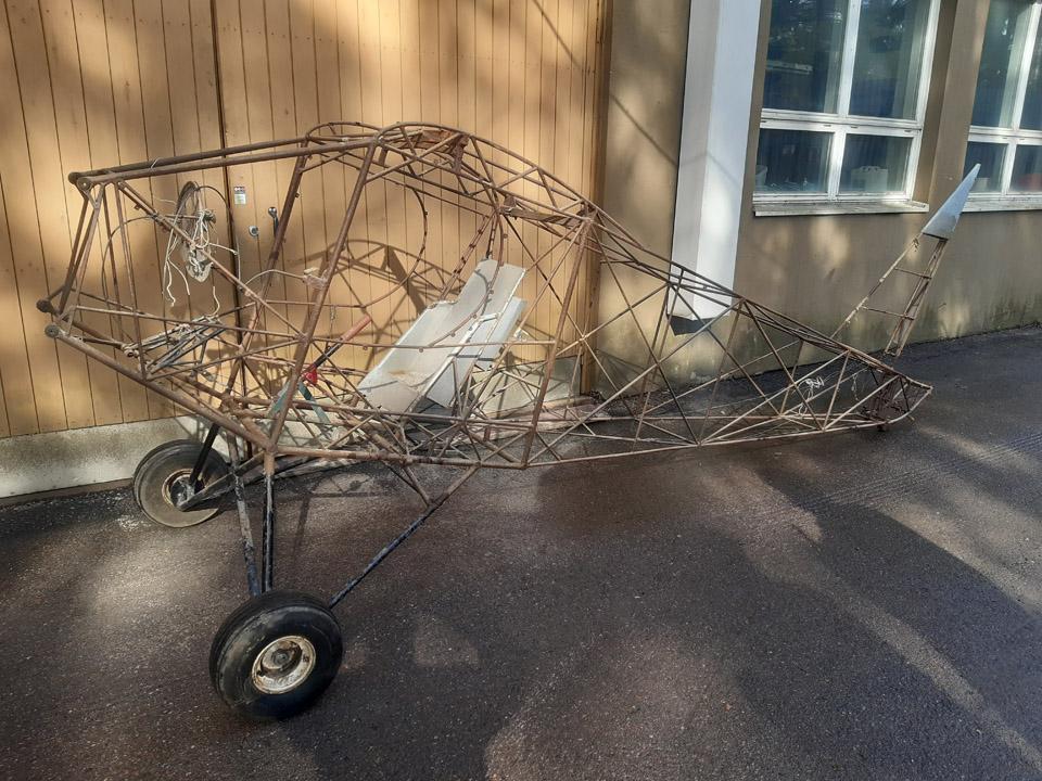
Ressu's fuselage frame moved from Lemu to VantaaTiistai 9.4.2024 - Tuesday Club member On Thursday April 4th, the Tuesday Club task force set off towards Lemu in the Turku region to fetch the OH-XEA “Ressu” (“Snoopy”) fuselage frame to Finnish Aviation Museum to be restored by the Tuesday Club. The OH-XEA is an experimental aircraft, designed and built in the late 1960s by brothers Hietanen, Esko and Ari. Since last autumn we have been working on the restoration of Ressu’s horizontal stabilizer, elevator, rudder, and wing struts. This work will be ready soon and we could pick up the Ressu’s fuselage frame from Lemu to be restored. The Ressu fuselage, stripped entirely of its fabric covering, has been stored in the hall of Martti Mattila, an aviation enthusiast from Lemu. Last autumn we fetched the Ressu’s wings and tail parts from the same place. On our way to Lemu we made a detour via Turku Airport, to Caravelle “Bluebird”, which is on display there. In Helsinki we had picked up a Super Caravelle First-Class double seat frame, which we left to the Caravelle. The aim is to build four rows of seats in the “Bluebird” cabin and an adapted group of First-Class seats. From the Airport we continued to Lemu, where we arrived soon after noon.
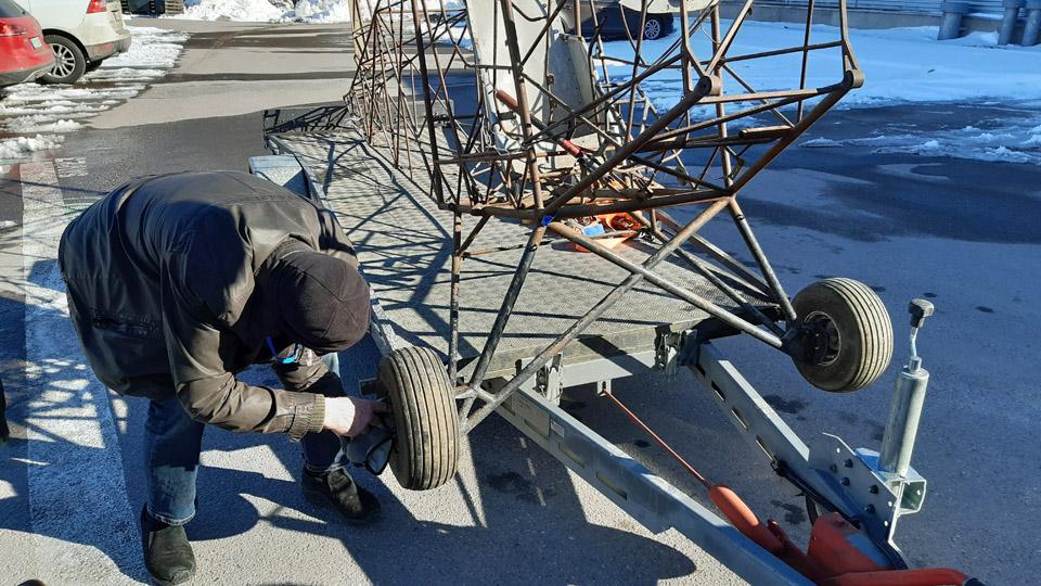
Photo by Martti Mattila. Martti Mattila had already prepared the Ressu fuselage frame for pick up by fastening two wheels with pneumatic tyres, borrowed from a ride-on lawn mower, on the ends of the landing gear axle and by moving the fuselage frame outside the hall. Due to the wheels the fuselage frame was easy to move. The lawn mower wheels are exactly the suitable size for Ressu. Before the fuselage fame was moved next to the trailer to be loaded, the pick-up team posed for a group photo.
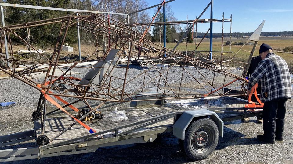
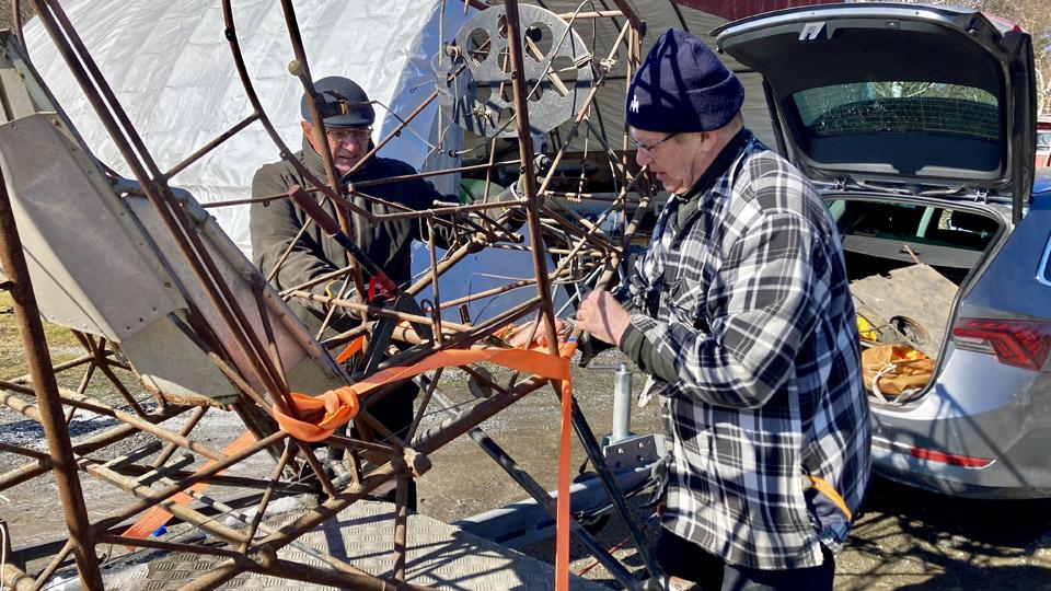
Photo by Matti Kainulainen. When the rather light fuselage frame was lifted on the trailer, we noticed that the landing gear with its wheels was too wide to fit inside the trailer sides. We solved the problem by unfastening the wheels and the landing gear fitted just nicely inside the trailer sides, and the fuselage frame rested on the trailer floor on its wheel flanges.
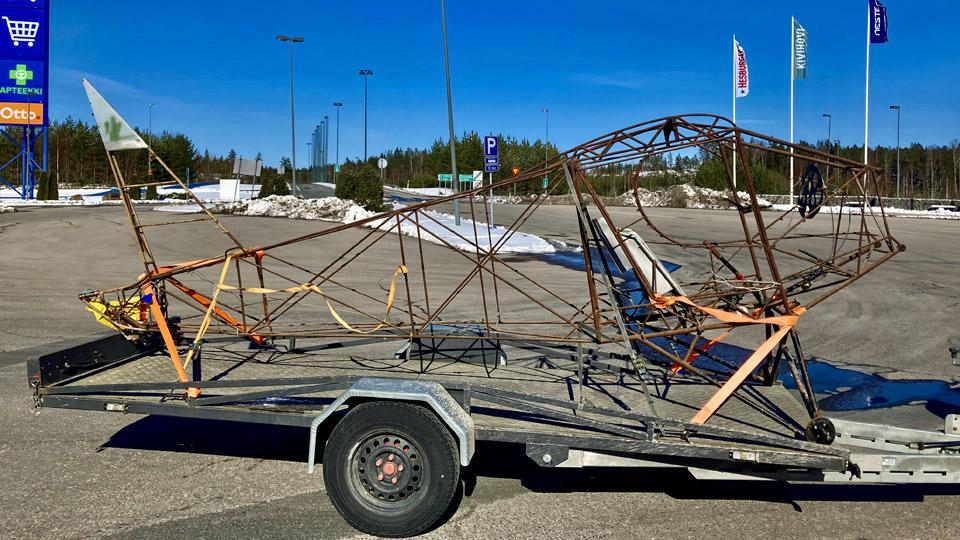
Photo by Matti Kainulainen. We fastened the fuselage frame on the trailer with the nose of the aircraft facing forward. The trailer we had at our disposal was long enough to hold almost the whole length of the Ressu’s fuselage frame. The tail reached just slightly over the tailgate. The fuselage frame was secured tightly on the trailer, front and aft, using cargo straps. We topped up our cargo by adding a security banner on the tail. We also loaded the rest of the Ressu stuff from Mattila’s hall, such as the cockpit plexiglass windows and the seat belts. Many thanks to Martti Mattila for accommodating Ressu and its parts in his hall since last June.
Photo by Matti Kainulainen. We spent some time with Martti Mattila, listening to him talking about his ongoing aircraft engine project. Based on what we heard, we can say that Mattila is a person with multiple skills when it comes to aircraft engines and aircraft in general. He has designed and built an aircraft and he also owns an airworthy engine-Lerche.
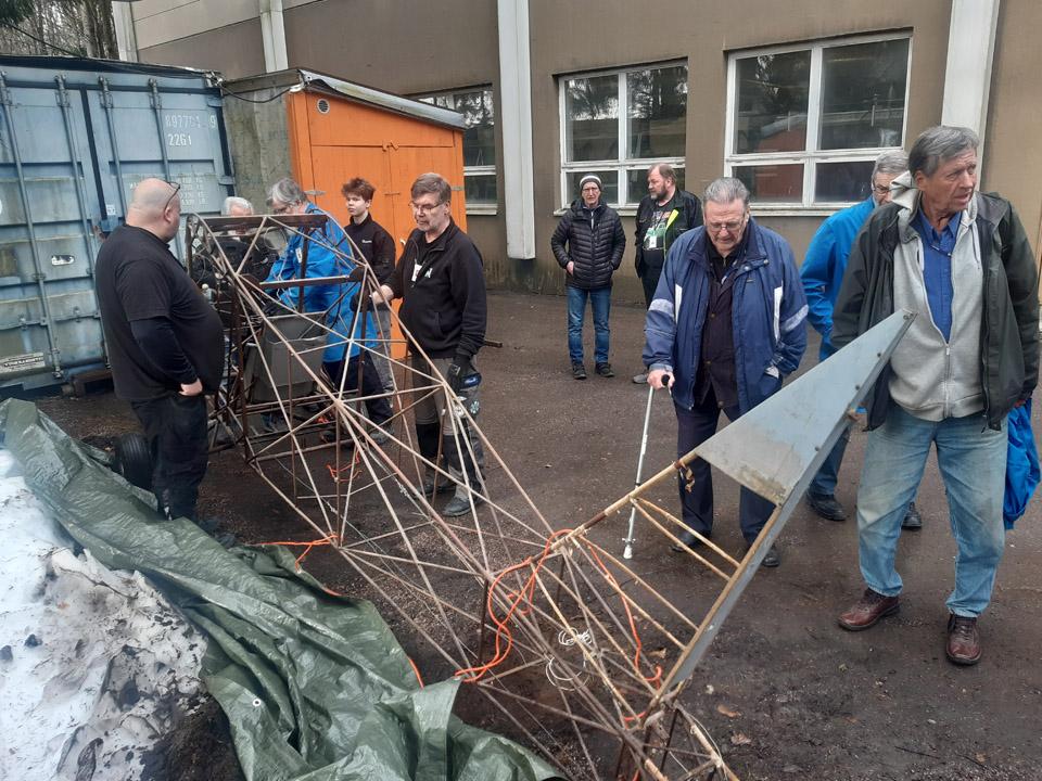
It was time to head back to Vantaa and the Finnish Aviation Museum, where we arrived late in the afternoon. On the museum yard we unfastened the cargo straps from Ressu’s fuselage frame and reassembled the wheels on the landing gear. Then we lifted the fuselage frame from the trailer on the asphalt-covered museum yard and pushed it on its wheels in front of the restoration workshop. As the Ressu’s fuselage frame will remain outside for the time being, we wrapped a tarpaulin around it to protect it from rain.
The Ressu’s fuselage frame is now ready to face the restoration procedure of the Tuesday Club. The first actual work item will be to clean the rusty frame tubes of the fuselage frame, stripped of its fabric covering. Then the tubes will be painted with protective Isotrol paint. Photos by Lassi Karivalo except if otherwise mentioned. Translation by Erja Reinikainen. |
|
Avainsanat: aviation history, restoration, Tuesday Club, Hietanen HEA-23b, OH-XEA, "Ressu" |
The Caravelle right-hand wingtip leading edge is completedKeskiviikko 27.3.2024 - Tuesday Club member Owned by Aviation Museum Society Finland and now on display at Turku Airport, the Caravelle lll (OH-LEA Sinilintu, Bluebird) has had its damaged right-hand wingtip leading edge restoration completed. The wingtip in the Caravelle is a separate entity, which can be detached from the wing. For the sake of simplicity, I’ll use the term wingtip for this structure in the future.
The last task in building the new leading edge for the wingtip was to rivet the edges of the upper and lower covering sheets to the centre line of the leading edge. The edges of the covering sheets meet at the centreline of the leading edge. Otherwise the covering sheets of the new wingtip had already been riveted in the wingtip structure.
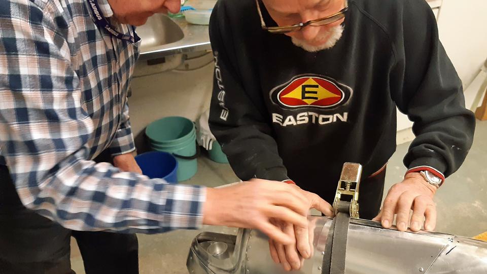
To be able to rivet the covering sheet edges on the leading edge centreline, the sheet edges were tightened against the leading edge using a cargo strap, tied around the wingtip. After this, rivet holes were drilled at both ends of the sheets and the edges were riveted on the centre line with pop rivets.
It was noticed that a gap of 1-4 mm was left between the edges. The edges of the sheets therefore didn’t reach each other to form a butt joint. It was decided to cover the gap with an aluminium covering strip, running along the leading edge centre line.
To make the covering strip, an 8 cm wide and 40 cm long aluminium strip was cut out of 1 mm thick aluminium sheet to conceal the seam between the covering sheets. The aluminium strip was shaped to the curved form of the leading edge by shaping it against a suitable size iron tube. The concealing strip was arduous to shape because the wingtip leading edge slopes to various directions. The strip was, therefore, moulded phase by phase, fitting it to place at times. Thus the concealing strip was made to press tightly against the leading edge ridge.
Now the blue plastic films protecting the aluminium sheet could be removed and start the riveting of the covering strip. For the riveting the covering strip was tightened to place at both ends with a cargo strap. Masking tape was applied to both ends of the covering strip to mark the places of the pop rivets. The places were marked on the surface of the tape at even spaces with a compass and pencil, and the holes for the rivets were drilled accordingly.
We discussed what would be the best order to rivet the covering strip, so that it would best confirm to the shape of the wingtip leading edge. We ended up in starting the riveting from the rear end of the covering strip, proceeding rivet by rivet towards the wingtip. In doing so, the covering strip riveted itself tightly to the wingtip leading edge. Finally, the edges of the covering strip were tapped with a hammer and a piece of wood to press it still more tightly to the underlying surface of the covering material.
The demanding task of rebuilding the destroyed wingtip leading edge of the Caravelle III was now ready. Let’s not forget the fitting of the 3D-printed navigation lamp cover to its place in the leading edge tip. Photos by Lassi Karivalo. Translation by Matti Liuskallio. |
|
Avainsanat: aviation history, restoration, Caravelle, OH-LEA, Sinilintu, Bluebird, Tuesday Club |
Covering the Link Trainer aileronsMaanantai 18.3.2024 - Tuesday Club member The wing refurbishing of the South-Karelian Aviation Museum’s Link Trainer has moved on to the covering stage. At first we set on to covering the ailerons. One aileron was original and the other built at the Aviation Museum Society’s Tuesday Club to replace the missing aileron. Stripped of its covering, the repaired original aileron and the rebuilt aileron were covered with a special cotton fabric for covering, bought from Switzerland at Craftlab.
The covering was commenced by setting the aileron on the covering fabric and drawing the shape of the aileron on the fabric with a felt pen. The fabric was cut with a wide margin, taking into consideration the actual space for working. The fabric was folded around the aileron, so that the lapels met at the trailing edge. The lapels were fastened together with wig pins, at the same time tightening the fabric on the aileron. T-headed and long wig pins are very handy for this purpose. The pins were acquired from a Chinese on-line shop.
After the lapels of the covering fabric had been fastened to each other with pins, we were facing with tightening the fabric with water. Water tightening is the first phase to make the covering fabric tight. In the process the warp and weft already shrink somewhat, i.e. the fabric pre-tightens around the aileron. For water tightening the water was boiled. By boiling the water it will be disinfected, so that organic impurities won’t infect the fabric, which could cause the fabric to mould. Well, in this case the boiling wouldn’t have been necessary, because we aren’t dealing here with an airworthy device. After the water had cooled down, the fabric was thoroughly soaked.
After the fabric had dried, the proper tightening was commenced. It will be done with nitrocellulose lacquer, which causes the fabric to become as tight as a drumhead. As a lacquer we used NC-Speed nitrocellulose lacquer and as thinner Ohenne 8. Red iron oxide was mixed into the tightening lacquer as a pigment. It is customary to colour the tightening lacquer, so that you can keep track of which areas have been dealt with and which haven’t.
25 % lacquer.
50 % lacquer. The tightening coats of lacquer for the covering fabric will be applied in phases by starting with diluted lacquer and ending up with undiluted lacquer. The Link Trainer’s ailerons were applied at first with two layers of 25% lacquer, followed by two applications of 50% lacquer, one application of 75% lacquer and to finish it all an application of undiluted nitrocellulose lacquer. The lacquered surfaces were sanded between applications for the fuzz, which was stood up by the lacquer.
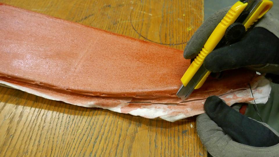
After the application of 50% lacquer, the fastening pins of the covering fabric were removed. At the same time the extra fabric lapels’ surplus to the trailing edge were cut off with a Stanley knife. This was possible, because the covering fabric was glued firmly enough to the trailing edge of the aileron, the ribs, and other parts of the aileron structure. The trailing edge will be sanded smooth, and a serrated cotton strip will be glued to it to strengthen it.
75 % lacquer. In this connection it must be noted that in case of an airworthy aircraft, the covering fabric would have been sewn to the ribs of the aileron, the same way as the fabric would have been sewn to the wing ribs. In not covering the ailerons and the wings we decided to cut corners, so in this case skip sewing the fabric to the ribs. This had been the case with the damaged covering fabric we stripped off the wings.
The tightening lacquer for one aileron is ready and waiting for to be painted beige. The other aileron will receive a few more applications of lacquer, before its fabric will be as tight as a drumhead. Photos by Lassi Karivalo. Translation by Matti Liuskallio. |
|
Avainsanat: aviation history, restoration, Tuesday Club, Link Trainer |
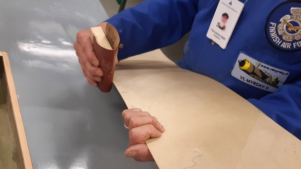
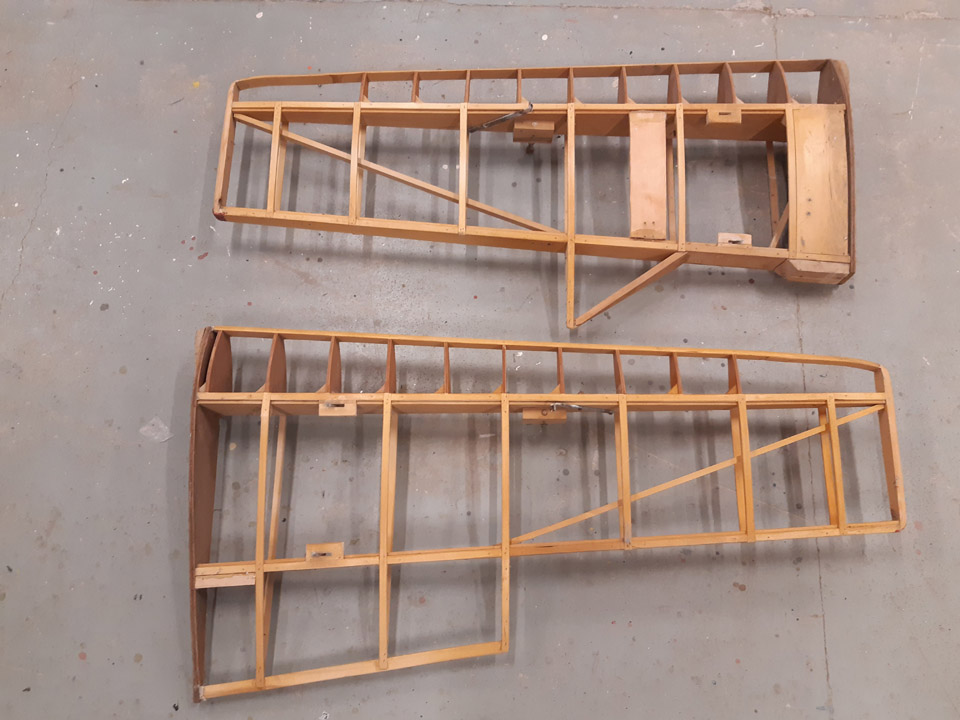
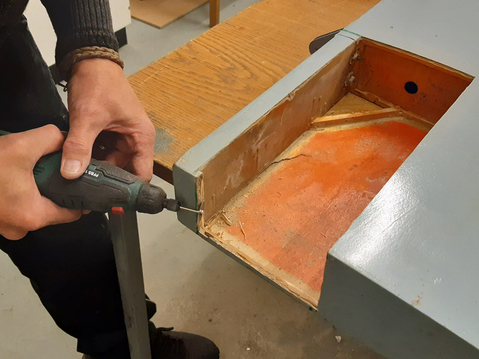
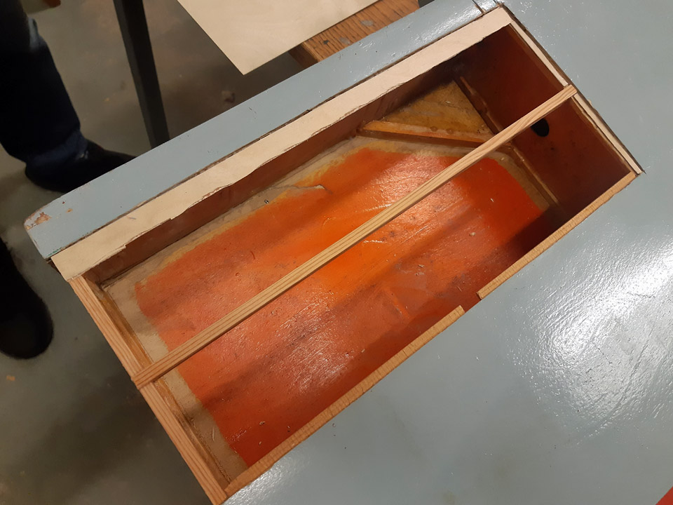
Damages in the Ressu (Snoopy) plywood covering repairedTiistai 12.3.2024 - Tuesday Club member The restoration of the experimental aircraft (OH-XEA) “Ressu” has so far concentrated on the work with repairing the holes and damages in the plywood covering of the wing halves, ailerons, horizontal stabilizer, and the elevator. This job has now been finished as far as patching goes.
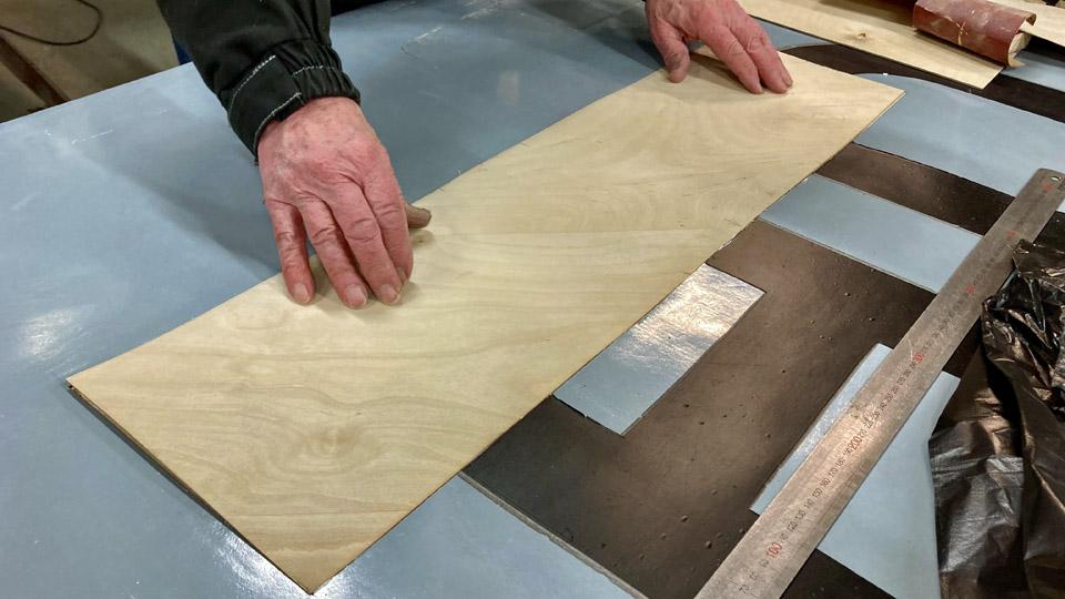
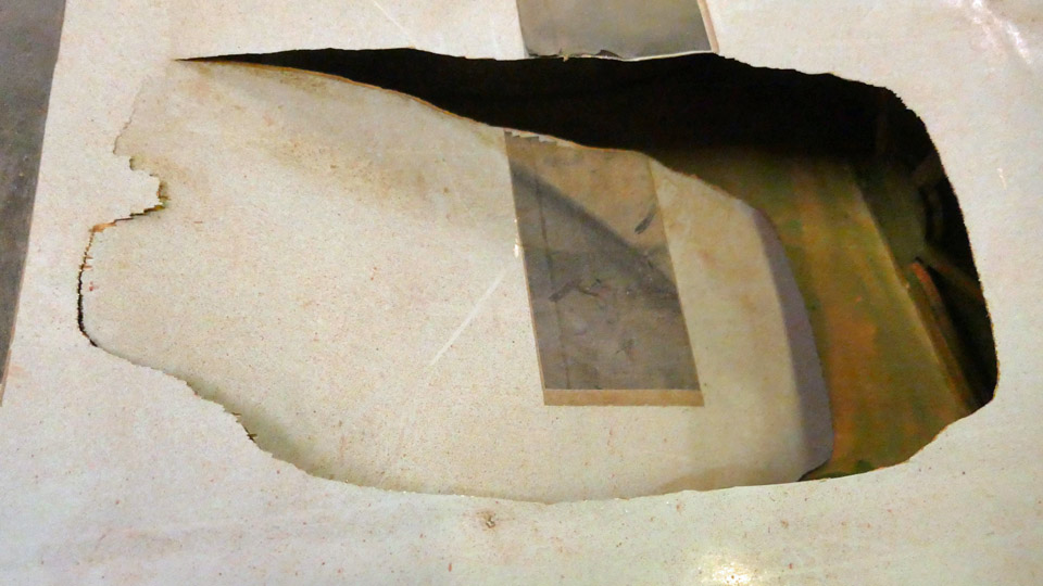
There were about twenty holes and damaged areas in the plywood covering. Part of them being tiny pinpricks, but some were damages measuring tens of centimetres. As patching material, 0,9 mm aircraft plywood was used. To patch small holes, Ressu’s original plywood with a coating of paint was used. We obtained it in connection with clearing the large damaged areas in the wing. In patching the holes in the Ressu plywood covering, we followed the same proven method throughout. In this blog the patching of a largish damage on the lower surface of the left-hand wing will be presented as an example.
A hole, or an area of a larger damage, was sawn open to a square or rectangular shape. In sawing, a “Kugihiki”, or a so-called Japanese saw was used, which is an excellent tool for sawing thin plywood. Supporting battens were glued under the sawn edges, so that about 1 cm protruded from the inside of the opening. The plywood patch to cover the opening will be glued on these supporting battens.
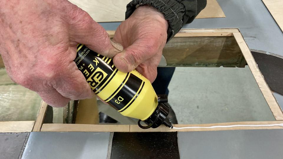
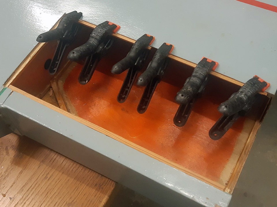
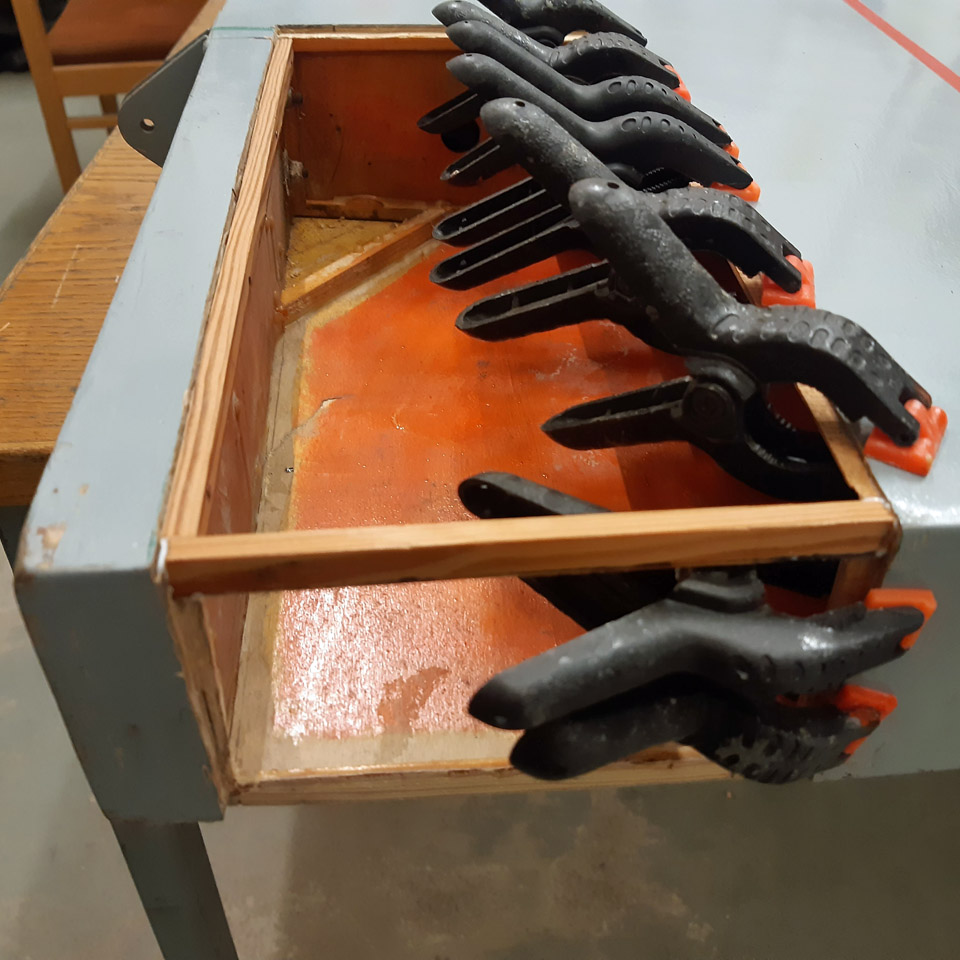
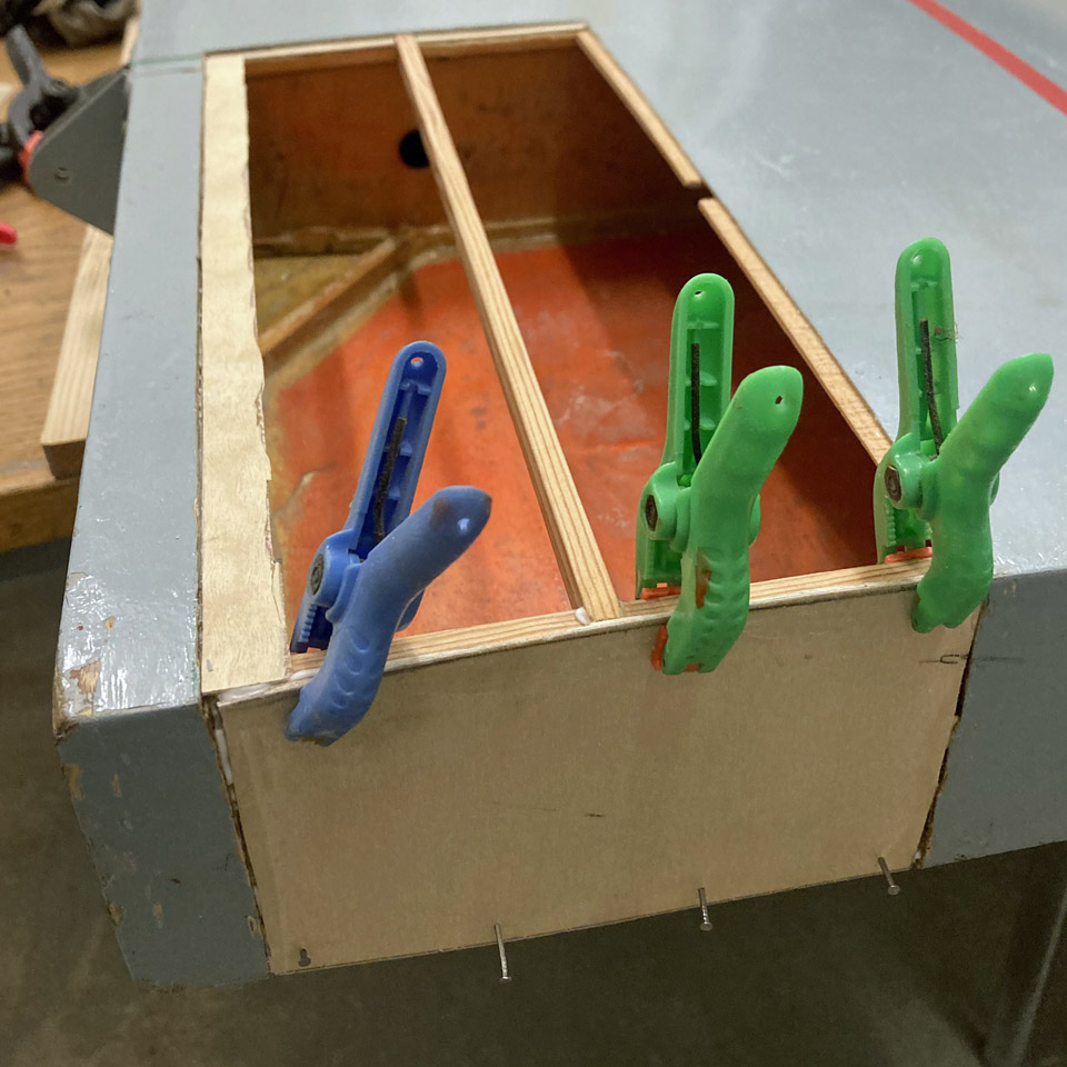
For gluing the supporting battens and the plywood patches, moisture resistant Erikeeper Plus or Casco Outdoor glue for wood was used. Before gluing the support battens, the protective lacquer was ground off the edges of the underside of the covering plywood. Thus the glue sticks better on the underside of the covering plywood. The support battens were pressed onto the edges of the underside covering plywood with small clamps. Work was also in progress with other holes in the wings, simultaneously with this large opening underside the left-hand side wing.
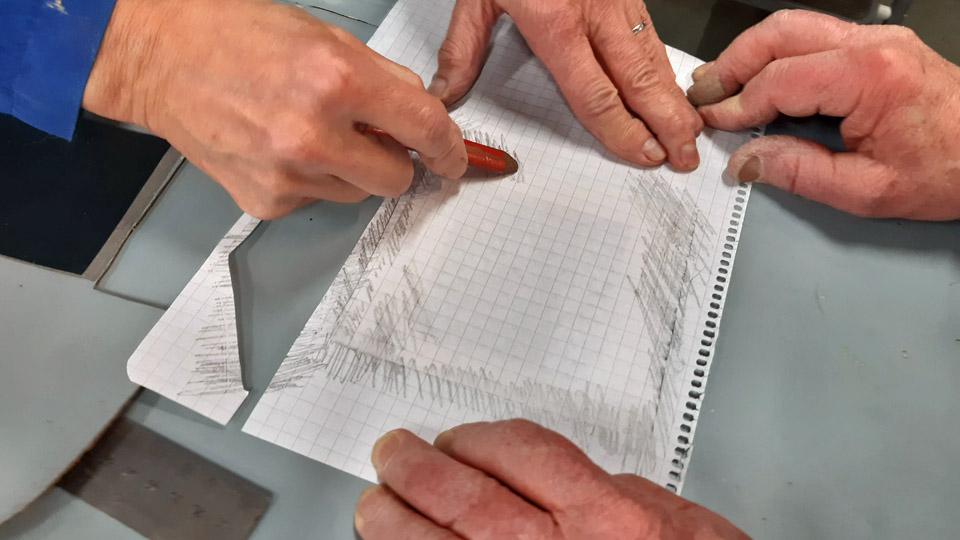
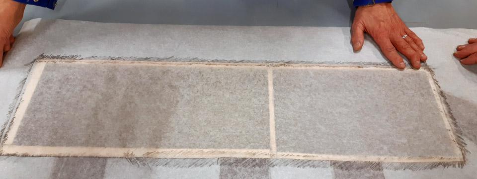
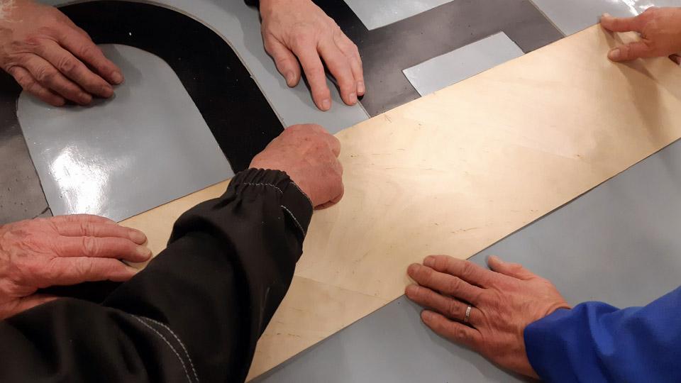
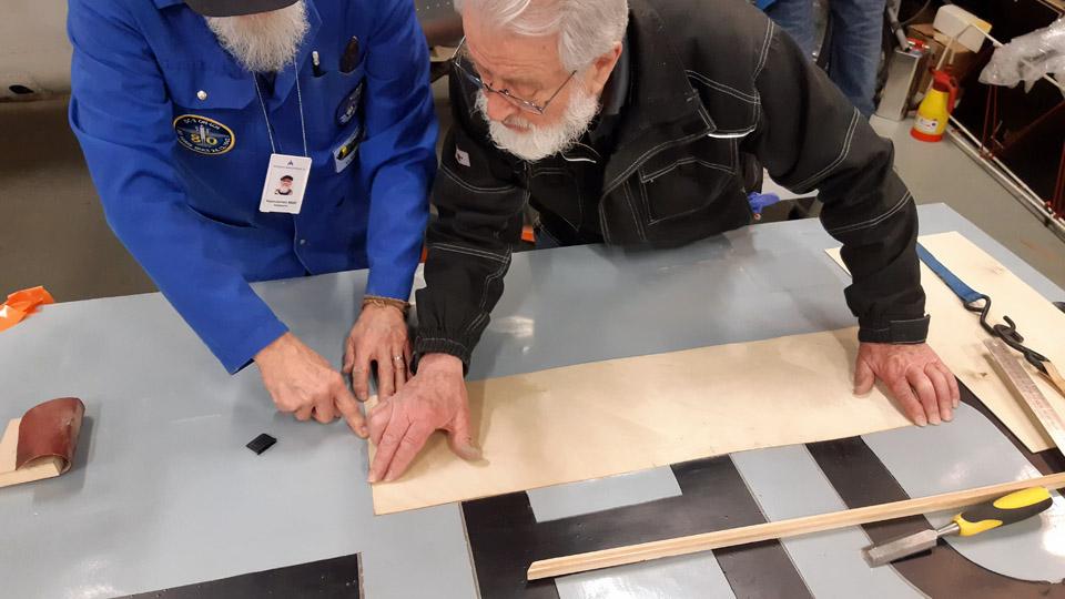
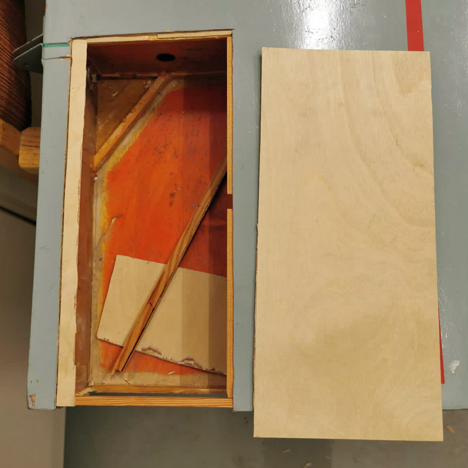
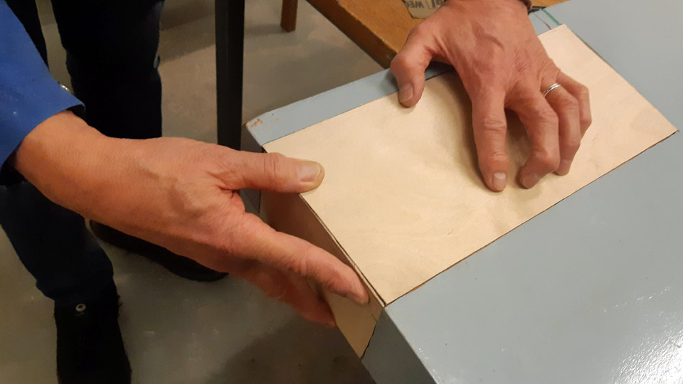
After the glue had dried, a sheet of thin paper was fastened over the whole opening to be patched. The plywood edges of the plywood opening were “smudged” with a pencil so that it became visible on the paper, thus producing an image of the edge line of the opening. The paper was cut along the now visible opening edge in the plywood. So we had a model to cut the right size of a patch. The paper was superimposed on a sheet of plywood and, hey presto, after this model a plywood patch we needed was cut out of the sheet.
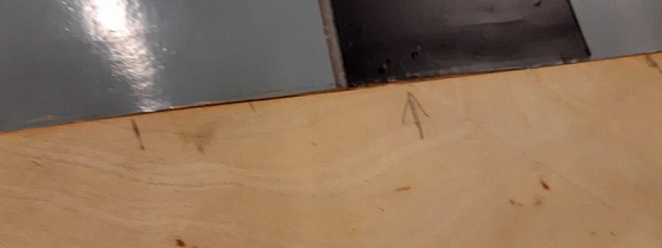
The cutout piece of plywood was fitted in place on the support battens. We marked with arrows the places where the plywood patch still needed filing at the edges, to get the patch press itself in a butt-joint manner against the edges of the opening. When the plywood was in place, glue was spread on the support battens, and the plywood was pressed against the battens.
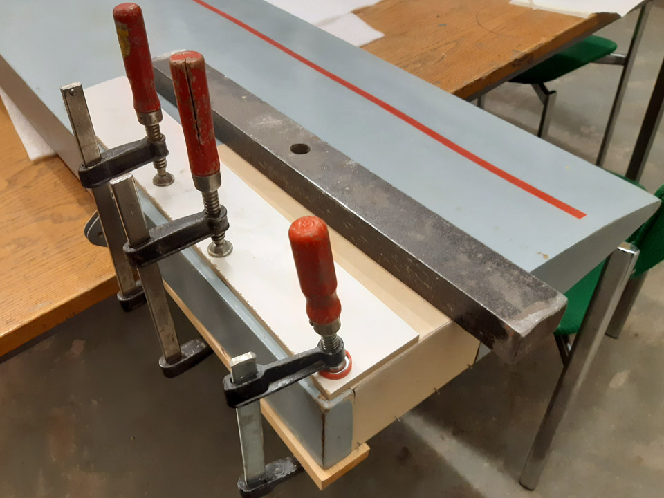
The gluing of the plywood patch was secured by putting a sturdy plywood sheet on the patch and iron weights piled on it. At the lowest a sheet of foam rubber was placed to distribute the weight evenly.
Before laying the weights, a layer of protective plastic was spread over the patch, to prevent extra glue from seeping off the seams of the plywood patch and possibly sticking to the foam rubber sheet. When both the foam rubber sheet and the sturdy plywood sheet were in place, iron weights were piled on the plywood sheet. We noticed after the glue had dried and the weights and the plywood sheet were removed, that the plywood patch had settled very neatly in place. Photos by Lassi Karivalo. Translation by Matti Liuskallio. |
|
Avainsanat: aviation history, restoration, Tuesday Club, Hietanen HEA-23b, OH-XEA, "Ressu" |
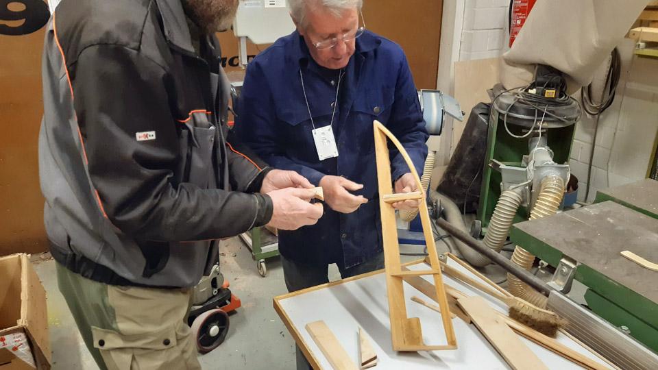
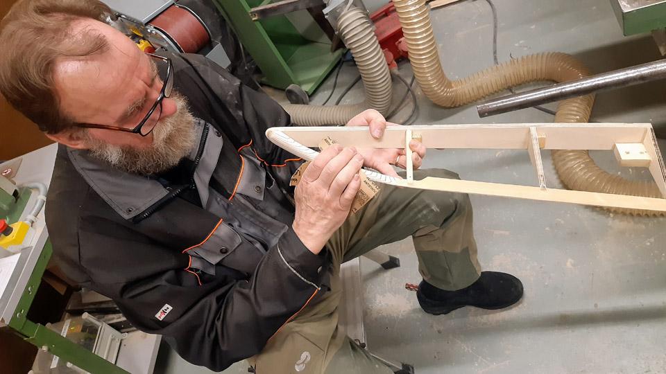
Building of the missing Link Trainer aileronSunnuntai 10.3.2024 - Tuesday Club member The restoration of the Lappeenranta based Karelian Aviation Museum’s Link Trainer wings is underway at the Aviation Museum Society’s Tuesday Club. Our main work is to refurbish the wings and cover them again. Furthermore the missing aileron from the left-hand wing had to be built. As a model we used the right-hand wing aileron, which was stripped of its covering.
Photo by Kimmo Marttinen.
Photo by Lassi Karivalo.
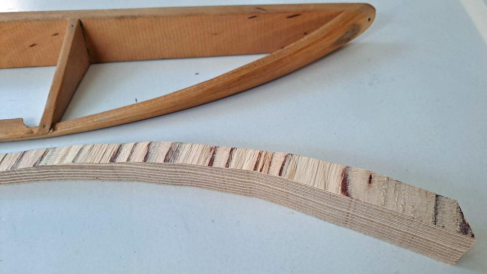
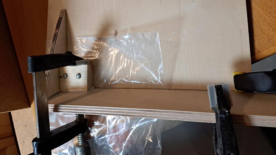
Photo by Lassi Karivalo. We started to build the aileron from strips of wood according to the original. However, we noticed after a few days that the finished parts of the aileron didn’t keep their form, but there were distortions. The material we used wasn’t good enough. We ended up with a solution different from the original by building the left-hand aileron mainly from plywood, which keeps its form well. The decision facilitated our work also so that the curved trailing edge tip had originally got its form from strips of wood soaked in water. Making the curved part of the aileron from plywood will be easier.
Photo by Lassi Karivalo.
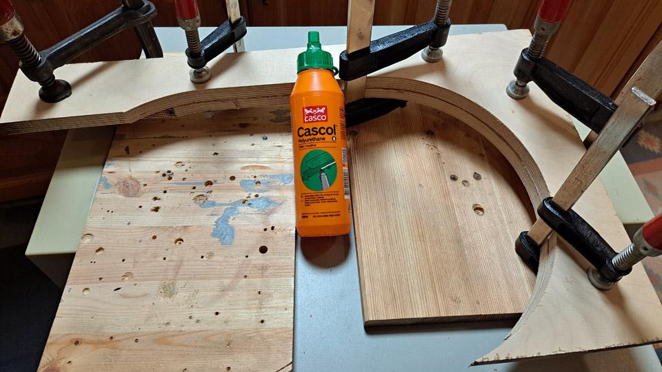
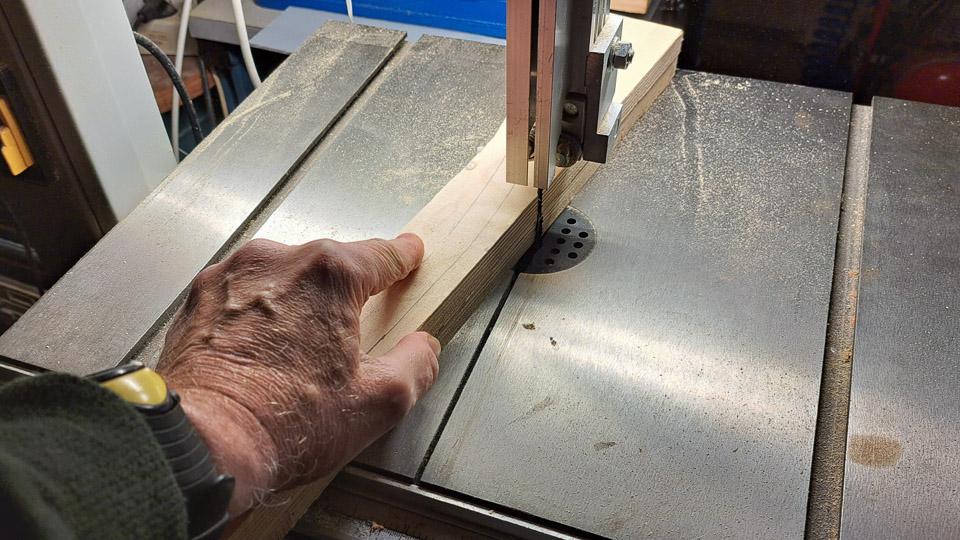
We started making the aileron from the curved tip of the trailing edge. In order to get thick enough plywood to build the trailing edge tip, we glued two sheets of plywood together. After the glue had dried, a picture of the right-hand aileron’s curved trailing edge was drawn on the plywood. The plywood was sawn along the drawing line, to give us a blank for the left-hand aileron trailing edge. The blank was shaped tentatively to its form.
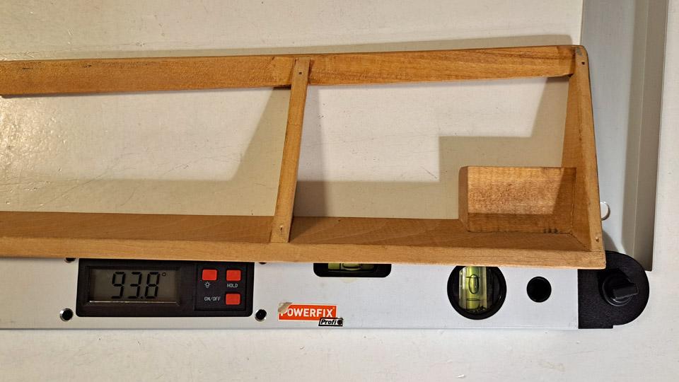
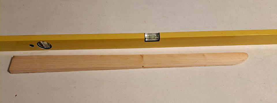
Next we made from plywood the left-hand aileron’s leading edge, which could be called the spar of the aileron. We sawed it from 6 mm thick plywood according to the model given by the right-hand aileron. The leading edge is not at right angles to the wing base. The correct angle (98,3 degrees) was defined from right-hand aileron’s leading edge. The left-hand aileron’s leading edge base was ground to that angle. The leading edge batten was now ready.
The necessary three triangular ribs were made of plywood according to the right-hand wing aileron ribs and angles. In the same way some thin 3 mm strip of pine was found, from which the straight stem of the trailing edge was made. The trailing edge stem will be joined according to the original model with a 5 cm long glue joint to the curved tip of the trailing edge batten.
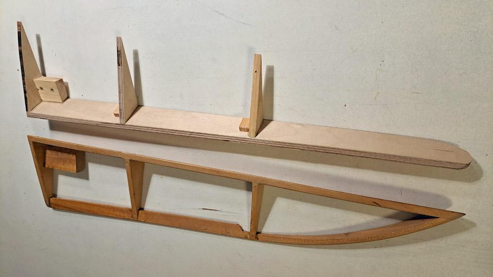
When all the components of the aileron had been made, the construction of the aileron was started. The compilation was commenced with the leading edge and the ribs that were glued to it. As a gluing platform sturdy plywood was used, onto which a guiding piece with an angle of 93,8 was fastened. The leading edge batten was fastened with clamps to the guide piece and its sturdy platform. First the aileron’s root rib was glued into place and after that the two other ribs. The gluing was secured with two screws. The aileron had already got its basic form.
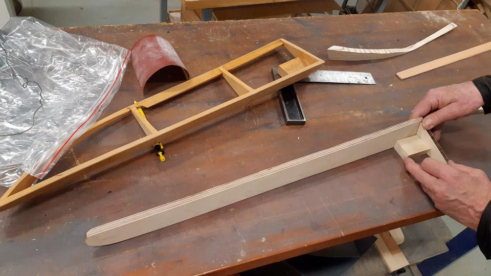
The trailing edge of the aileron was still missing. First the straight thin stem of the trailing edge, which was shaped from a batten of wood, was glued to the ribs. Last to go to place was the curved tip of the trailing edge. At the same time the tip and stem were joined at the rib with a glue joint. The rib also strengthens the glue joint. Because the curved tip of the trailing edge had only been tentatively ground, the tip was ground to final form after the glue had dried.
The missing aileron of the Link Trainer was structurally finished. The aileron will be covered and painted in accordance with the covering of the Link Trainer wings. Photos by Pauli Jokimies except if otherwise mentioned. Translation by Matti Liuskallio. |
|
Avainsanat: aviation history, restoration, Tuesday Club, Link Trainer |
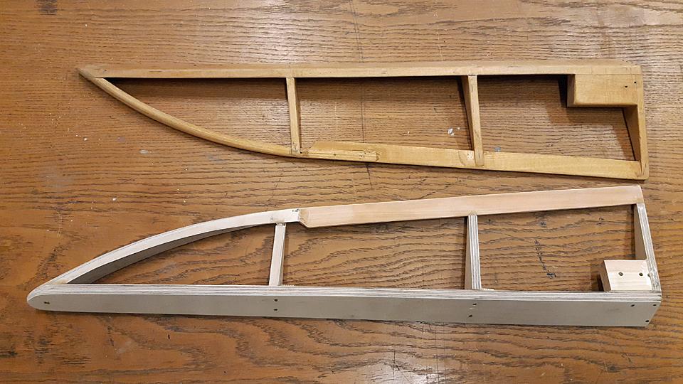
Restoration of the Ressu (Snoopy) experimental aircraft?s wing struts and building the missing oneLauantai 17.2.2024 - Tuesday Club member The restoration of the Ressu aircraft’s wing struts is completed. The aircraft was designed and built by the brothers Hietanen from Turku in the 1960s. Originally registered OH-HEA, the aircraft was registered as an experimental aircraft with the registration OH-XEA in 1969.
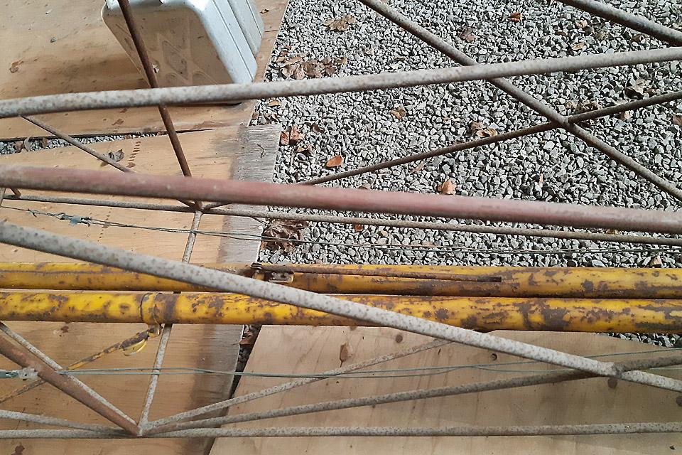
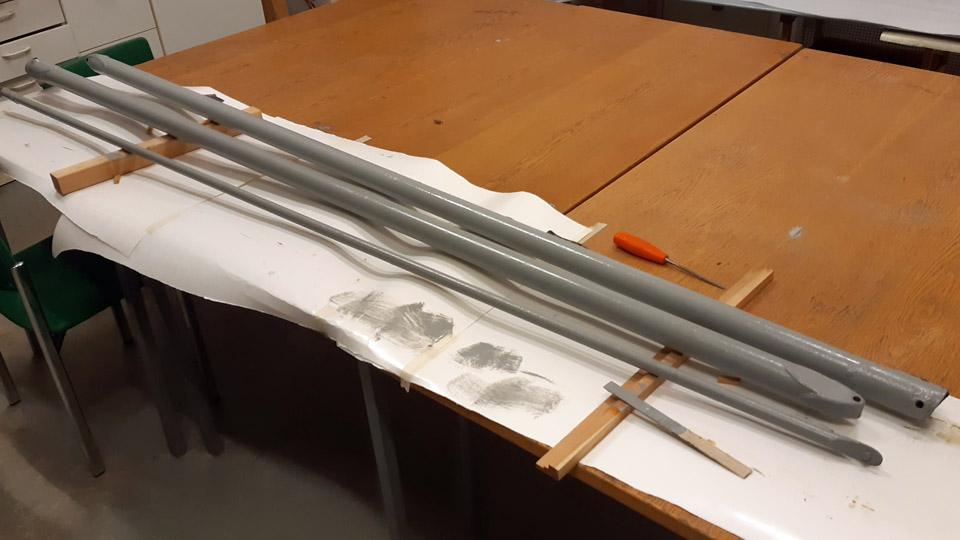
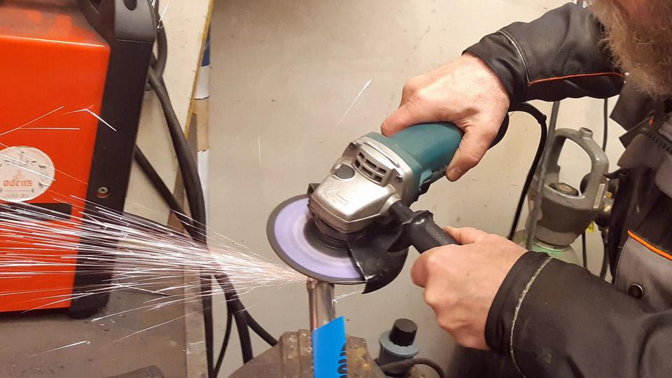
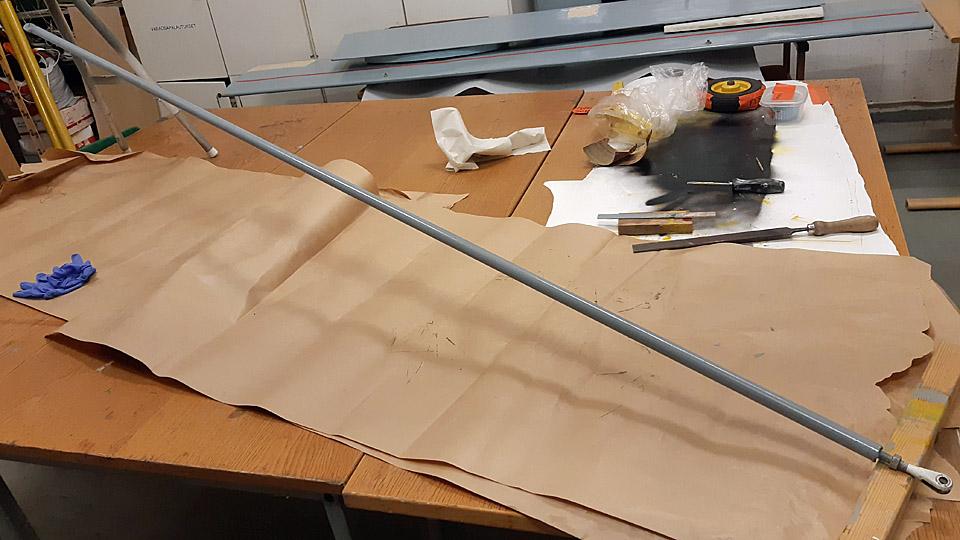
The wing halves of the high-wing Ressu are supported with two wing struts fastened to the fuselage lower edge. The front strut has been made of 50 mm and the rear strut of 20 mm thick steel tube. Both the front struts have remained, but only one of the rear struts. These three struts had been in storage inside the bare fuselage frame, which had no covering. The rusty struts were restored yellow according to the original paint scheme and the missing strut was built.
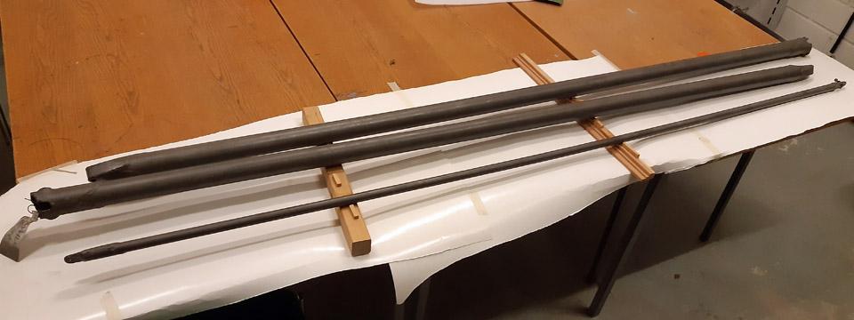
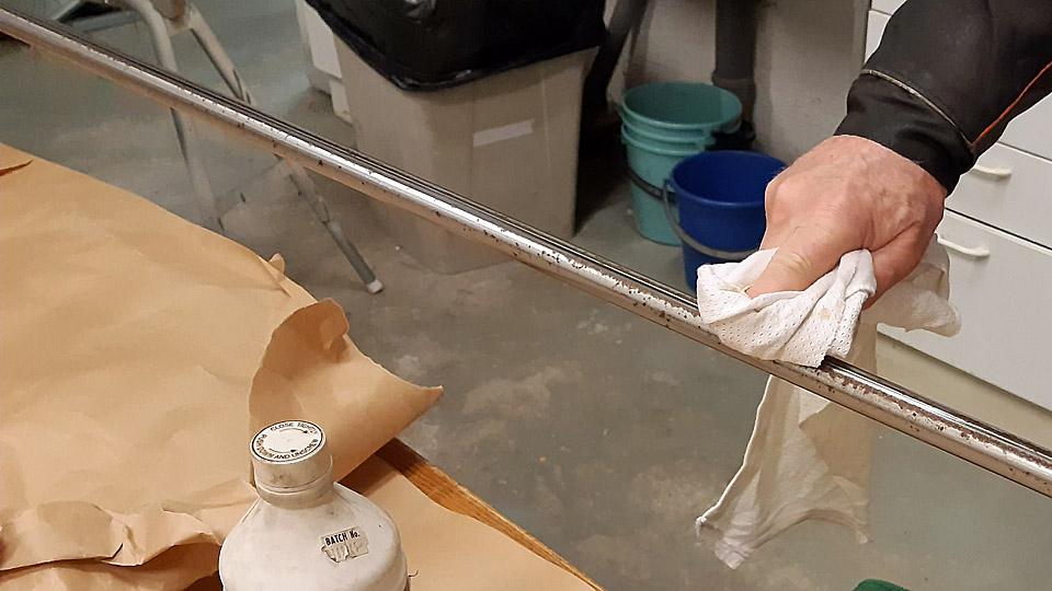
The restoration of the struts was started by taking them to be sand blasted at Taximo Oy in the Tattarisuo area in Helsinki. The sandblasted struts were dealt with a transparent anti-rust Isotrol-lacquer immediately after the sandblasting. The struts were primed with light grey Isotrol-paint of the shade RAL 7005. The light grey primer worked well for the yellow finishing paint of the struts.
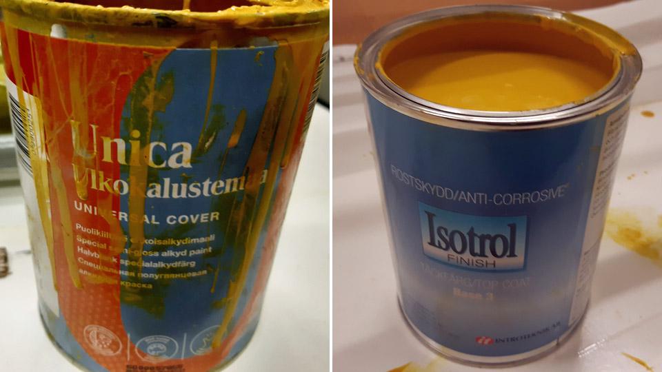
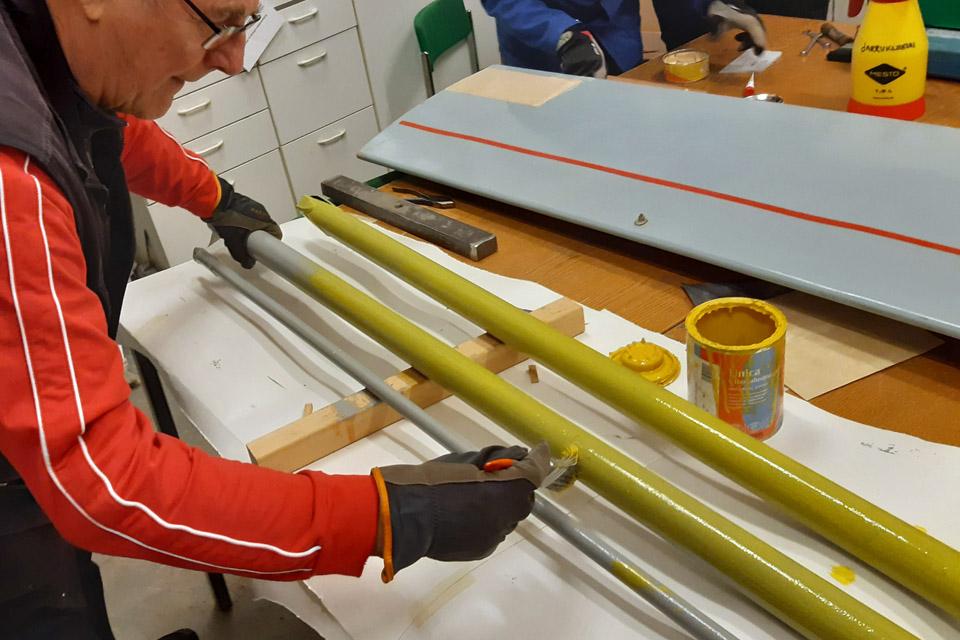
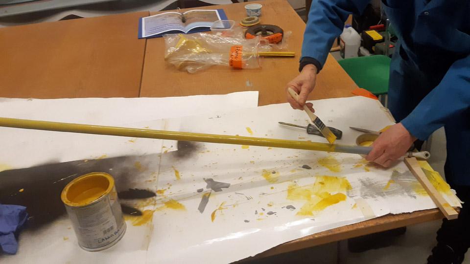
As the yellow finishing paint we used at first the Tikkurila UNICA outdoor furniture paint with RAL 1023 as the shade. The yellow paint had poor coverage, which we knew in advance. To replace the UNICA, a corresponding yellow Isotrol paint of the similar shade was chosen for the second coat of paint. The yellow pigment of the Isotrol paint has a better coverage, which was noted when painting the struts. They were painted with the yellow Isotrol three times over, so
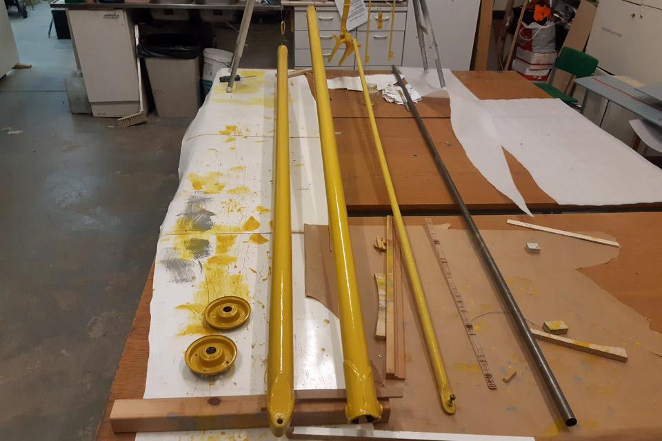
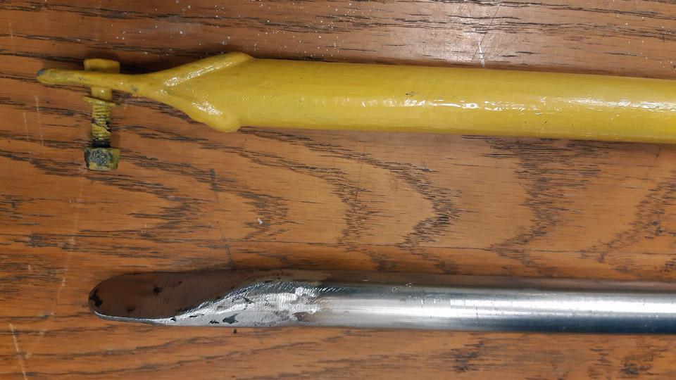
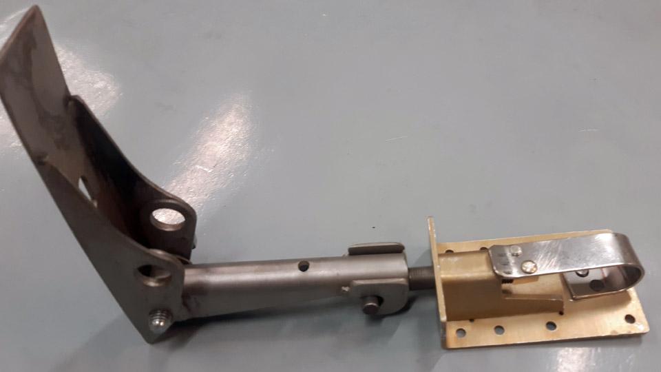
To make the missing rear strut, a 2,5 m long 22 mm thick steel tube was bought from Starkki hardware store. As a model for the building, a wing rear strut has survived. At both ends of the rear strut there’s a fixed bracket plate, with holes in it to fasten the strut to a bracket in the wing and the fuselage.
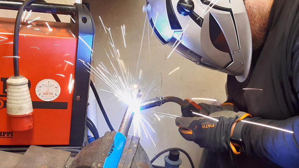
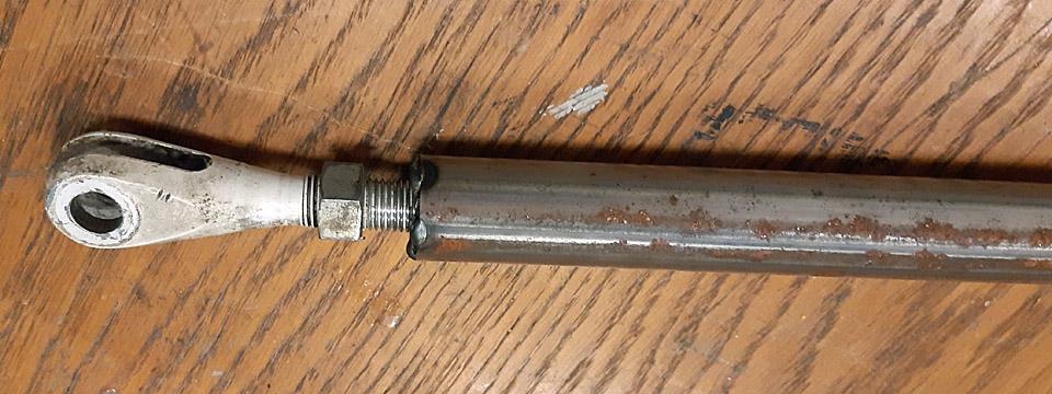
When we examined the photographs of Ressu at our disposal, we noticed that the lower end of the rear strut had been adjustable and not fixed, as was the case with the rear strut at our disposal. At the lower end of the strut can be seen a fork-like bracket with a threaded spindle. It was evident that the lower end of the rear strut had been changed to a fixed bracket. We decided to make the missing rear strut lower end adjustable, to correspond to the wing strut in the photograph. For this purpose we received a wing strut adjustable head used in a Super Cub.
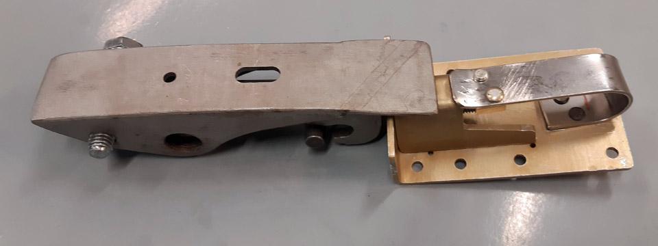
The building of the missing wing rear strut was started by cutting the steel tube to the measure of the rear strut. First we made the lower end of the rear strut. We welded a suitable nut, which fitted the threaded spindle of the lower end of the tube and screwed the bracket in place.
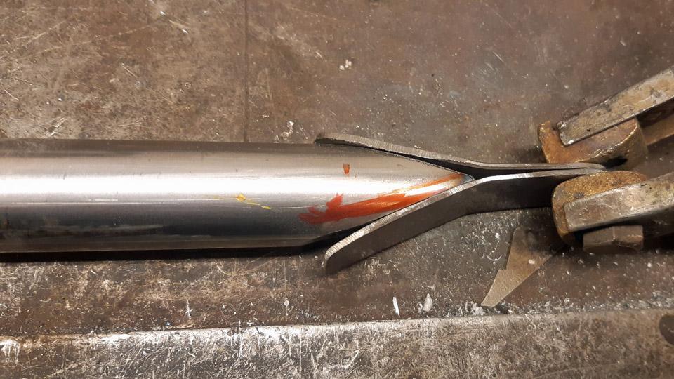
We made the wing rear strut top end a fixed one, according to the strut we had at our disposal. The end of the tube was sawn at an acute angle. After that the bracket halves for both sides were cut out of 2 mm metal plate to be welded in place. They were welded to the top sides of the tube. After welding, the bracket was ground to its final shape. When a hole had been drilled for the strut fastening bolt, the new strut was structurally finished.
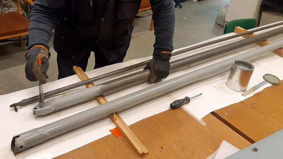
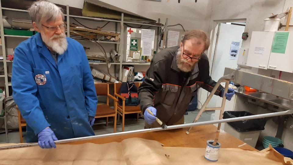
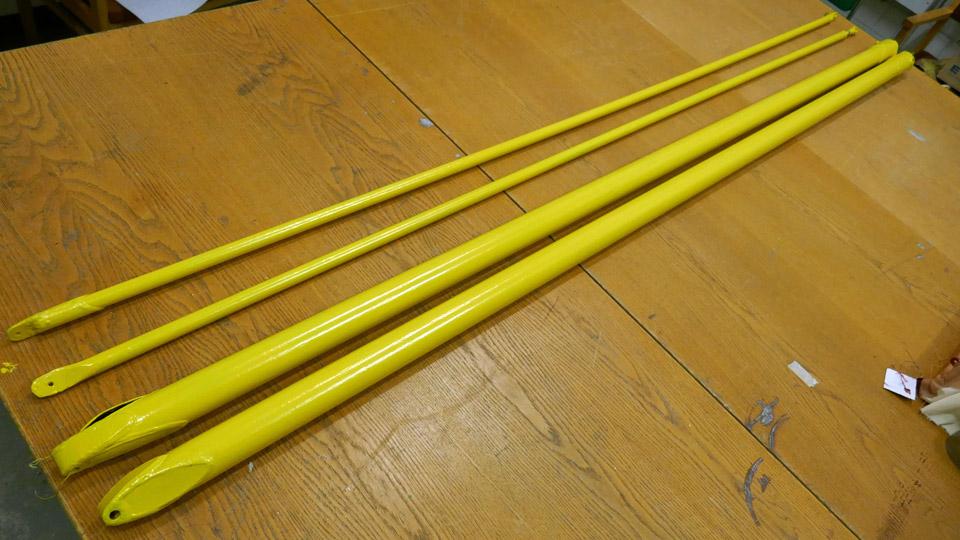
The new wing strut was primed with light grey Isotrol paint, the same way as the three original ones had earlier been dealt with. After the primer had dried it received a coat of yellow Isotrol paint. Thus we had restored the two original front wing struts and a rear strut of the Ressu-aircraft and built the missing wing rear strut Photos by Lassi Karivalo. Translation by Matti Liuskallio. |
|
Avainsanat: aviation history, restoration, Tuesday Club, Hietanen HEA-23b, OH-XEA, "Ressu" |
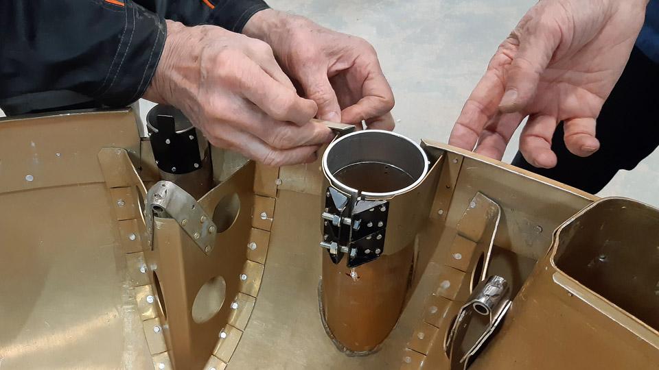
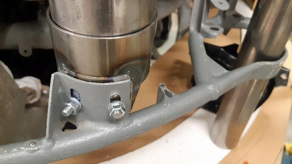
The Myrsky engine NACA-ring and lower cowling completionKeskiviikko 7.2.2024 - Tuesday Club member The engine’s NACA-ring of the VL Myrsky II (MY-14) under restoration was completed when the tightening collars, made at the Tuesday Club for the four machine gun flash tube openings at the upper part of the NACA-ring, were fitted. With the tightening collars the flash tubes made of steel will be locked to the four openings intended for them in the NACA-ring. Of the four openings the two midmost will have 70 mm flash tubes and the lateral ones will have 45 mm flash tubes. The midmost flash tubes will be fastened at their rear end to brackets on the ring of the engine cradle. The machine gun barrel will thrust itself into the rear end of the lateral flash tube, holding it in place.
The excessively long flash tubes are still “sticking out” of the NACA-ring flash tube openings. They will be cut shorter, so that the flash tube ends will only protrude to some extent out of the flash tube openings. The difference in sizes of the flash tubes is due among other things to the fact that there’s no room at the side of the engine under the upper cowling for thick flash tubes. There are shields as well made of steel plate above these narrow flash tubes. They protect the upper cowling, which is nearly touching the flash tube, from overheating when the machine gun is firing. But all the same, both sizes of the flash tubes serve the four 12,7 mm LKk/42 machine guns.
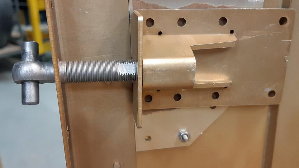
Building of the lower cowling is almost completed at the Tuesday Club. The last tasks have been the guides, which will be fastened on the cowling’s inside surface stiffening strip, the guiding pegs to the front end of the cowling, and the tightening latches, with which the lower cowling will be locked to the upper cowling. Let it be pointed out, that the MY-14 engine upper cowling will be built in the Finnish Air Force Museum.
The guides, as well as the guiding pegs, and the tightening latches were made at the Tuesday Club. Owing to the guides and the guiding pegs, the lower cowling is easy to fit into place. Three slot-formed guides were riveted on the cowling’s inner surface rearmost stiffening strip. With the aid of these slot-formed guides the cowling “snaps” in place to the fastening ring of the rear part of the engine.
Photo by Jorma Laakkonen. The three guide pegs of the cowling’s front edge were riveted on the inner surface of the cowling’s front edge. The guide pegs of the front edge push into the holes drilled in the NACA-ring hem, thus fastening the cowling from its front edge on the NACA-ring. An insulation strip made of fabric was glued to the hem of the NACA-ring to separate the two metal surfaces from each other.
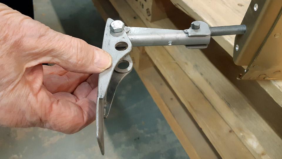
The upper and lower cowlings are locked to each other with four tightening latches. These four complicated tightening latches were built at the Tuesday Club, according to Myrsky blueprints. With adjustable tightening latches the upper and lower cowling can be locked to each other to suitable tightness. The parts of the latches with springs will be fastened to the upper edge of the lower cowling and the parts with levers to the upper cowling. The parts of the latches with springs are tentatively in place, waiting to be riveted.
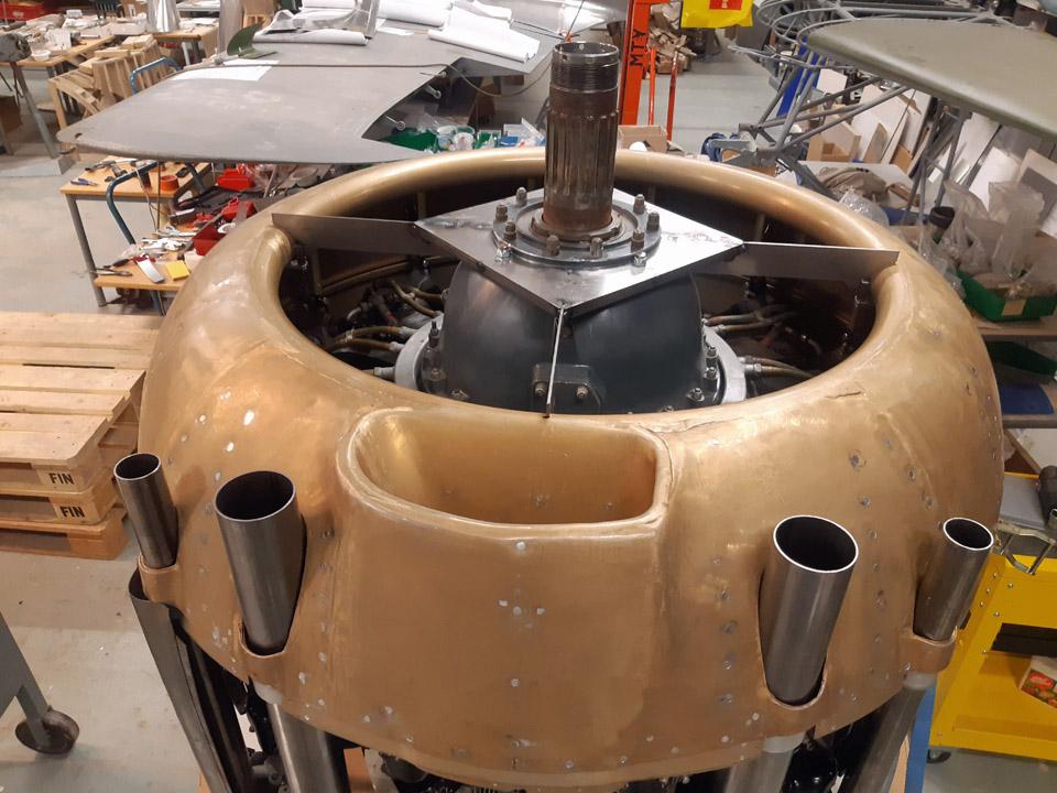
After the guides and guiding pegs had been fastened on the cowling, the cowling’s fastening to the NACA-ring was tested. The testing was done while the cowling was still fastened on the last where it was built. It was noted that the guiding pegs fitted expectedly to the holes drilled in the hem of the NACA-ring. Thus the NACA-ring was fastened in place on the Pratt & Whitney R-1830 Twin Wasp engine, after which the lower cowling was fastened from its upper edge to the NACA-ring and from its lower half to the fastening ring of the rear part of the engine. The engine is beginning to resemble that of the Myrsky fighter. Photos by Lassi Karivalo except if otherwise mentioned. Translation by Matti Liuskallio. |
|
Avainsanat: aviation history, restoration, MY-14, VL Myrsky, Tuesday Club |
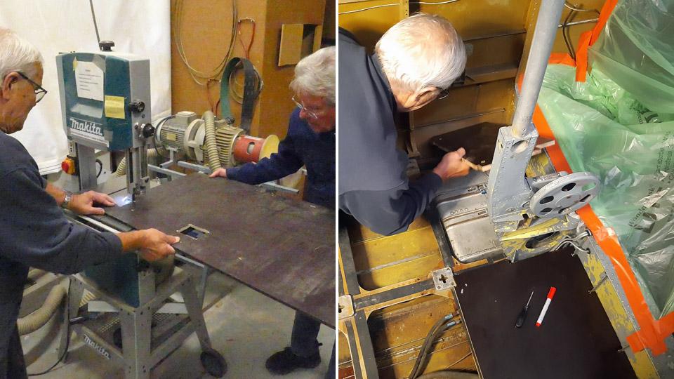
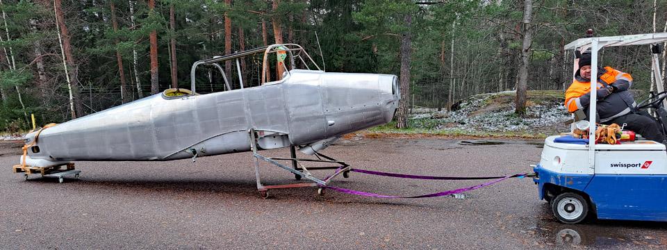
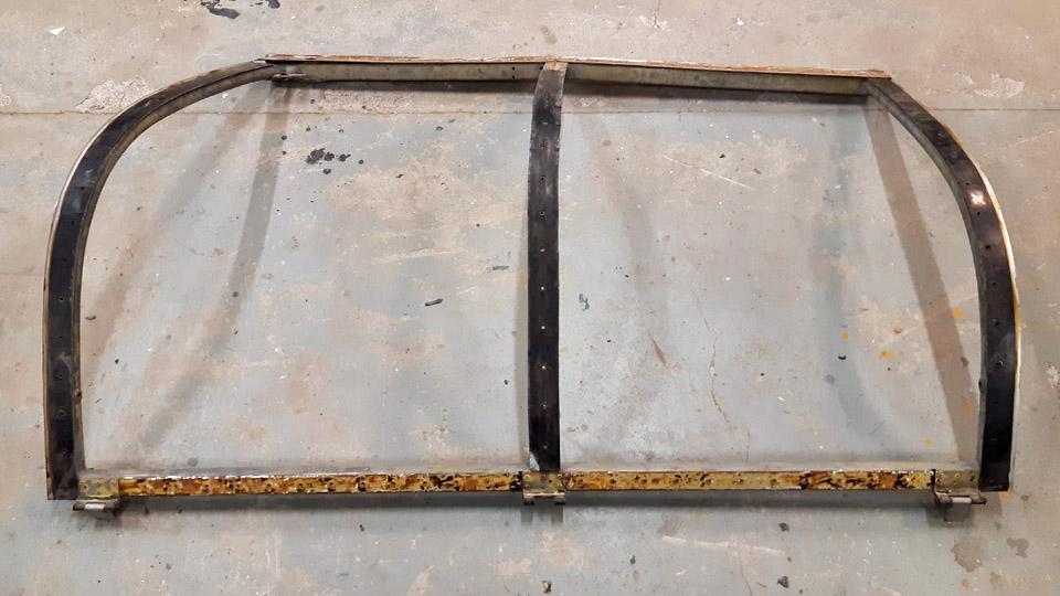
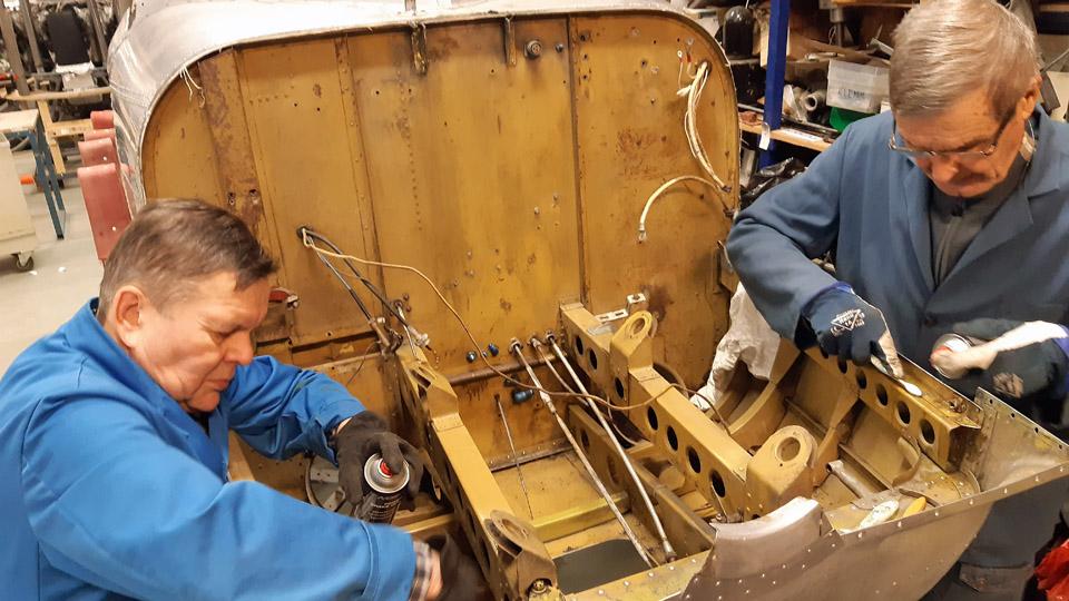
A report on the Tuuli III (TL-1) fuselage restaurationSunnuntai 28.1.2024 - Tiistaikerholainen At the beginning of the autumn season we carried on with the restoration work of the fuselage of the Tuuli III in the storage tent at the Finnish Aviation Museum’s yard. First we emptied the cockpit from the stored and packaged Tuuli parts. While doing this we noticed that the temporary cockpit floor plywood panels, that we had installed about five years ago for the period of the restoration work, were covered with mould. We disposed of them and made new ones out of 9 mm film plywood to the measurements of the original Tuuli floor panels, which were in storage. The floor panels were installed to the cockpit.
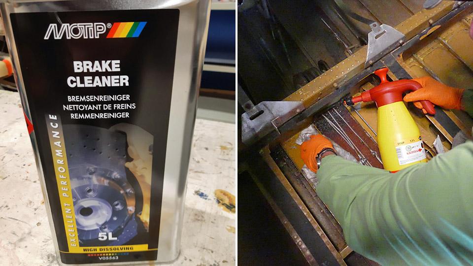
We started to clean the dirty cockpit walls and floor surfaces. We removed the surface dust with a vacuum cleaner nozzle and a brush. However, the surfaces had still to be washed clean. At first we used the steam cleaner, which had been acquired to the museum, but it turned out to be ineffective particularly in cleaning the oiled and sticky floor surfaces. The best cleaning agent for oiled and dirty surfaces proved to be a car brake cleaning liquid, Motip Brake Cleaner. The cleaning liquid was put into a spray bottle, from which the liquid was sprayed onto the surface to be cleaned and the surface was wiped clean with a rag. The cold autumn weather forced us to move indoors, so the Tuuli fuselage was towed by a lift fork from the storage tent to the Finnish Aviation Museum’s restoration workshop.
At the restoration workshop we started to work on the canopy frames, with the future glass bead blasting in mind. The completely opaque plexiglass panes had already earlier been unfastened from the frames. Our job was to strip off the sloppy rubber seals. We tried different methods for this. The best way proved to be one where we heated the seal with a hot air blower, loosening the seal simultaneously with a broad chisel. Thus we managed to get rid of the rubber seals and the frames were now waiting to be glass bead blasted and subsequent painting.
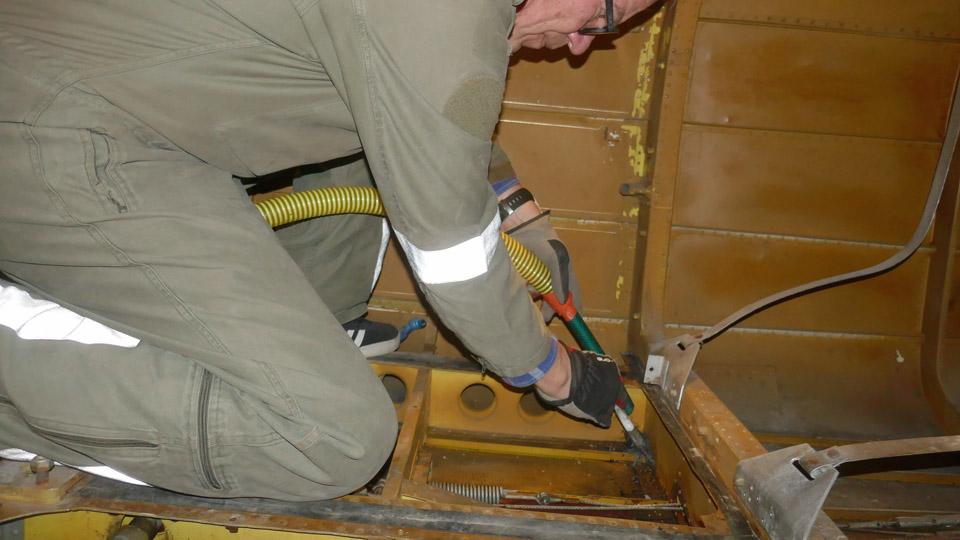
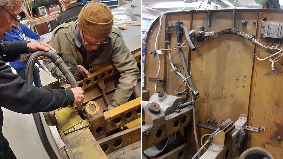
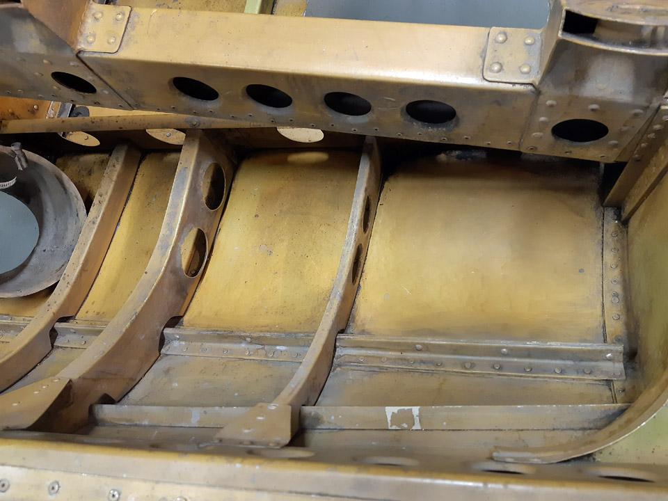
Simultaneously with working with the frames we started the cleaning of the Tuuli engine bay surfaces. For that purpose the upper engine cowling was detached. Before we could get to cleaning the surfaces, we had to dismantle wires and gadgets from the fire wall between the cockpit and the engine bay.
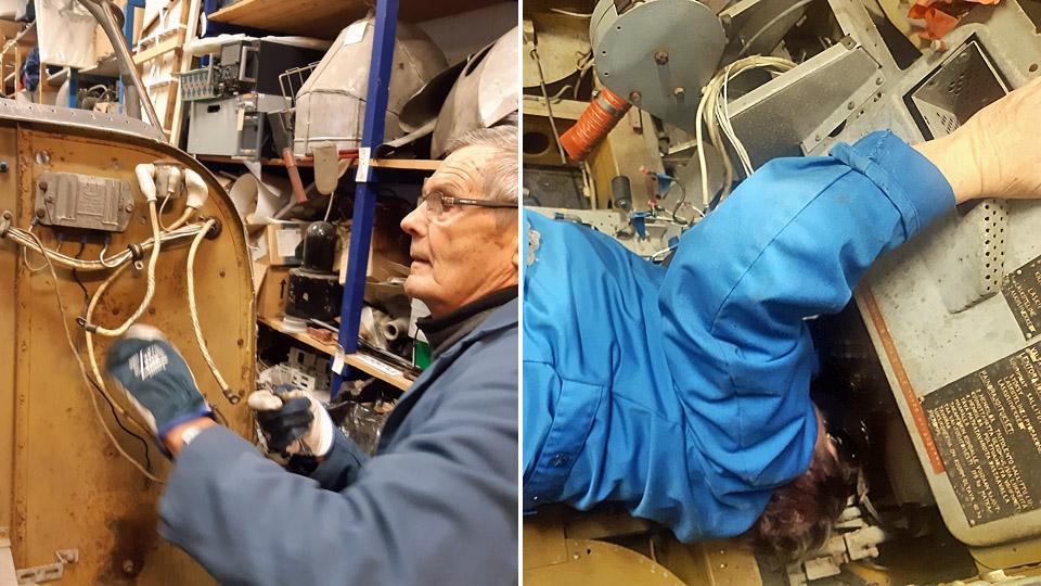
As the wires and gadgets were dismantled, they were marked and put into bags or boxes. The parts were also photographed before unfastening to facilitate their refitting. Part of the gadgets in the firewall were fastened with bolts through the firewall. These bolts, too, and with them the gadgets could be unfastened, when one of the club members crawled into the cockpit under the instrument panel, and reached and held the nut in place, when the bolt was wrenched open from the other side. Thus all the parts fastened to the firewall could finally be detached. The exhaust tubes going below the fuselage were unfastened from the engine bay bottom.
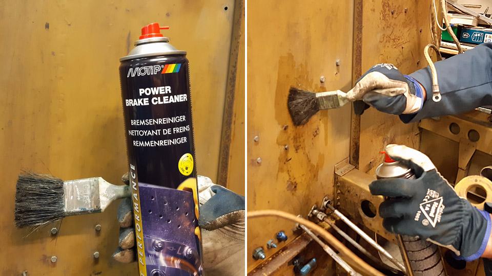
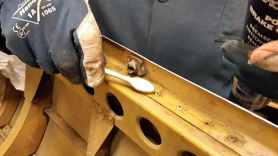
The engine bay surfaces were now ready for cleaning. First we vacuum-cleaned the surfaces from dust and dirt. After that the surfaces were cleaned with Motip Brake Cleaner. Now the cleaning liquid was acquired in spray form. The cleaning of the surfaces was advanced by small steps. First the cleaning agent was sprayed onto the surface. Then the dirt was taken off with a paintbrush or a small brush and finally swept clean with a piece of cloth.
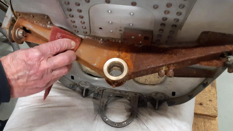
The Tuuli fuselage is without the tailplane. At the end of the cut off fuselage, there is a bulky metal support for the rudder axle. It’s covered with thick rust. The initial thought was to unfasten it for cleaning. Because the metal support is fastened to the end of the fuselage with rivets, we gave up the idea.
The surfaces of the metal support, and other rusty parts had their surfaces ground with a scouring pad, when most of the rust came off. Then the parts were dealt with an anti- grease substance and painted with aluminium-coloured rust-protecting Isotrol-paint. You can also apply Isotrol on a rusty surface because it penetrates the rust to the surface of the metal, preventing the corrosion from continuing. Photos by Lassi Karivalo. Translation by Matti Liuskallio. |
|
Avainsanat: aviation history, restoration, Tuesday Club, Valmet Tuuli III, OH-XTL, TL-1 |
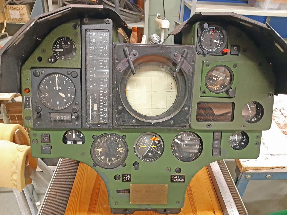
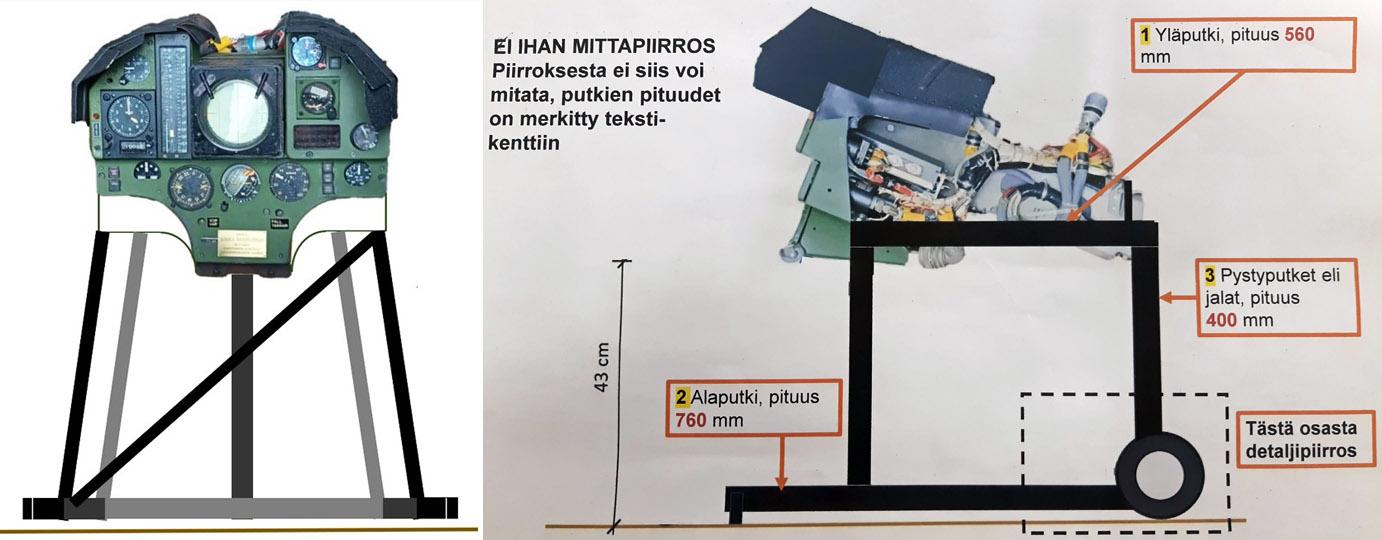
The Draken instrument panel into display artefactSunnuntai 21.1.2024 - Tuesday Club member Aviation Museum Society Finland received as a donation, a Saab J 35 Draken instrument panel entity, which was fastened to a sturdy wood panel. The society decided to make it into a showpiece that could be presented at Aviation Museum Society’s stands at fairs or airshows. Other times the instrument panel would be on display beside the Draken in no 1 Hall of the Finnish Aviation Museum. So far it’s not known to which sub-type of the Saab J 35 Draken the instrument panel belongs to.
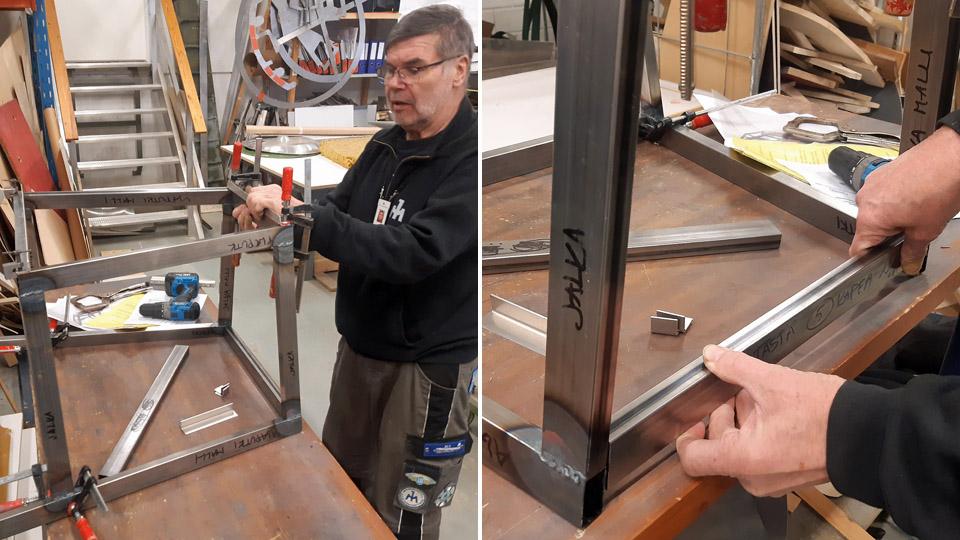
Making a display artefact requires that a safe rack must be built for the very heavy instrument panel entity. The rack will be built of metal and into such a form, that when sitting in front of the instrument panel with feet under it, the visitor can look at it just like the Draken-pilot would do in his cockpit.
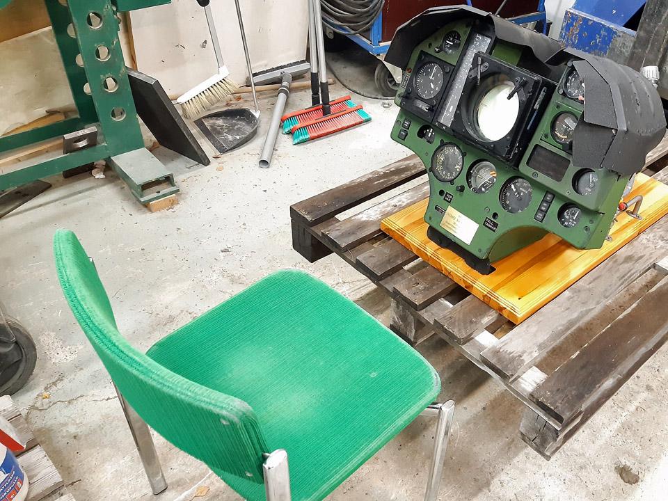
So it had to be defined, at which elevation the instrument panel has to be, for the before mentioned conditions to be fulfilled. We lifted the heavy instrument panel onto a transfer platform on the forks of a forklift. After that we put a chair in front of the forklift and adjusted the elevation of the platform so that the instrument panel is in the visitor’s field of vision. It was noted that 40 cm from the floor level to the lower edge of the instrument panel will be suitable.
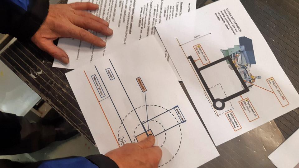
Drawings by Juha Veijalainen.
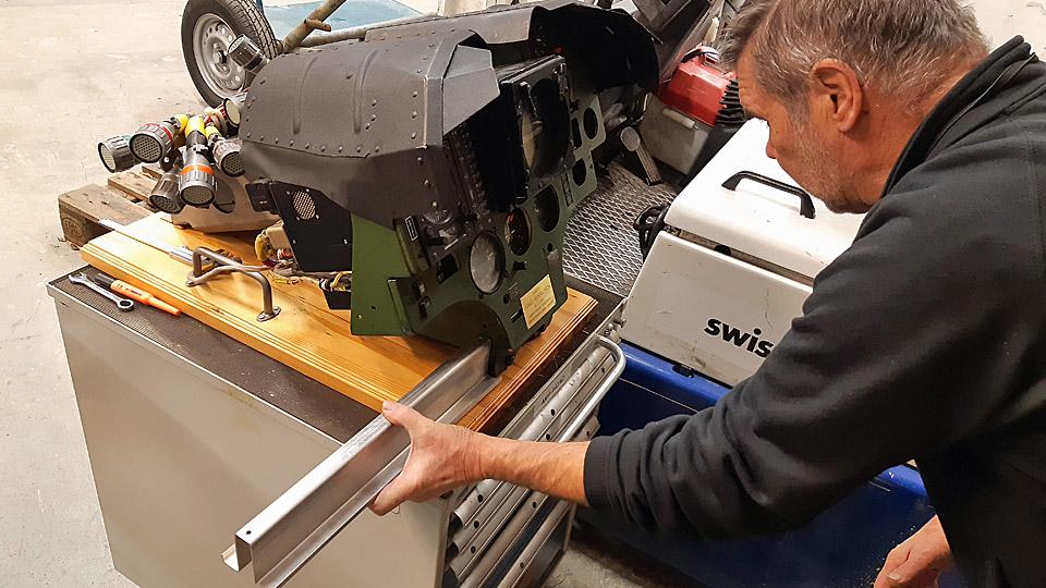
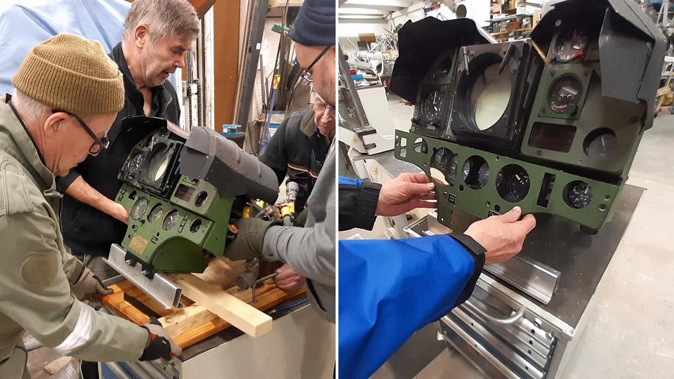
Now structural drawings and visualization images of the instrument panel rack could be made to build the rack. A solid and safe rack will be made of 20 mm x 40 mm steel tube. To make way for the rack, a lacquered wooden platform had to be unfastened from the instrument panel. Before unfastening the platform, a metal support was fastened to the lower edge of the instrument panel. The instrument panel was lowered on this support after unfastening the wooden platform.
We also detached a plaque fastened on the Draken instrument panel, saying that the instrument panel was a retirement present. To unfasten the plaque, we had to detach the front panel of the instrument panel. In place of the detached plaque we fastened a plaque, which said the instrument panel to be “that of the Saab J35 Draken-fighters, used by the Finnish Air Force”.
To build the rack for the instrument panel we bought a couple of bars of 20x40 mm metal tube. Pieces were sawn off the tube according to the drawings. The sawn pieces of tube were welded to one another. First the lower, upper and vertical tubes of both sides of the rack were welded together. After this, the rack was tentatively put together by fastening between both sides the cross bars of the lower and upper parts of the rack with clamps. It was noted that the rack will be just as we planned it. The next phase is to weld the cross bars to the sides of the rack, after which the instrument panel rack will be structurally ready.
Photo by Juha Veijalainen.
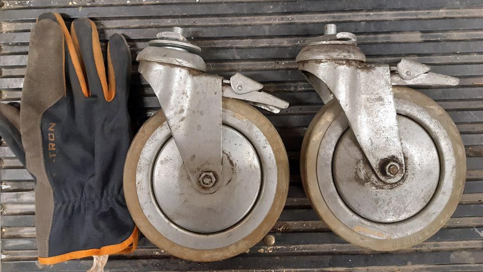
The Draken instrument panel with its rack is heavy, so moving it about is challenging. To facilitate the moving, the rear ends of the lower bars of the rack will be equipped with wheels. On top of that, sliding shafts will be built to the front end of the upper tubes. The shafts will slide inside the tubes, so the instrument panel will be movable like a wheelbarrow. We found a suitable set of trolley wheels of 150 mm in diameter at the storage of the Finnish Aviation Museum.
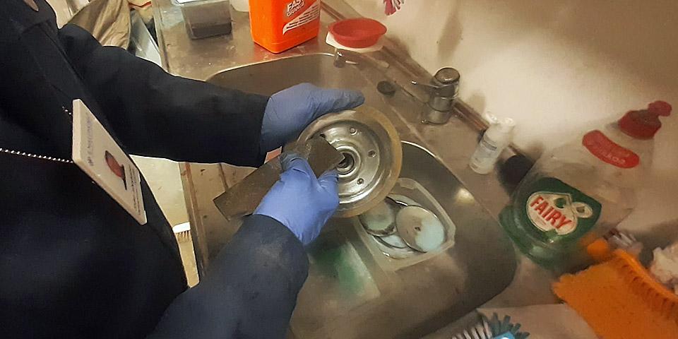
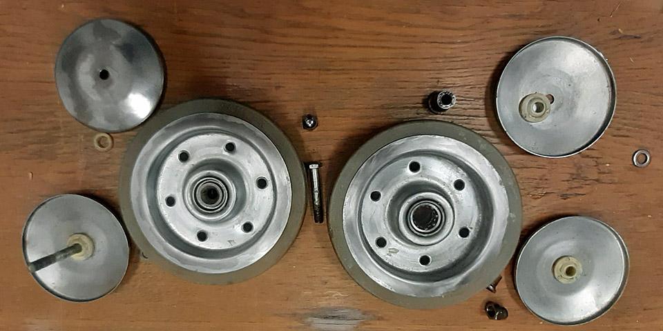
The 360 degrees revolving stem of the wheel was detached from them, because on the instrument panel rack the wheels will be fixed. Both wheels were taken apart and their bearings were serviced to operating standard.
Next the rack will be welded together to form an entity, after which the instrument panel can be fastened to the rack. After the lower bars have received their wheels and the shafts have been made, the rack will be painted. After that the donation to Aviation Museum Society Finland will be ready to be moved beside the Draken in the Finnish Aviation Museum. Photos by Lassi Karivalo except if otherwise mentioned. Translation by Matti Liuskallio. |
|
Avainsanat: aviation history, restoration, Tuesday Club;Saab J35 Draken |
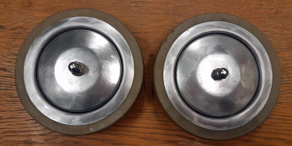
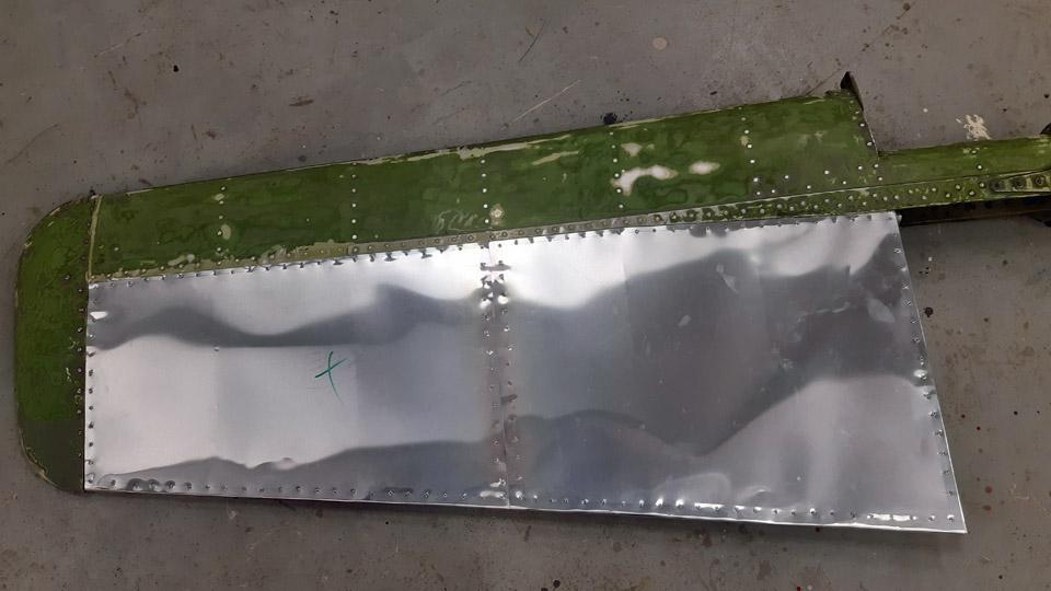
Painting of the Mi-8 helicopter tail boom stabilizersTiistai 16.1.2024 - Tuesday Club member The restoration of the Karalian Aviation Museum situated Mil Mi-8T (HS-4) tail boom stabilizers has been concluded. It started at the Tuesday Club in the autumn season 2023. The decayed covering fabrics of the stabilizers of aluminium structure were removed and the stabilizers were covered with weatherproof thin aluminium sheets instead of fabric. Because it was decided to paint the stabilizers all round, the worn paint surfaces were ground ready for painting. The priming of the stabilizers has been described in an earlier blog.
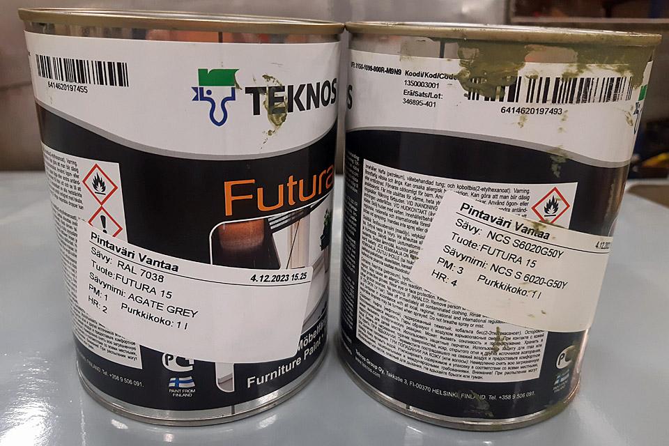
The stabilizers of the tail boom will be painted according to the paint scheme used in Mi-8 helicopters in the Defence Forces. The upper surfaces will get a camouflage colour AN 22 green (Light bronze green), which compares to the NCS-shade map NCS S6020-G50Y. The under surface will be light grey (Light aircraft gray), which corresponds to the RAL shade map RAL 7038. As the surface paint the Teknos Futura 15 outside furniture paint was chosen. Corresponding to the aforementioned shades, the grey and green paints were bought at the Pintaväri Vantaa branch.
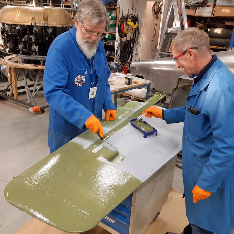
The painting was started from the upper surfaces with the green Futura. The smooth surfaces were painted with a narrow mohair roller. Uneven surfaces like the rivet studs, the stabilizer stem and the strut were painted with a brush. The first time over gave a fairly good coverage, but to achieve a good surface the stabilizers have to be painted twice over.
After the green paint had dried, the under surfaces were painted once over with the light grey Futura. This paint, too, gave laudable coverage with the first painting. However, the under surfaces were painted a second time over after the paint had dried, to achieve an even and well protecting surface.
We still had to paint the stabilizers’ upper surface for a second time. The painting of the upper surface for the second time was left last, because at the seam of the upper and under surfaces of the stabilizer, the green paint gives a good coverage over the light grey paint. In this context the green and grey border surface of the stabilizer was taped over with painter’s tape. Another option would have been to paint the border area with a roller without masking. However, we ended up with masking, because it produces a neat and tidy straight border between the grey and green paint.
When masking is used in painting, it’s important to take off the masking tapes immediately, before the paint dries. If you leave the tape in place till the paint is dry, when taking the tape off it easily tears dried paint along, and the neat border that was meant to be achieved by masking, will be lost.
The Mil Mi-8T helicopter of the Karelian Aviation Museum has now had its tail boom stabilizers restored and they are ready to be delivered to Lappeenranta. Photos by Lassi Karivalo. Translation by Matti Liuskallio. |
|
Avainsanat: aviation history, restoration, Mil Mi-8, HS-4, Tuesday Club |
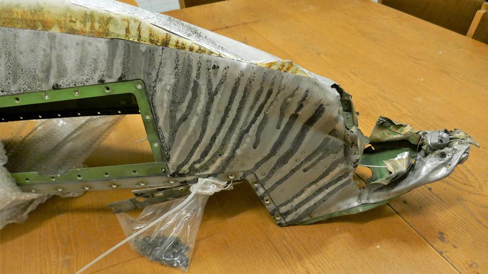
Repairing the Caravelle right-hand wingtipSunnuntai 14.1.2024 - Tuesday Club member Acquired from Sweden by Aviation Museum Society Finland, the Caravelle (OH-LEA) restored at Turku airport as Finnair’s “Bluebird” had had its right-hand wingtip leading edge badly damaged during its stay in Sweden. It was damaged for a distance of ca. 40 cm, and at the process the wingtip navigation light was also destroyed. Luckily the left-hand wingtip is intact, so that it can be used as a model when rebuilding the right-hand smashed wingtip. So the destroyed wingtip must be remade.
The remaking the right-hand wingtip was started by dismantling the damaged area. The rivets on the crumpled aluminium sheets were drilled away, so that the wingtip covering could be bent open, and the covering sheets detached from the wingtip support frame. We tried to straighten the detached aluminium sheets to their original shape, but they turned out to be so brittle, that they broke when straightened to their shape. So we concluded that the right-hand wingtip leading edge had to be covered with new sheets of aluminium.
We dismantled the detachable support frames of the damaged area. Part of the structure didn’t need to be detached, so it could be used as such in reconstructing the wingtip leading edge. The detached and usable frames were straightened to their original shape. They were fastened with pop rivets to their places, utilizing the intact left-hand wingtip when positioning the support frames.
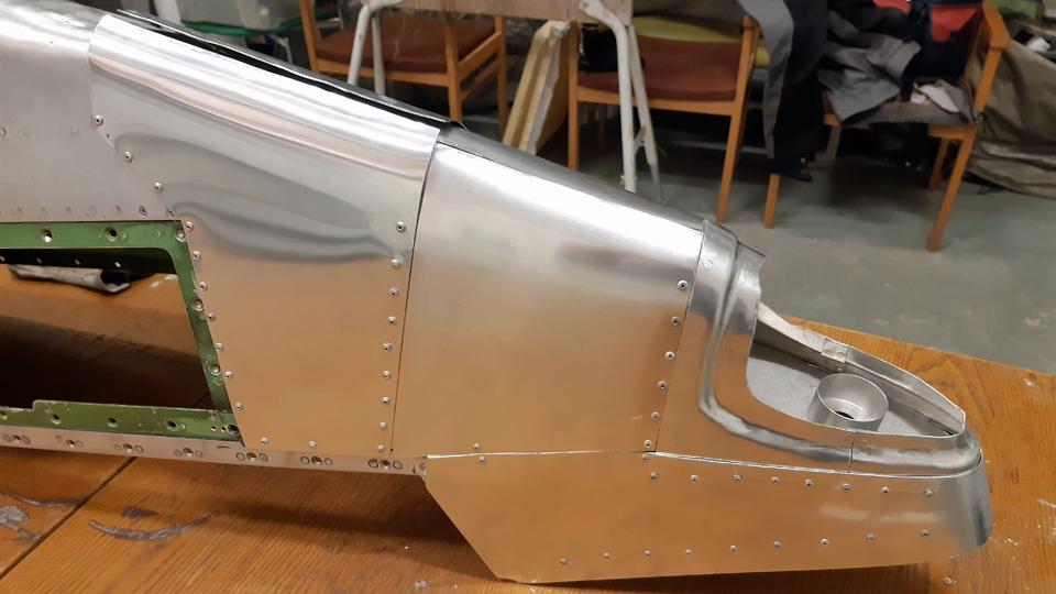
After this the back wall and bottom plate of the right-hand wing navigation light bay was constructed with the left-hand wing navigation light bay as a model. The back wall and bottom plate were cut off from 1 mm thick aluminium plate. When the navigation light bay back wall and bottom plate were tentatively in place, the wingtip leading edge was nearing its original shape.
An opening was made in the bottom plate of the navigation light for the wiring of the navigation light. Also a cup-like socket was lathed for the later fixing of the light in mind. After that the whole navigation light bay was locked from its edges to the remaining original frames of the wingtip with strips cut from 1 mm thick aluminium plate. The fastening was done with pop rivets.
The next phase was to make a support frame between the edge of the intact area in the wingtip and the back wall of the navigation light, where the original frame had been destroyed. The edge of the intact area is formed by the wingtip’s original curve. However, the curve is somewhat damaged in its upper edge, but repairable and will be hidden by the wingtip new covering.
The support frame was made of 2 cm wide strips cut off from 1mm thick aluminium plate. To be able to rivet the ends of the support frame strips to the edge of the curve, the original damaged aluminium covering which had been on the frame, was cut off with a Dremel blade. Five strips were fastened between the edge of the curve and the back wall of the navigation light. The fastening was made with pop rivets. To make the structure sturdy enough to bend and fasten the aluminium cover sheets on the frame, two additional crosswise support strips were riveted to the structure. Now we’ll be ready to start covering the right-hand wingtip leading edge with 1 mm thick aluminium sheets. Photos by Lassi Karivalo. Translation by Matti Liuskallio. |
|
Avainsanat: aviation history, restoration, Caravelle, OH-LEA, Sinilintu, Bluebird, Tuesday Club |
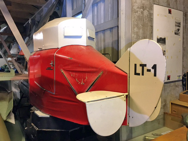
The wings of a Link Trainer to the Tuesday Club to be coveredSunnuntai 3.12.2023 - Tuesday Club member The collection of the Karelian Aviation Museum includes a Link Trainer (LT-1). This Link Trainer has last been in use at Immola. The retired link Trainer was collected in a trailer to the Karelian Aviation Museum to Lappeenranta on June 6th, 2004.
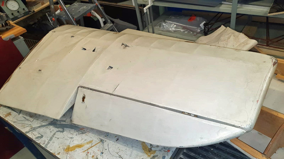
Photos by Kimmo Marttinen. This Link Trainer has wooden wings with ailerons. The fabric covering of the wings is badly torn. On top of that the left aileron is missing. The wings are structurally more or less intact, so for that part there isn’t much to repair.
Photos by Ari Aho. The chairman of the Karelian Aviation Museum, Mr Kimmo Marttinen, turned to the Tuesday Club, whether the Tuesday Club could cover anew the LT-1 wings. The Club has several restoration projects active, but we answered in the affirmative because the wings are tiny, and their covering anew won’t take much room. The LT-1 wings were brought from Lappeenranta to the Finnish Aviation Museum at the beginning of November.
Photo by Ari Aho.
Photo by Kimmo Marttinen. At the Aviation Museum we examined more closely the Link Trainer’s fabric covered wings. There were damages on the covering of the upper surface of both the wings, but they could be patched. The covering of the underside of both the wings, instead, was badly damaged. However, we decided to cover both wings anew, because the end result wouldn’t be tidy, if it consisted of both old patched and new fabric covered surfaces.
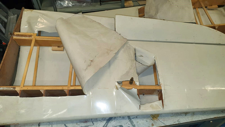
Before we started to dismantle the covering, the right-hand wing’s aileron was taken off. Even though the covering was intact, it was dismantled. The reason for this being that we’ll have to build the lacking aileron for the left-hand wing, and for that we needed the structure of the right-hand aileron as a model. The structure of the aileron for building the lacking one can’t be seen without taking off the covering from the aileron.
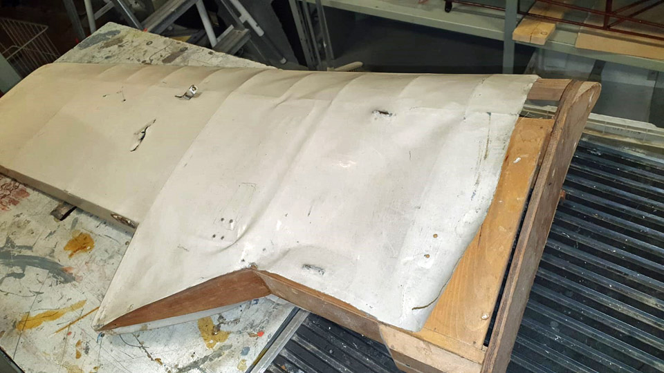
When dismantling the covering fabric from Link Trainer’s wings, our attention was drawn to the thickness of the covering fabric. At the same time it was noticed that where there was damage in the fabric, silver and dark blue paint appeared from under the beige paint. The Link Trainer’s wings have originally, or before the last coat of paint, been blue on the upper surfaces and silver on the undersurfaces.
The covering fabric also told us that the wing had been covered with fabric consisting of several pieces sewn to each other. While covering the wing the stitches have been hidden with strips of fabric with zig-zag edges put into place with tightening lacquer to protect the seams.
When scrutinizing the wings stripped of the fabric, we noticed that the stem of the left-hand wing differed in form from that of the right- hand wing. Could it be that the entrance to the Link Trainer is on the left-hand side, therefore “a sidestep” has been made to the wing stem to facilitate entering the Trainer cockpit. We also noticed that the gluing seam in the wing structure had opened in places. These seams must be glued before commencing the covering. The airframe of the wing and aileron are very well and meticulously done, and also very typical wing structure with spars and ribs. Actually one wonders why the wing has been made so complete, because the Link Trainer’s wings weren’t meant to be airworthy. It would have been easier to construct the wings, if the wing had been made of plate, cut into wing form, as is the case in some Link Trainers. Before we get to covering the Link Trainer’s wings, we must find a suitable fabric. In this case an ordinary white cotton fabric will do, as long as it has good tightening qualities. So we bought two different kinds of cotton fabric from Eurokangas for testing the tightening qualities (Bed sheet fabric 150 and Satin), whose tightening qualities we now will test with nitro cellulose lacquer. Hopefully one of them will meet our requirements in covering the Link Trainer’s wings. Photos by Lassi Karivalo except if otherwise mentioned. Translation by Matti Liuskallio. |
|
Avainsanat: aviation history, restoration, Tuesday Club, Link Trainer |
The plywood covering of OH-XEA Ressu is under repairPerjantai 1.12.2023 - Tuesday Club member Ressu’s restoration has progressed well in the Finnish Aviation Museum’s restoration workshop. The left wing, ailerons, vertical stabilizer, rudder, horizontal stabilizer, wing struts and tail wheel assembly are all now under work. Maybe we should actually be talking about repairs, because Ressu is mainly in good condition – except the fuselage and vertical stabilizer. Therefore we mainly concentrate on repairing the damages in the plywood covering.
The aim in repairing the damages in Ressu’s plywood covering is to save as much of the original plywood as possible. Where a blow has damaged the covering and the plywood is still a strip which is in one piece, we aim to repair the damage by gluing the strip back into place, using a supporting piece of new plywood. However, if the damage is an open hole, the plywood is shattered, or there is a piece of plywood missing, we will patch the damaged area with new plywood. The latter repairing method is introduced in this blog, using the repair of the damaged plywood covering on the elevator as an example. In all cases the glued seams of the patches are spackled and sanded, and the patched area is painted to the original hue of the painted surface so that the damaged area can hardly be noticed.
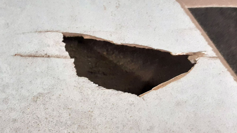
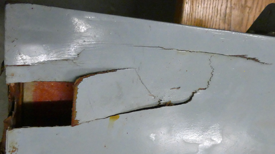
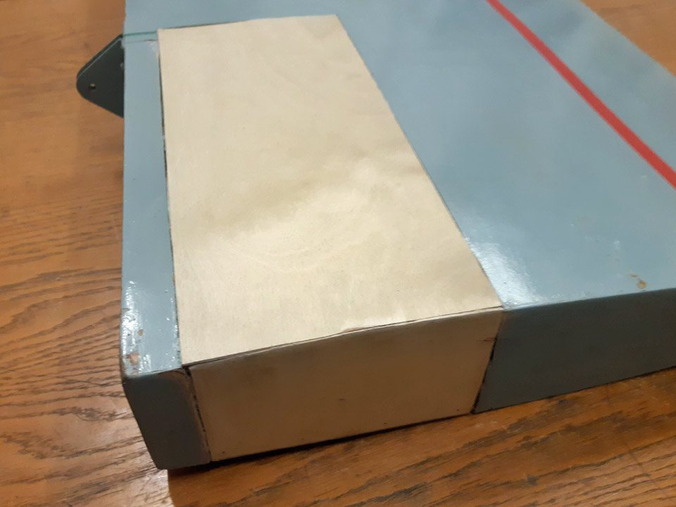
The plywood covering of Ressu’s elevator had one larger damaged area to be repaired. The damaged area is located on the elevator’s left-hand end, in the trailing edge side corner. Here the plywood covering has been broken on the elevator’s upper side and on its end. The plywood has broken in several places and parts of the covering are missing. We decided to patch the whole damaged area with new plywood.
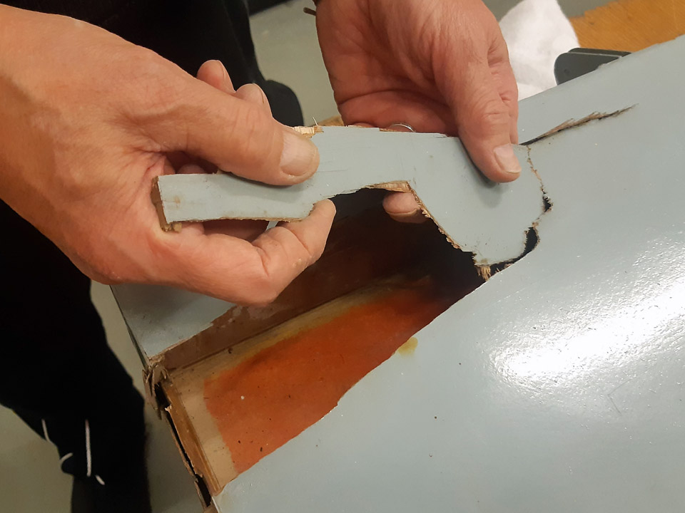
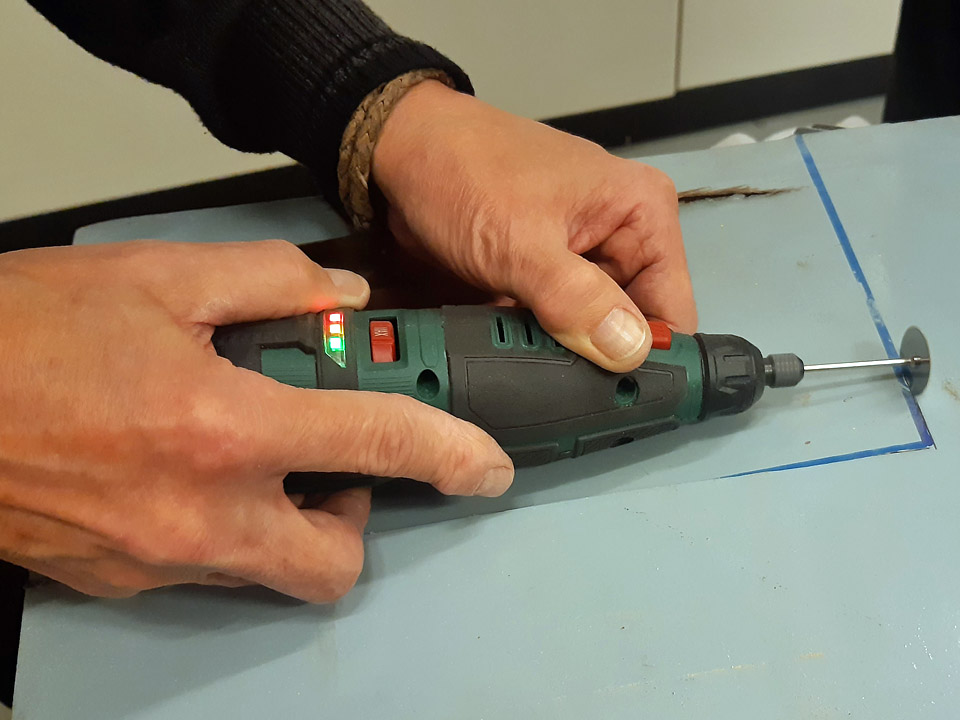
First we removed the broken pieces of the covering plywood at the damaged point on the upper surface. Then we drew a rectangle around the damaged area and cut the plywood off along its edges, using a Dremel circular saw blade. This is how we created an opening for the patch on the upper surface. In a similar manner we cut a rectangular opening around the damaged area on the elevator’s end. Now the whole damaged area had been opened for patching.
The next step was to fasten supporting strips on the edges of the opening. The plywood patch will be supported by these strips when it is glued to cover the opening. Some of the supporting strips were glued with strengthening nails to the structure of the elevator. A strip was fastened also on the area where the patches on the elevators upper surface and on its end meet, i.e. at the upper edge of the elevator’s end.
Photo by Antti Hietala. One of the supporting strips was glued on the underside of the plywood edge so that a little less than one centimetre of the strip was left outside the plywood covering’s edge. Before gluing, the old varnish was sanded away from the underside area of the plywood covering which was to be glued. The supporting strip was glued on the edge of the plywood covering and pressed tight on the plywood with small plastic clamps. The glue we used was Casco Outdoor wood glue. Furthermore, a longitudinal supporting strip was fastened across the opening on the upper side. This strip is needed to support the plywood patch on the opening and make it slightly curved so that it follows the gently curving profile of the elevator’s upper surface.
When the supporting strips had been fastened, patch pieces of 1 mm aircraft plywood were cut for the openings on the upper side and the elevator’s end. The patches were fitted into place, shaping their edges until the patch edges pressed tightly against the sides of the opening.
Photo by Matti Kainulainen. First the plywood patch was glued into place on the elevator’s end. The upper edge of the patch was pressed against the supporting strip with small clamps and the glued seam on the lower edge was secured with some small nails.
Photo by Matti Kainulainen. Then the larger patch on the upper surface was glued into place. On the elevator’s leading edge side, the glue seam of the plywood patch could be pressed tight with ordinary clamps. A piece of plywood was placed between the clamps and the glue seam to distribute the pressure evenly on the seam. On the other side of the opening a metal weight was placed on the glued seam to press the plywood patch against the supporting strip.
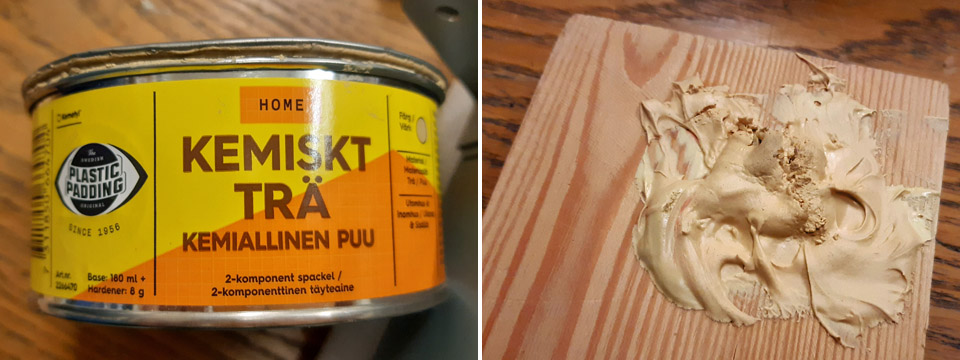
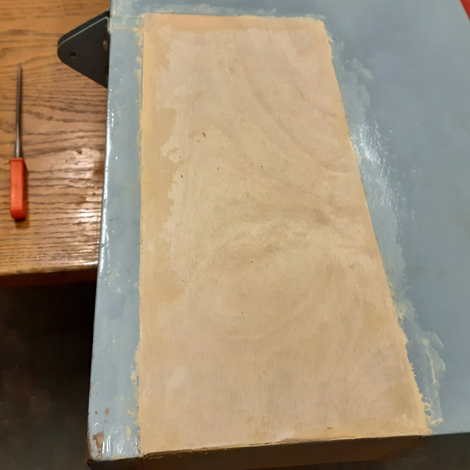
The gluing of both plywood patches went well. The patch seams were spackled using Plastic Padding’s two-component Chemical Wood. The spackled seams and the whole newly patched area will be sanded before painting. The plywood patches will be painted later, together with several other plywood patches on Ressu’s surfaces. Photos by Lassi Karivalo except if otherwise separately mentioned. Translation by Erja Reinikainen. |
|
Avainsanat: aviation history, restoration, Tuesday Club, Hietanen HEA-23b, OH-XEA, "Ressu" |
Priming the HS-4 tail boom stabilizersTorstai 30.11.2023 - Tuesday Club member When both the fabric covered areas of the Mil Mi-8T (HS-4) helicopter tail boom stabilizers had been covered with thin 0,3 mm aluminium offset printing sheet, we could move on to priming these new aluminium surfaces. Obviously, the decayed fabric coverings were renewed with aluminium sheets instead of fabric.
Right hand side photo by Mårten Juslin. The first phase in priming is to remove grease and dirt from the surface to be painted. KUSTOM-anti grease agent was used to remove the grease. The agent was applied to clean cloth and both stabilizers’ new aluminium surfaces were meticulously wiped with it. The anti-grease operation for other surfaces of the stabilizers will be done in conjunction with the paintwork because their surfaces are already set up for the paintwork.
Photo by Mårten Juslin. The next step is the graining of the new aluminium surfaces to be adhesion-primed, especially as the HS-4 tail boom stabilizers’ new surfaces are smooth like a mirror.
Photo by Mårten Juslin. The graining of the new aluminium surfaces was done with a traditional scouring pad. After graining, the graining dust was wiped off the surfaces with a clean cloth. It was noticed that more dirt had accumulated to the cloth used for wiping off the grease and dirt than to the cloth used for wiping off the graining dust. This goes to show, how important part of the priming, the removal of grease and dirt is.
Right hand side photo by Ari Aho. As a primer or adhesive primer we chose the handy spray paint (Car System Prefill Spray Miranol) and its tone (RAL 7005). Light grey is in this case a good tone for the adhesive primer, because the stabilizers’ undersurfaces will be painted light grey (Light aircraft grey).
Photo by Mårten Juslin.
The stabilizers that were ready for priming, were taken to the painting tent at the yard of the Finnish Aviation Museum. There the primer was misted on the stabilizers’ surfaces as a thin, but engulfing veil. The stabilizers are now ready for the paintwork. Photos by Lassi Karivalo except if otherwise separately mentioned. Translation by Matti Liuskallio. |
|
Avainsanat: aviation history, restoration, Mil Mi-8, HS-4, Tuesday Club |
Ilmailumuseot.fi - Aviationmuseums.fi