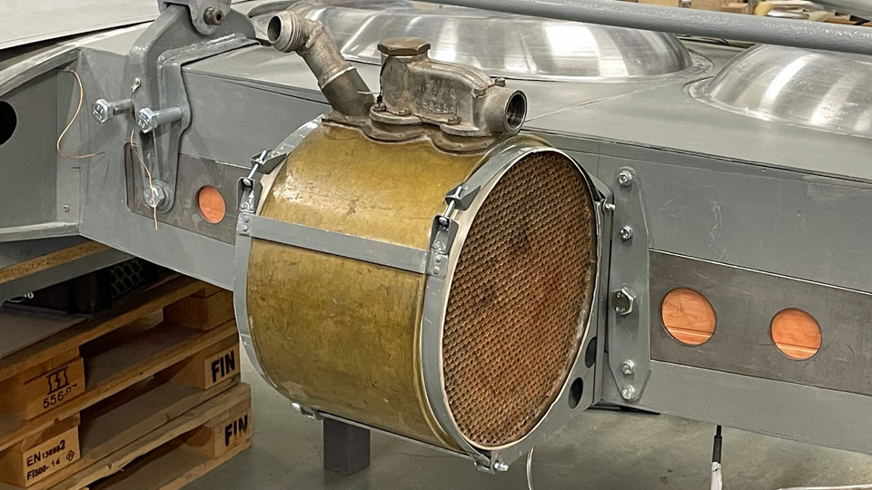
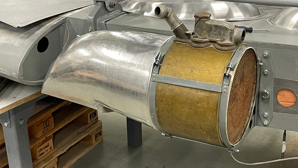
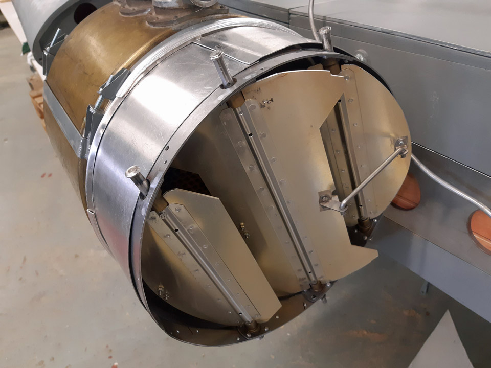
Time to test-fit the Myrsky oil coolerLauantai 19.8.2023 - Tuesday Club member Parallel with the fitting of the wing root fairings, the test-fitting of the barrel-shaped oil cooler was commenced. The Myrsky oil cooler is situated in the fuselage centre line, attached to the main spar “forehead”. Air comes to the oil cooler through an air duct from the left-hand wing’s leading edge. Respectively, after going through the oil cooler the air exits from the underside of the right-hand wing. For the MY-14 fighter restoration we have at our disposal an original Pratt & Whitney R-1830 Twin Wasp engine’s oil cooler, the very engine that powered the Myrsky. We received it from Airveteran Oy. Instead we have had to manufacture all the accessories for the oil cooler, including the ducts for the supply and exhaust air and the dampers adjusting airflow. The air ducts were made of 1mm thick, easily workable aluminium sheet. The pieces cut off the sheet were shaped in wooden shaping lasts, after which the seams were welded. We also made the dampers or gills that adjust the amount of air going through the oil cooler. The dampers adjusting the amount of supply air are controlled mechanically from the cockpit.
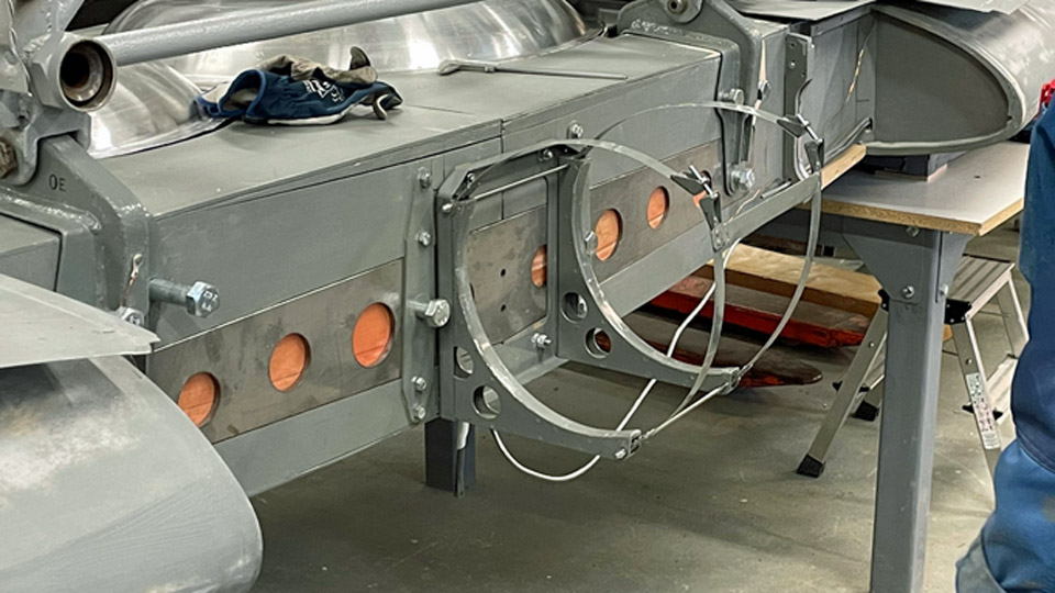
Photos by Heikki Kaakinen. Normally the oil cooler is permanently attached to the main spar. Because the MY-14 wing is made of two halves and the oil cooler is situated at the junction, the oil cooler must always come off, when and if the Myrsky will be dismantled for transportation to another museum or some other place to be placed on display. That’s why a handy rack with attachment straps was constructed. The oil cooler will be strapped on it and the rack is easily detachable from the wing spar and can also easily be reattached.
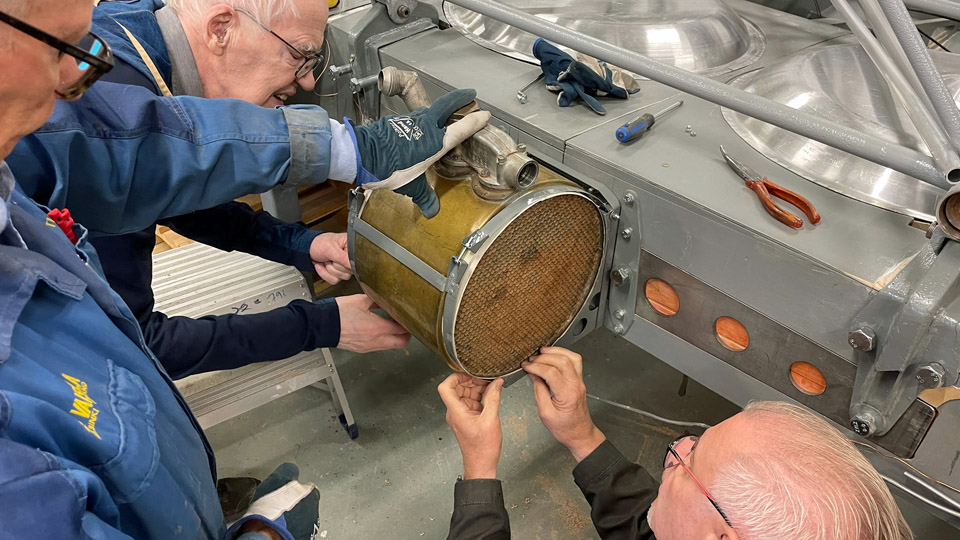
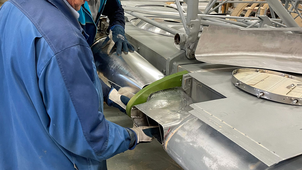
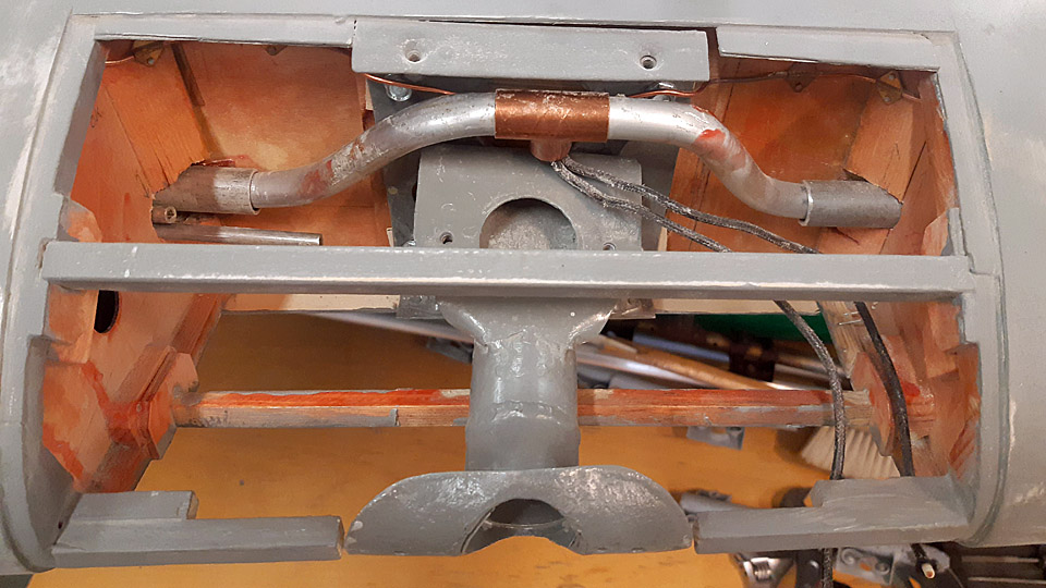
Photos by Heikki Kaakinen The test-fitting of the oil cooler was started by attaching the oil cooler attachment rack on the junction of the wing halves. The oil cooler was tightened to the straps. After that the cooler’s right-hand cooling air exhaust duct was fitted into place. The duct opens to the underside of the right-hand wing’s leading edge.
Photo by Heikki Kaakinen
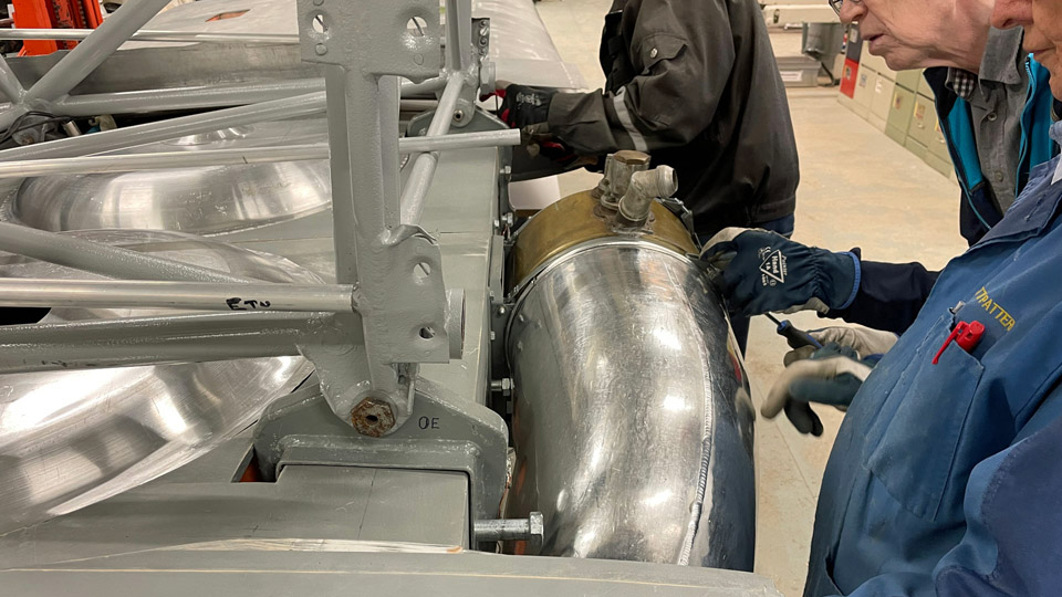
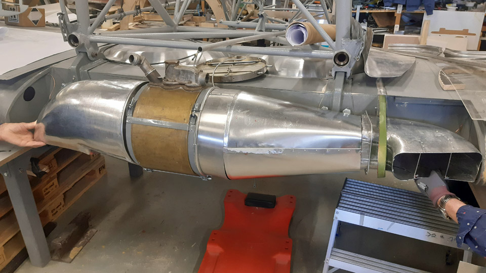
The gills adjusting the incoming airflow were attached to the other end of the oil cooler. The gills are situated between the oil cooler and the supply air duct. The duct for incoming air is twofold. One end of the duct’s straight part is attached to the supply air damper and the other end to the front end of the L-shaped supply air duct. The opening of the incoming air duct is situated in the right-hand wing’s leading edge. There’s still work to do in fitting the oil cooler parts before every part is settled in its place as planned. A veritable “collection of gadgets” this Myrsky oil cooler system has proved to be.
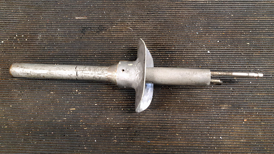
The pitot-tube, which measures the airspeed of the aircraft and is situated on the left-hand wing, was also test-fitted. The pitot-tube rack has been in place for long in the left-hand wing’s leading edge. We noticed, to our chagrin, that the 300 mm pitot-tube at our disposal was of a wrong length. It should be of the 500 mm long type. This can be seen in the Myrsky blueprints and photos taken of the Myrsky. Might there be a pitot-tube of the right length for us in the collections of the Finnish Air Force Museum?
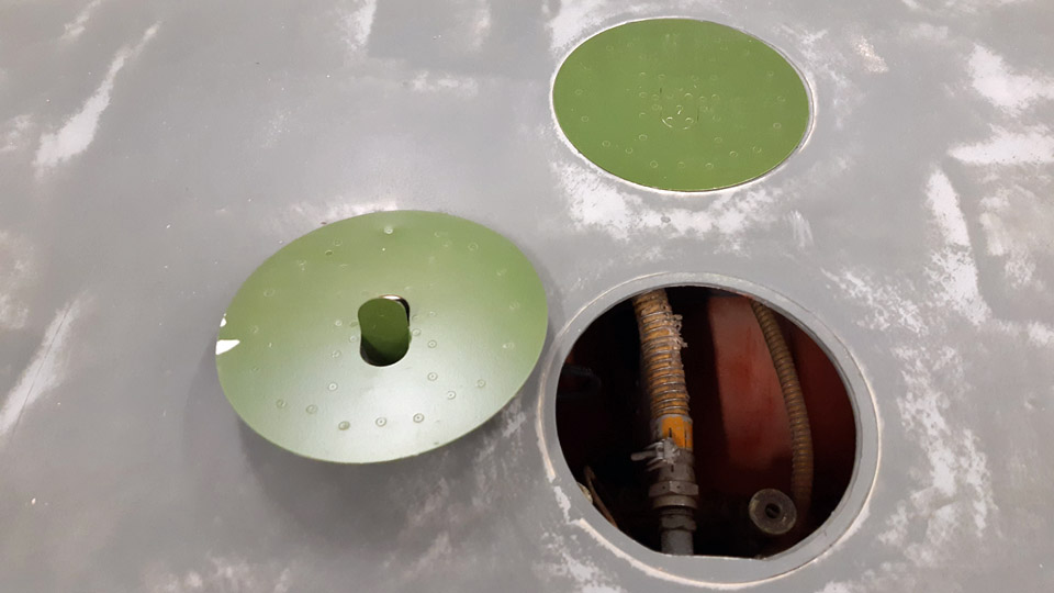
Along with all other tasks numerous inspection hatches on the wings are being fitted into place. We had to grind the collars of the hatches a bit deeper, so that the hatches would become flush with the wing surface. Photos by Lassi Karivalo except if otherwise mentioned. Translation by Matti Liuskallio. |
|
Avainsanat: aviation history, restoration, MY-14, VL Myrsky, Tuesday Club |
Ilmailumuseot.fi - Aviationmuseums.fi