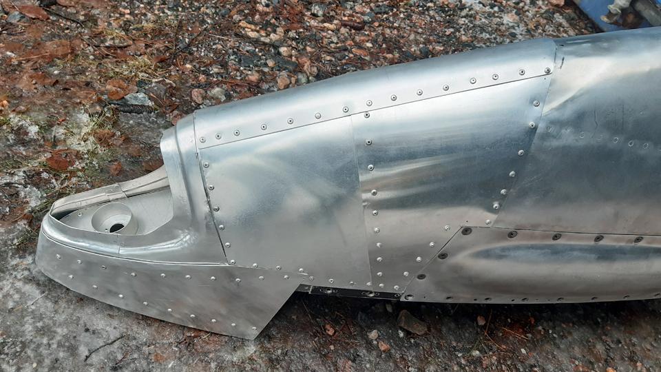
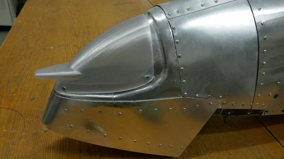
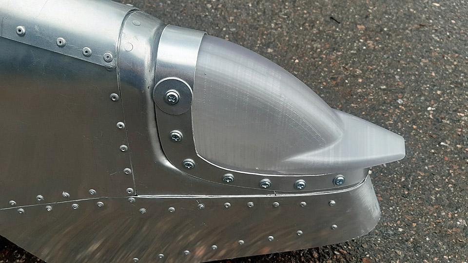
Caravelle right-hand wingtip is finalized with the navigation light globeLauantai 27.4.2024 - Tuesday Club member When the new leading edge had been built to replace the destroyed right-hand side wingtip leading edge on the Caravelle III (OH-LEA Bluebird), we could begin the installation of the navigation light globe into its place on the leading edge. We don’t have the original navigation light globe because it has been destroyed together with the wingtip. We could not find a globe as a spare part either, so we had to make one. We chose to do this by 3D-printing. We used the partly broken navigation light globe from the left wing as a model. A new globe was printed for the right wing and also for the left wing navigation light.
The new navigation light globe was installed on the OH-LEA Bluebird’s left-hand wing earlier in the summer of 2023. The right- hand wing, however, had to wait until March 2024 for its new globe to be put already in early into place after the new leading edge of the destroyed wingtip had been finished.
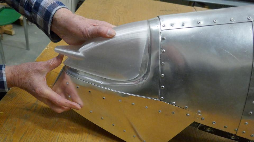
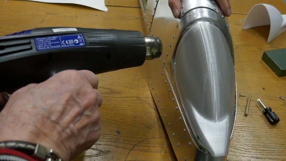
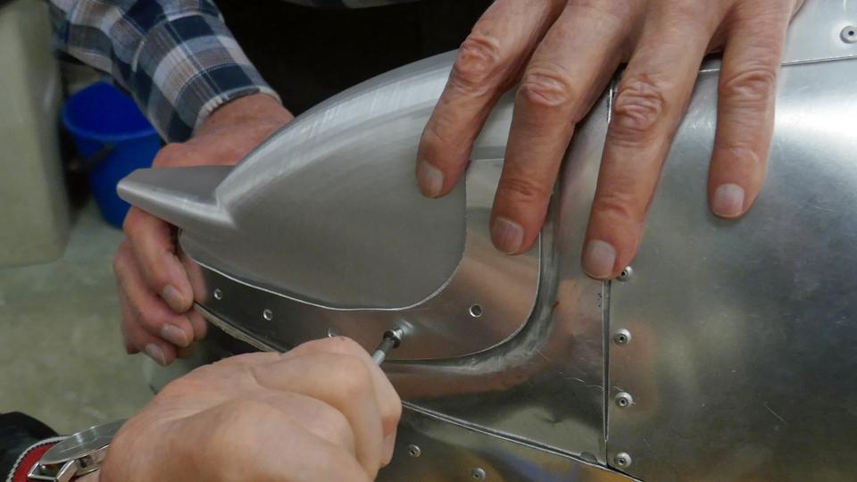
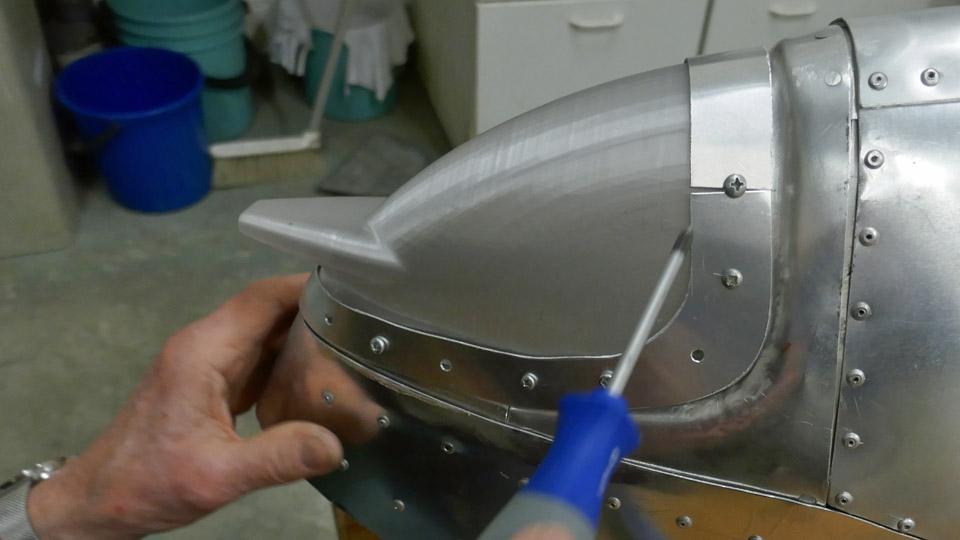
The 3D-printed navigation light globe is made of stiff plastic, and in the beginning it didn’t fit properly into place. We heated the globe with a hot air blower so that it could be moulded to fit into its mounting on the wingtip. The globe was fastened tentatively on the edges of the mounting with a couple of screws. This was necessary for holding the globe in place while making the fastening frame. The globe is fastened on the aluminium edge of its mounting with a frame. The frame has holes for screws, and it presses tightly against the sides of the globe, and the screws in the frame holes are tightened through the globe edge into the aluminium edge underneath.
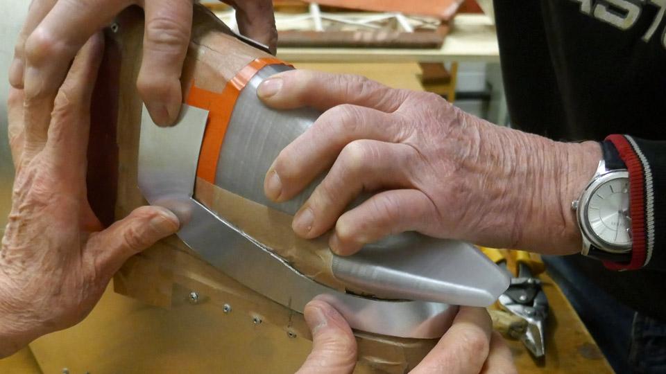
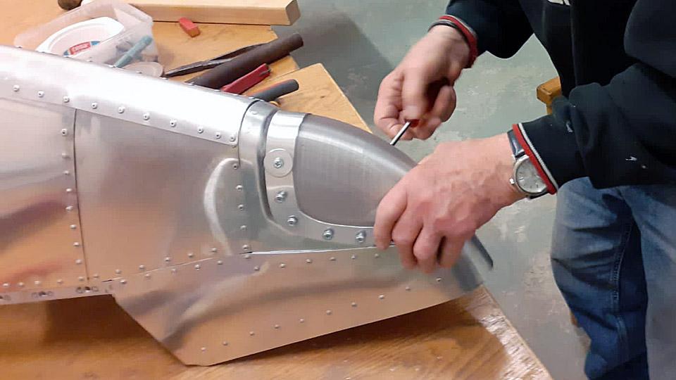
Diverging from the original solution, we decided to make the fastening frame for the globe from two parts. This made it easier to build the frame. Nevertheless, the frame we made will cover the most part of the navigation globe edge. A connecting piece will be needed on the top of the globe to connect the ends of the frame.
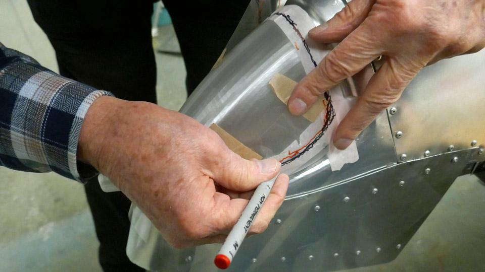
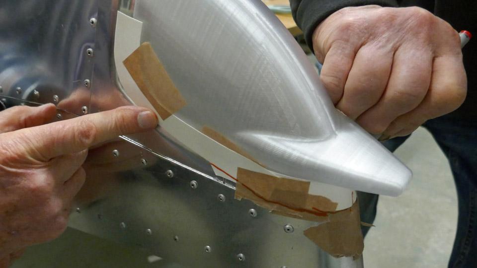
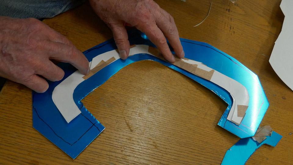
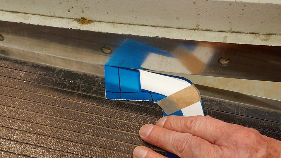
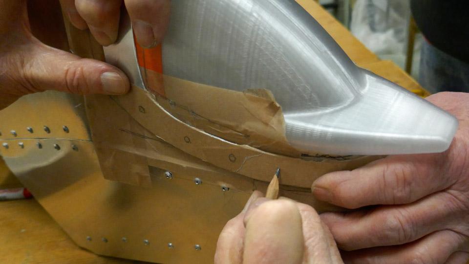
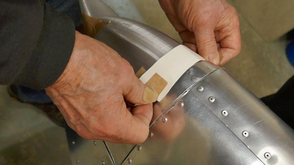
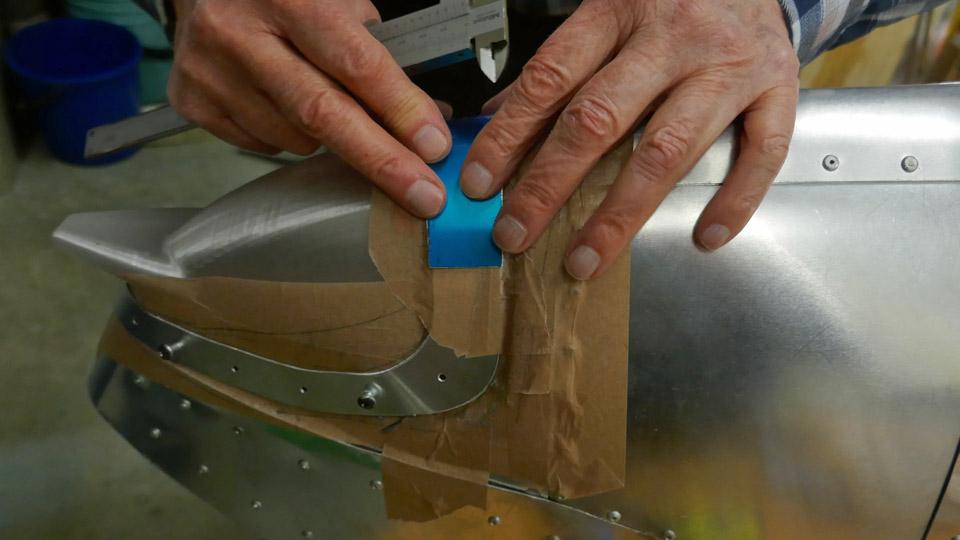
When the globe had been fastened with a couple of screws, broad paper tape was fastened on its edge. The shape of the globe frame was drawn on the tape. Based on the drawn line, a model for the frame was made of cardboard. The model was taped on a 1 mm thick aluminium sheet, which had already been pre-cut into the frame shape. After this we began to modify the sheet with a cutter to match the shape of the cardboard model.
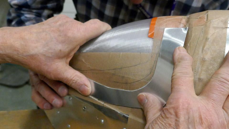
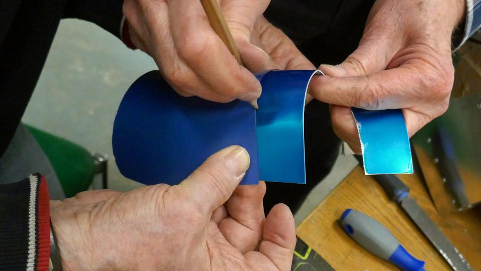
The aluminium frame was test-fitted into place and modified several times. Gradually the frame reached its final shape and it rested against the lower edge of the globe as §planned. When the desired shape had been reached, the blue plastic film which had protected the aluminium surface was removed from the frame.
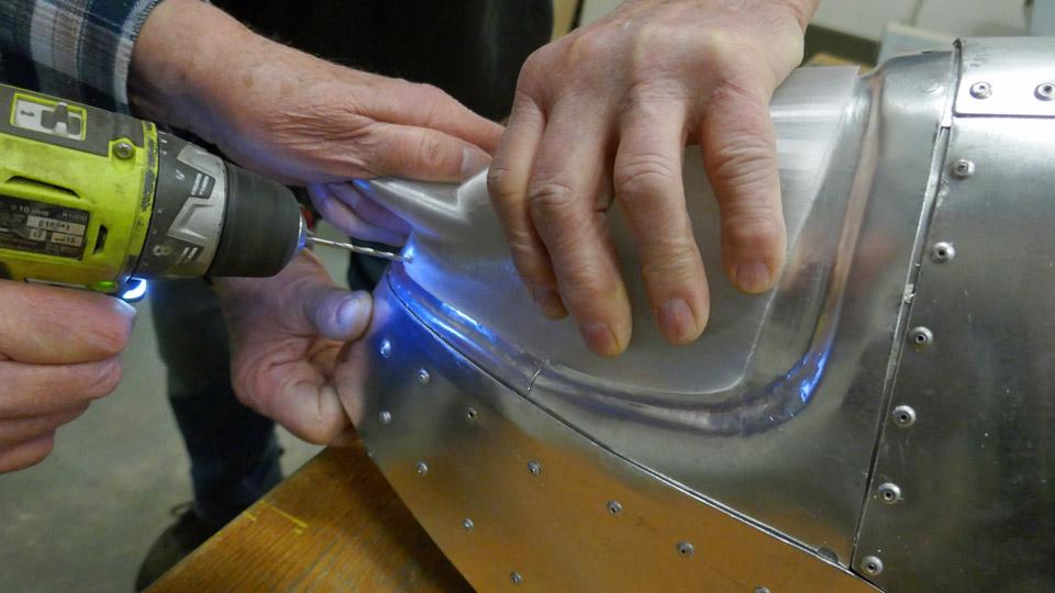
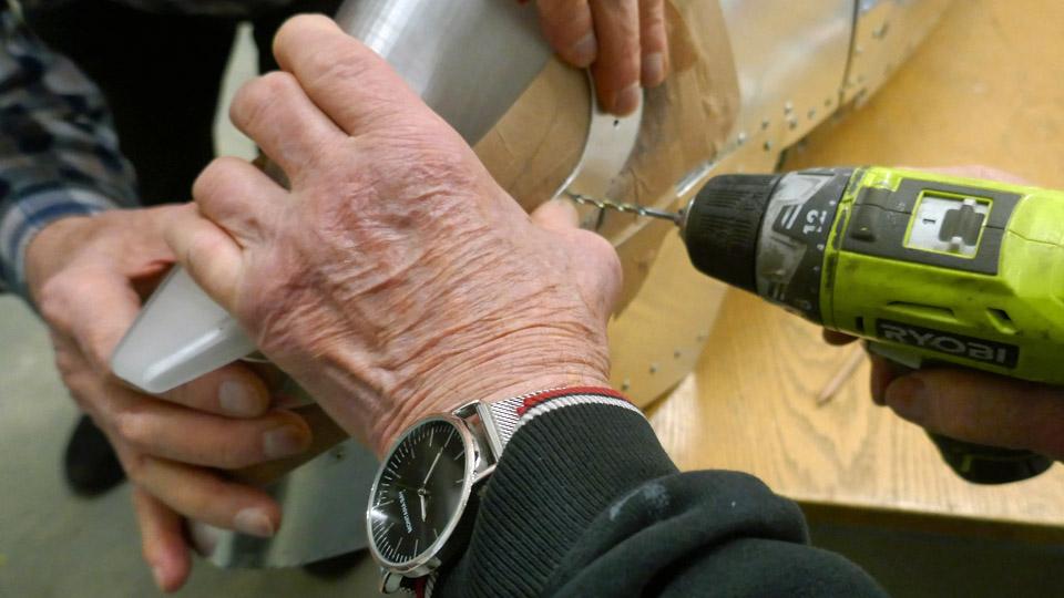
A strip of paper tape was fastened on the surface of the finalized fastening frame for marking the location of the fastening screws at regular intervals with a pencil. Holes for the fastening screws were drilled at the marked locations, then the screws were fastened one by one. This made the navigation light globe press into its place between the fastening frame and the edge of the globe mounting. Now the navigation light globe on the right-hand side wingtip was in place.
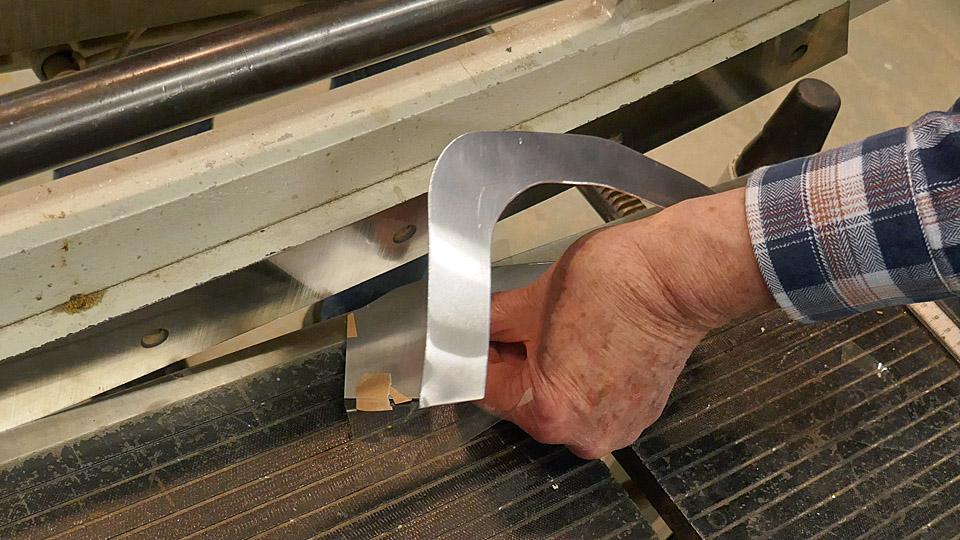
The last phase was to make the 5 cm connecting piece between the fastening frame ends on the top of the navigation light globe. First a cardboard model was made of the connecting piece. The connecting piece was cut and moulded from aluminium sheet, following the model. When the blue plastic covering had been removed from its surface, the connecting piece was fastened between the fastening frame ends, using two screws with washers. Finally the screws were tightened.
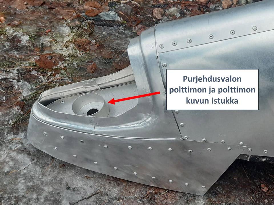
Under the globe, out of sight, is the socket for the navigation light bulb and its green glass globe. The socket was lathed from aluminium and installed into place at the Tuesday Club. The Caravelle’s right-hand side wingtip is ready for housing a powered navigation light, if there is need for it at some point.
Now the Caravelle Bluebird’s right-hand side wingtip had been completed. Re-constructing the destroyed leading edge took a whole year. The wingtip can be delivered to Turku to be assembled on the Caravelle Bluebird, which is on display near the passenger terminal at Turku airport. Photos by Lassi Karivalo. Translation by Erja Reinikainen. |
|
Avainsanat: aviation history, restoration, Caravelle, OH-LEA, Sinilintu, Bluebird, Tuesday Club |


