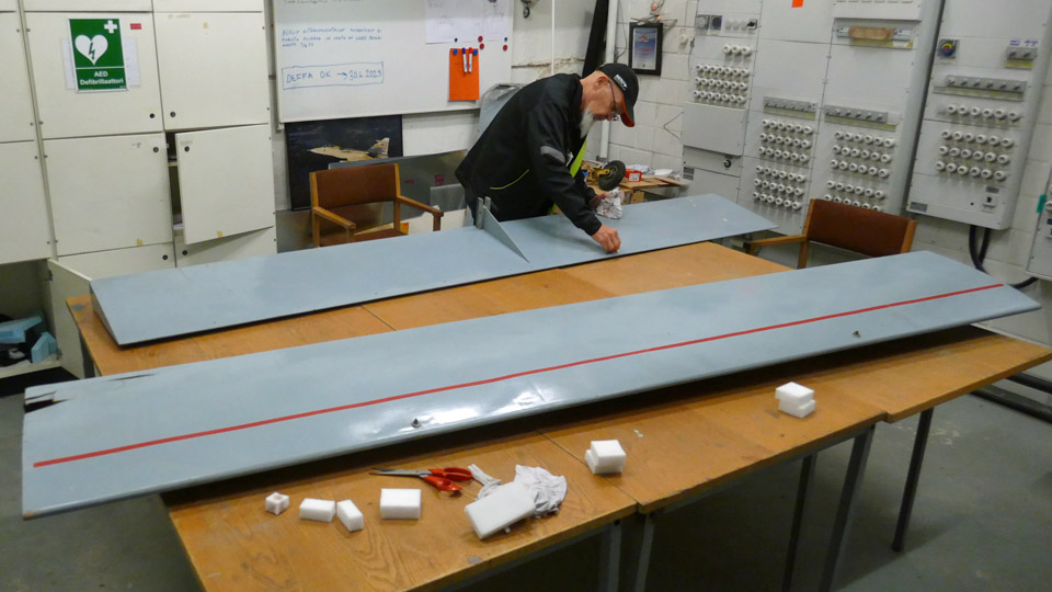
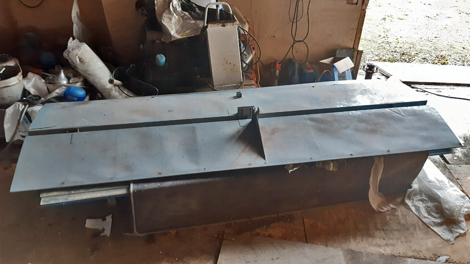
Covering of Ressu's (Snoopy) rudderMaanantai 6.5.2024 - Tuesday Club member When the preliminary tasks concerning the covering of the experimental aircraft Hietanen OH-XEA rudder had been done, the proper covering could be commenced. The rudder covering is done with cotton fabric meant for covering aircraft. The covering will be done the same way it had originally been done in the 1960s.
The covering got started by setting the metal-framed rudder on the fabric, which was spread on the table. The edge of the fabric was wrapped around the right-hand side metal tube of the leading edge and sewed onto it. The sewing was done with thin cotton thread, using a suitable curved or hooked needle.
After the fabric had been sewn to the leading edge right-hand tube, the rudder was turned over on the table, so that the metal frame of the rudder was left under the fabric. The fabric that was attached to the right-hand leading edge, was drawn over the leading edge and left-hand side to the trailing edge the of the rudder, where the lapel of the fabric was left hanging over the table edge.
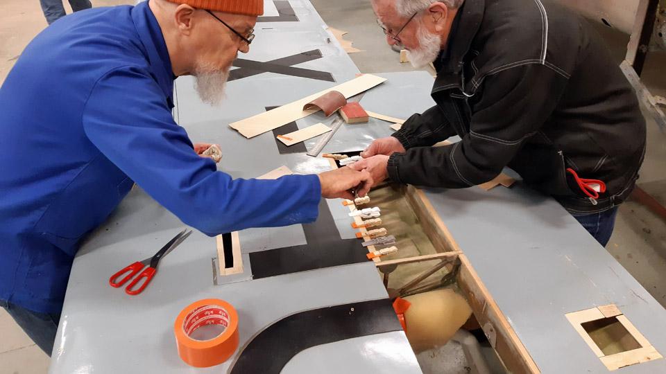
A metal bar was attached to the hem of the fabric hanging over the table edge. With the aid of the bar the fabric, resting on the left-hand side of the rudder, was tightened. At the top and bottom edges of the rudder the lapels of the fabric were tightened with small clamps to the edge of the table. When the fabric was tightened this way, the water tightening of the fabric was started. The fabric was soaked through with boiled water. When drying, the fabric shrinks a little. The proper tightening of the covering fabric will be done after the water tightening with nitrocellulose lacquer.
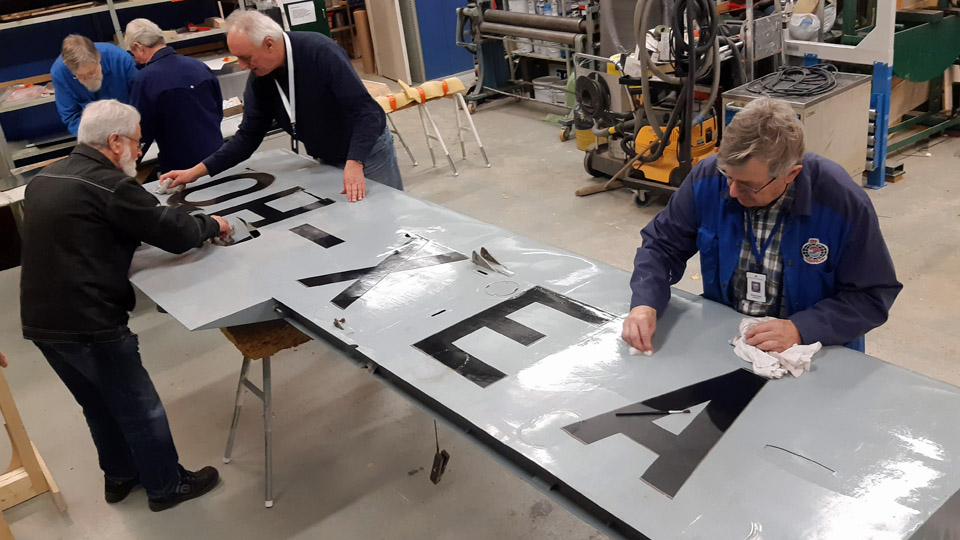
The tightening lacquering of aircraft covering fabrics is carried out in a process with several phases. The tightening lacquering is started with a 25 % thinned nitrocellulose lacquer. From that the process continues with intermittent sanding to 50, 75,100 -% nitro lacquer. After each phase the fabric is sanded free of the fuzz brought to the surface by the lacquer. From phase to phase the covering fabric will shrink more and more. The end result is a covering fabric tight as a drum head. The sufficient degree of tightening is easy to verify by tapping the surface. It’s customary to pigment or colour red the lacquer with iron oxide powder. This will help to recognize which area has been dealt with the lacquer and which not.
When the water-soaked fabric on the left-hand side of Ressu’s rudder had dried, 25 % thinned NC-Speed nitrocellulose lacquer was applied on the surface of the fabric. As a thinner NC-Speeds’s own Thinner-8 was used. The lacquer was tinted red with red iron oxide powder. After the lacquer had dried, the weights were detached and the rudder was turned around, after which the unlacquered side of covering fabric was drawn tightly under the right-hand side of the rudder. The lapel of the fabric was sewn to the leading edge of the right-hand side metal tube, i.e. the same, where the lapel of the fabric had been sewn in the first place. The covering fabric was now around the rudder like a bag.
Now the right-hand side fabric of the rudder in its turn was water-soaked. After that this side, too, was lacquered with 25% NC-Speed tightening lacquer. After the lacquer had been dried, the rudder’s lower edge, triangular shaped in cross section, was covered by sewing the lapels of the fabric onto the tubes in the rudder’s lower edge.
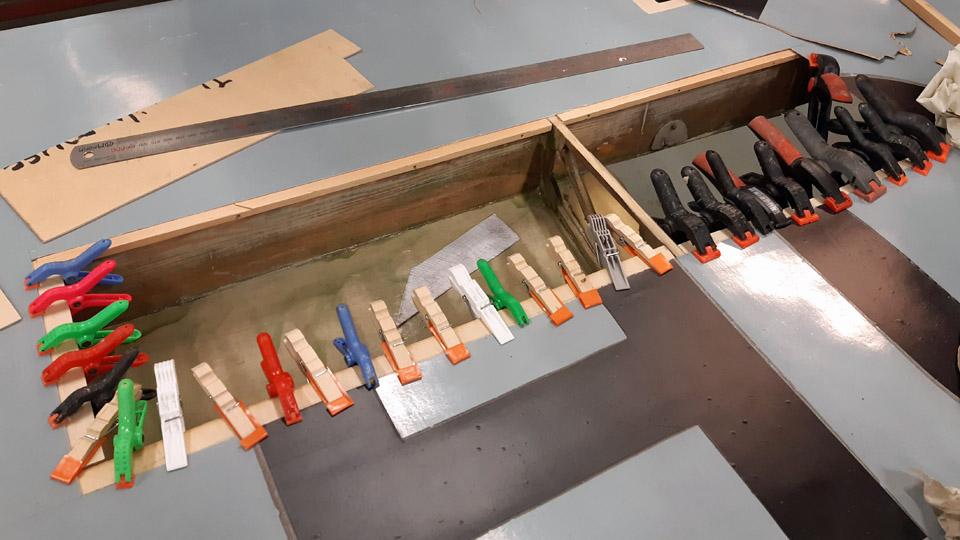
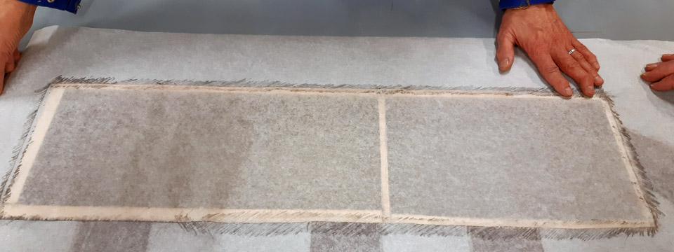
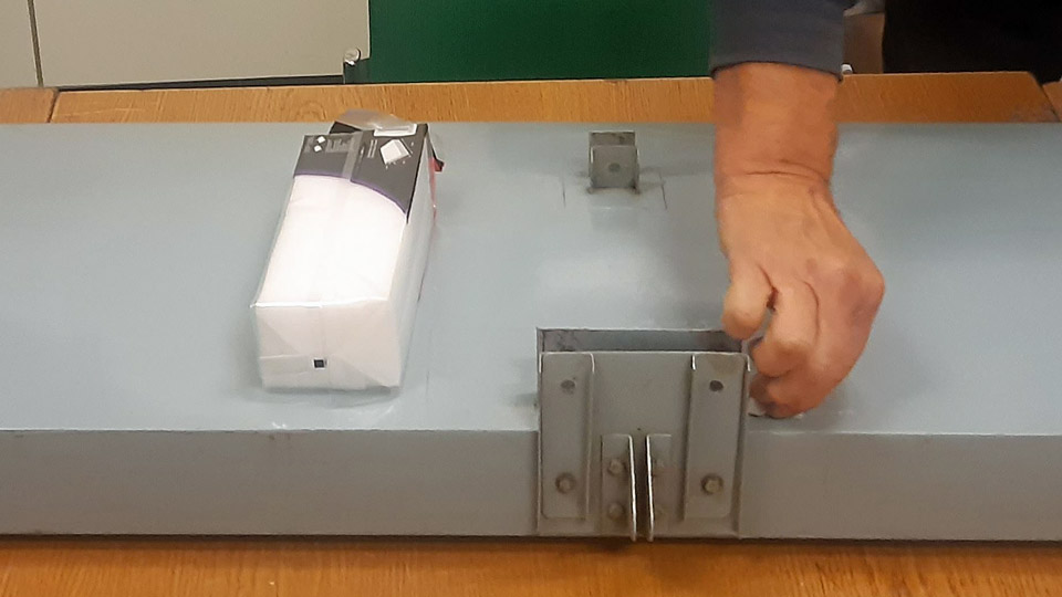
The tightening of the covering fabric continued with applying a second layer of 25 % lacquer on the rudder surfaces. Because the fabric didn’t start to tighten in the manner we had hoped, the rudder was lacquered a third time over with 25% lacquer. From this point on we advanced in stages to three times applied 50% and twice applied 75% NC Speed lacquering. In this manner a sufficient level of tightness was achieved, so that the fabric strips protecting the stiches of the covering fabric at the edges of the rudder can be fastened. The protecting strips will be glued to the leading, upper, and bottom edges of the rudder. No strip will be needed at the trailing edge because there’s no seam in the fabric there. Of course we could glue a strip there, too, because it would make it more resilient.
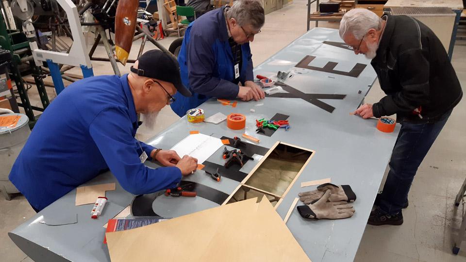
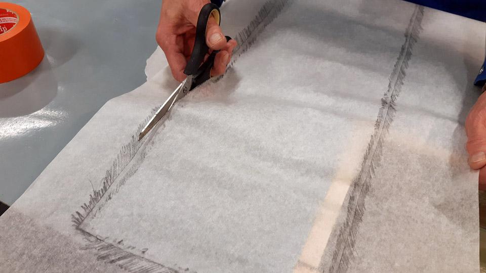
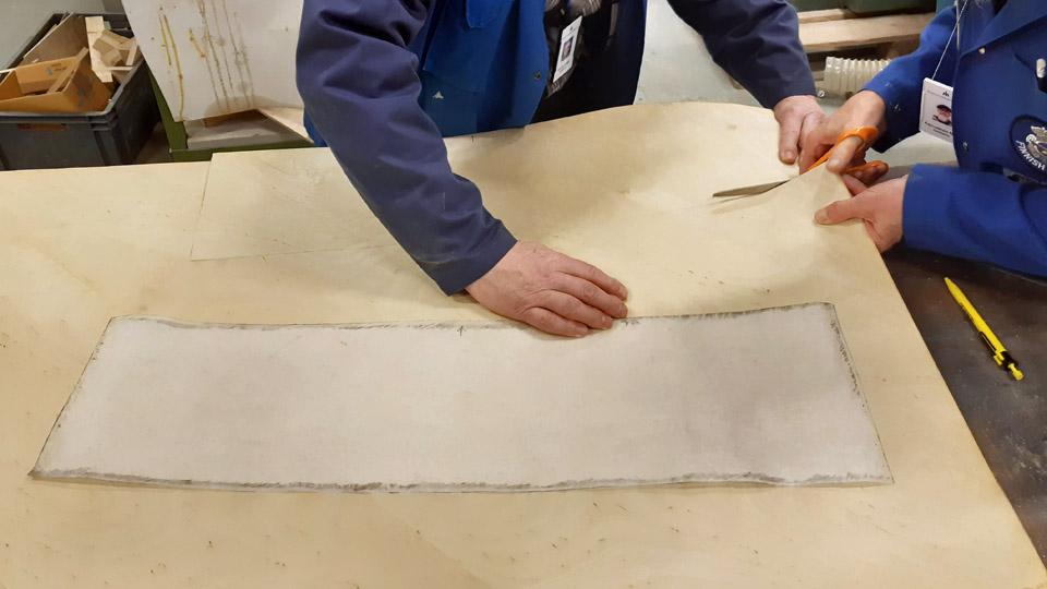
The protective strips were cut off the same covering fabric with which the rudder was covered.
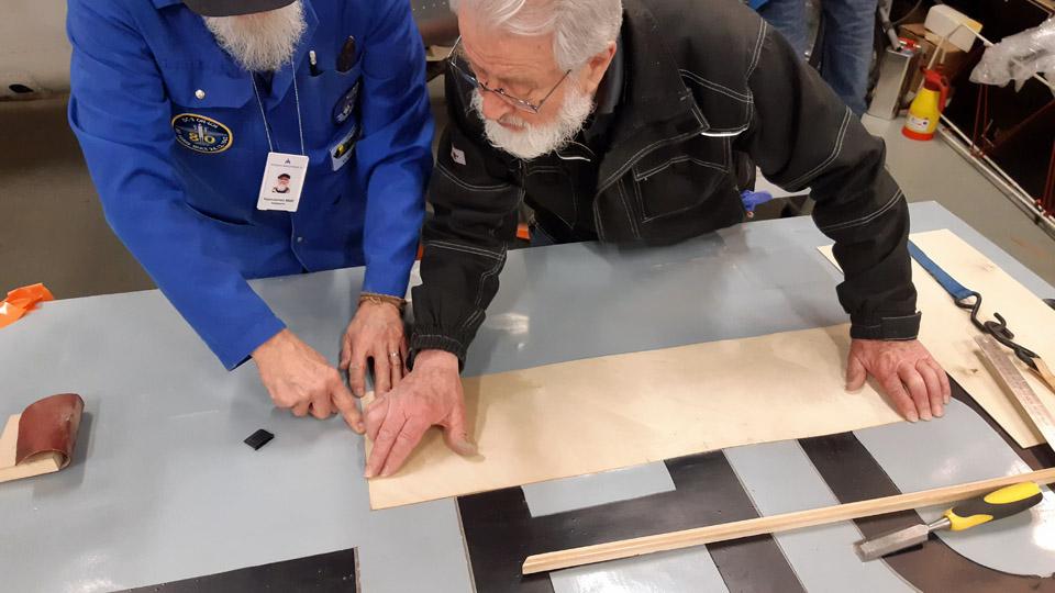
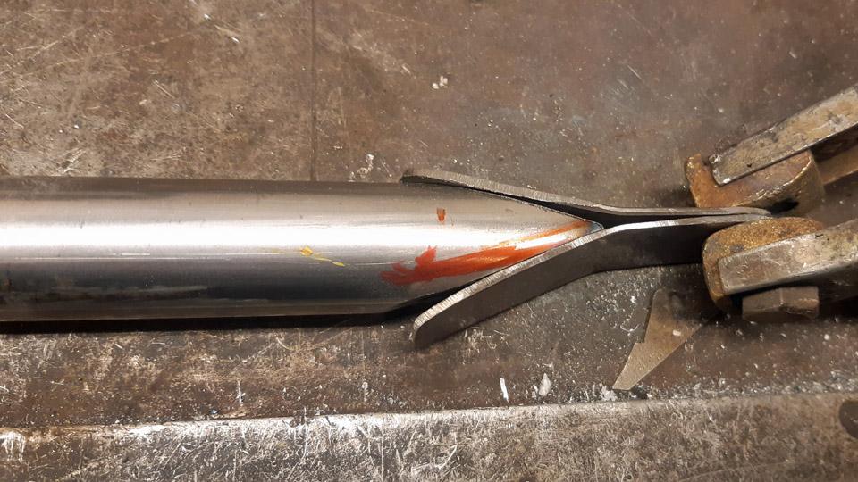
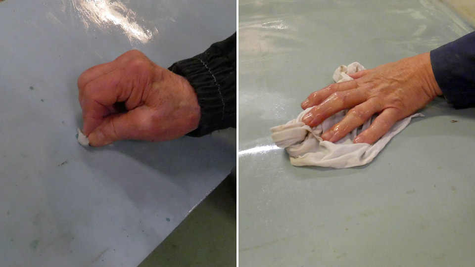
The cutting was done with serrated zig-zag scissors. The serrated edge of the protective strip will stick better to its base, i.e. the lacquered surface of the covering fabric compared to the straight edge.
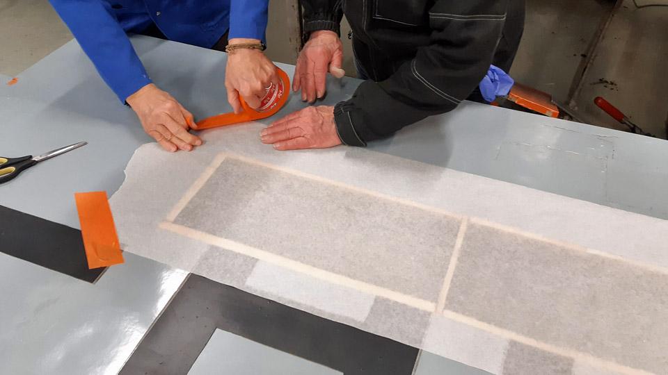
The protective strips were glued to the rudder with 75% nitrocellulose lacquer. First the area of the protective strip was lacquered, after which the strip was pressed onto the wet lacquer. The strip was applied with lacquer so that it became thoroughly soaked with lacquer. The strip was pressed against is base and brushing away air pockets or bubbles from under the strip. At the same time it was made certain that the serrated edges were tightly glued to the surface of the covering fabric.
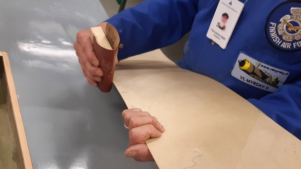
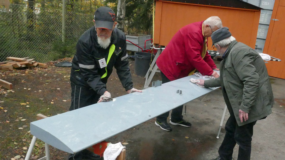
After the strips had dried, their surfaces were sanded smooth paying attention especially to the serrated edges. The lacquering and sanding were repeated three times, after which the protective strips and especially their serrated edges were worked so smooth, that feeling with your finger gave you no sensation of the strip edge on the surface of the covering fabric.
After fastening the protective strips, the whole rudder was lacquered once with 100% nitrocellulose NC Speed lacquer. The covering fabric of the rudder had now reached the stage where it was as tight as a drum head and thus ready for painting. According to Ressu’s original colour scheme it will be light bluish grey. Photos by Lassi Karivalo. Translation by Matti Liuskallio. |
|
Avainsanat: aviation history, restoration, Tuesday Club, Hietanen HEA-23b, OH-XEA, "Ressu" |
The Ressu (Snoopy) rudder covering preliminary work assignmentsSunnuntai 21.4.2024 - Tuesday Club member The IMY Tuesday club has continued its work with the Snoopy (Ressu). Planned and built by the Hietanen Brothers from Turku, the mixed structure experimental aircraft Ressu from the 1960s is next in line for the rudder’s canvas covered steel tube structure to be restored.
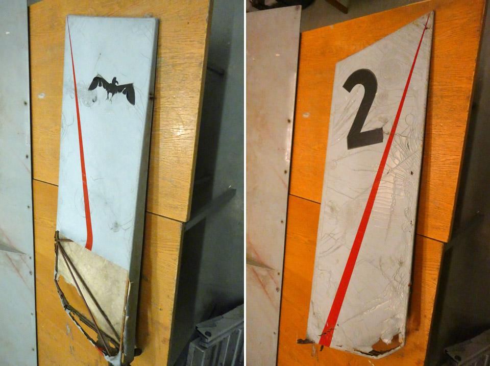
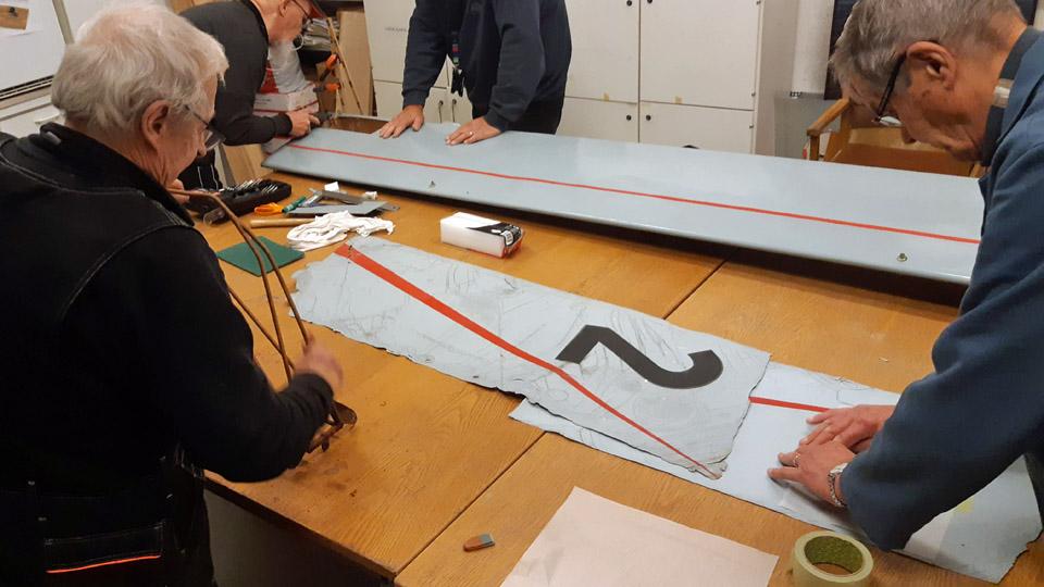
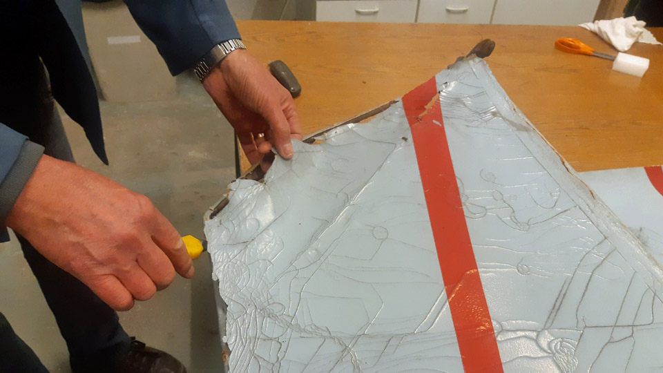
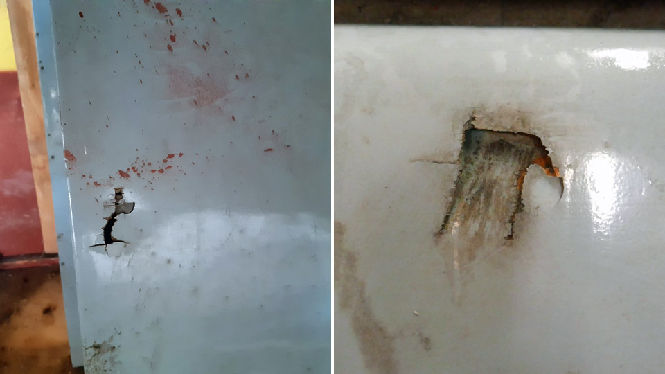
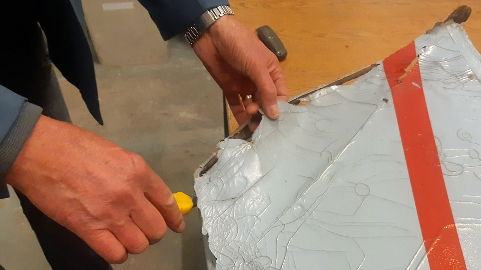
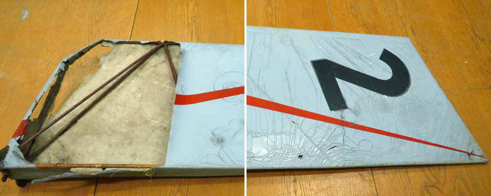
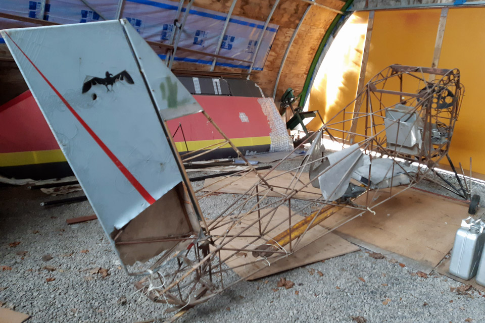
For the restoration the rudder was detached from the fuselage. The fabric covering was in a fragile shape, and the paint finish of the canvas badly crackeled. On the left-hand side the covering is fairly intact, but on the right-hand side a large piece of covering is missing on the lower edge. From this unexpected opening it could be seen that the covering canvas had been sewn onto the rudder frame outer tubes only, but not onto the cross tubes. The outer ring metal tubes had been covered with 20 mm wide cotton edging ribbon, by winding it the tightly along the tube. This was a common way to avoid the covering fabric to be attached to form a direct contact with metal. The fabric, that was sewn to the metal structure, had been tightened drum tight with nitrocellulose lacquer, after which the surface had received a light blue coat of paint. Finally the rudder had been treated with red speed stripes, a black number 2 and a bird figure.
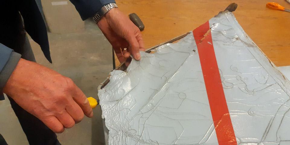
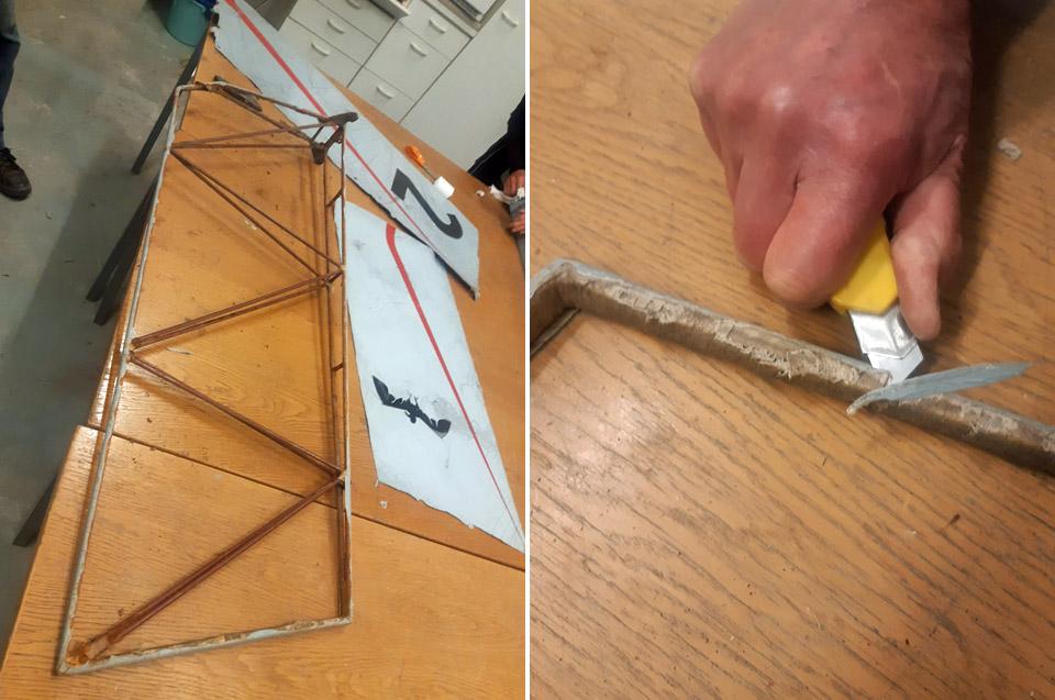
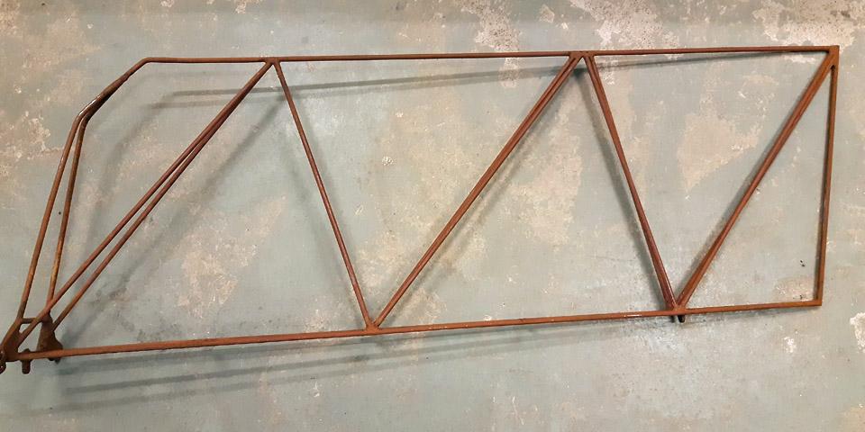
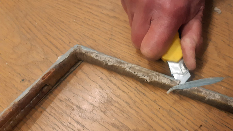
Because the Ressu’s rudder covering fabric was in a bad shape and partly broken, we decided to cover it completely anew, complying the old manner of doing it, however. The old covering fabric had to be detached from the steel frame of the rudder by cutting it off with a knife, because the fabric had glued itself tightly to the edging ribbons around the tubes. After detaching the covering fabric, the edge ribbons around the metal tubes were also removed.
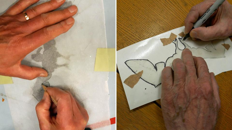
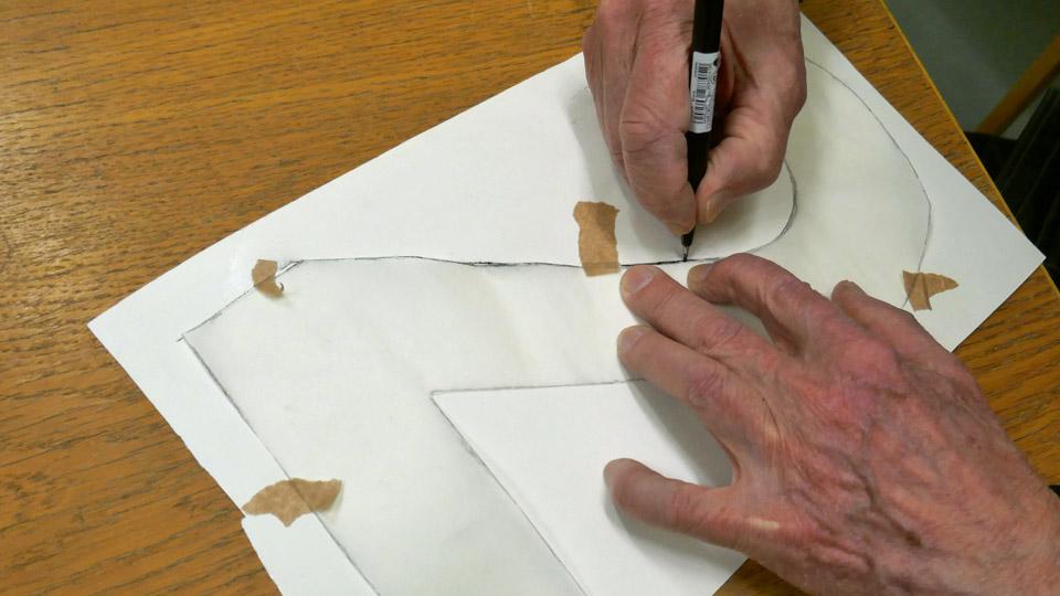
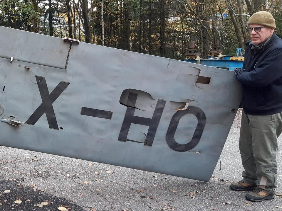
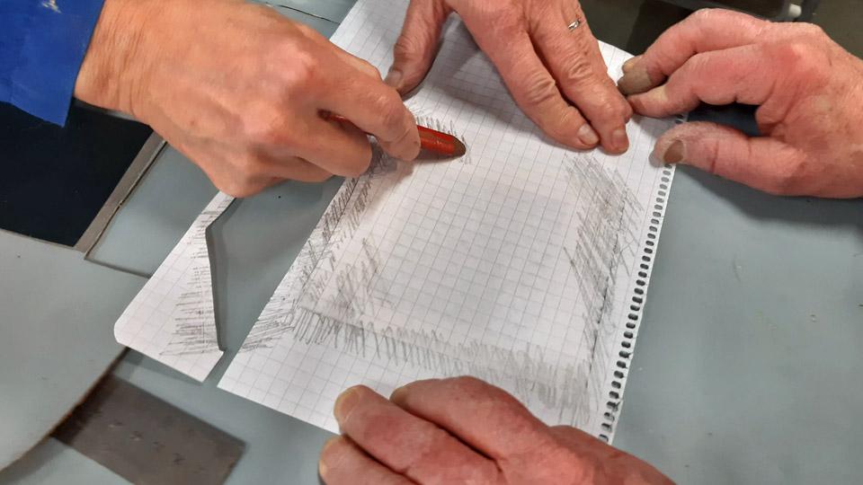
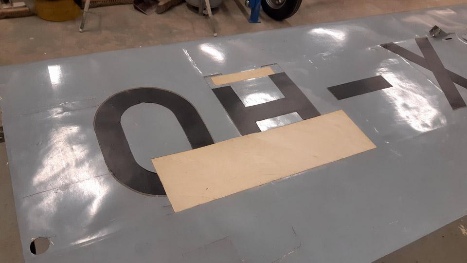
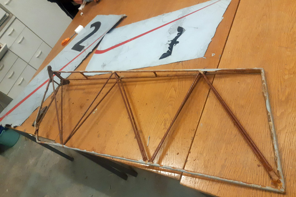
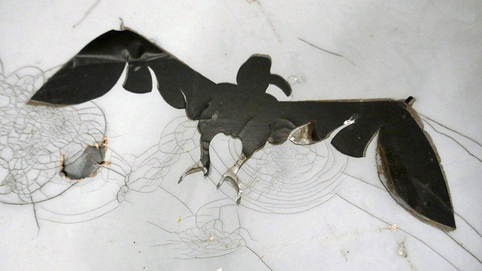
The red stripes of the rudder’s covering fabric and the left-hand side black number two and the right-hand side black bird were copied on transparent rice paper. After that the bird and the number were transferred onto sturdy cardboard to wait for the final transfer of these symbols onto black contact plastic, and their fixing onto the surface of the new covering fabric.
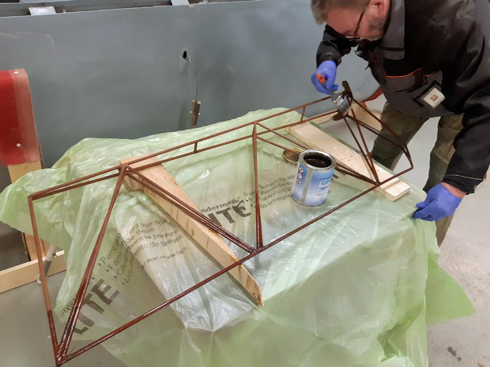
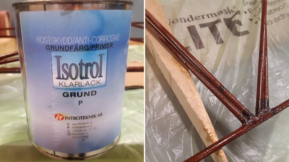
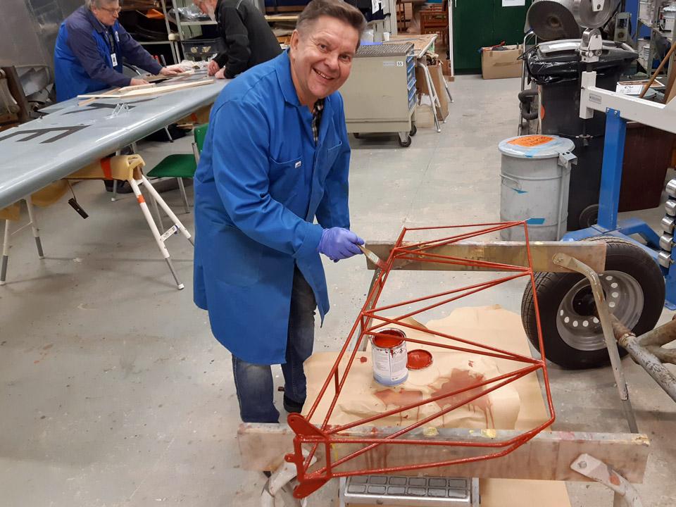
The work with the rudder’s metal structure was continued with doing away with the rust on the tube surfaces. Luckily the tubes weren’t badly rusted or corroded. The rust was sanded off with sanding paper, however, so that the tubes weren’t ground to pure metal. The transparent Isotrol-lacquer can be applied as primer even though the surface is still a bit rusty. The shielding cover of the Isotrol- lacquer will stop the rusting process. During the sanding it had been noticed that the rudder had originally been painted red. The paint had most probably been the red Ferrex, used widely in the 1960s to stop rusting.
The rudder frame structure was primed thinly with the transparent Isotrol -lacquer. Owing to the lacquer, the tube surfaces came out beautifully clear and the red paint applied on the surfaces rose up even more gloriously. After a light buffing, a layer of red Isotol paint was applied on the bright Isotrol lacquer, emulating the original red surface paint.
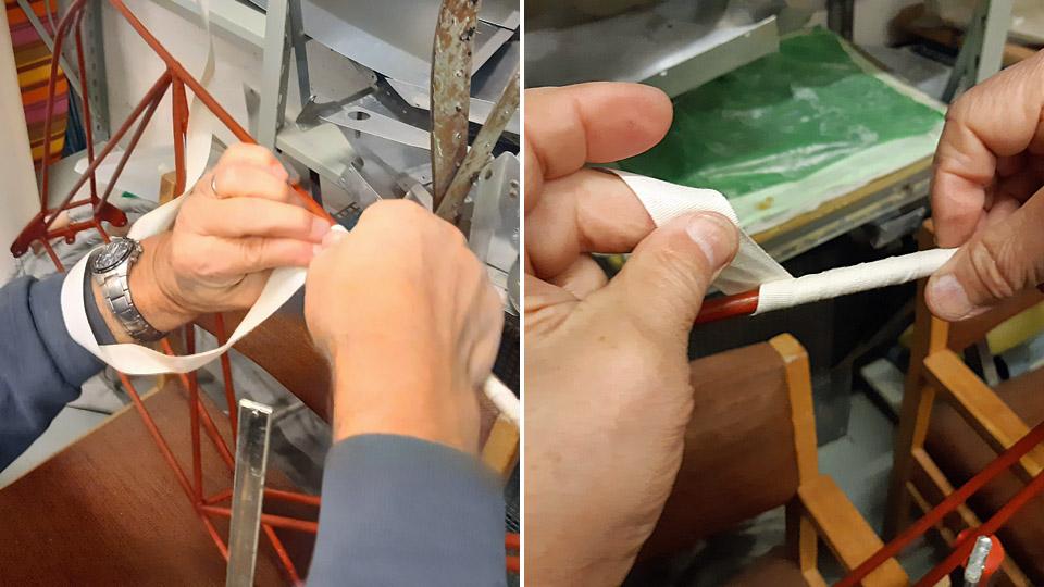
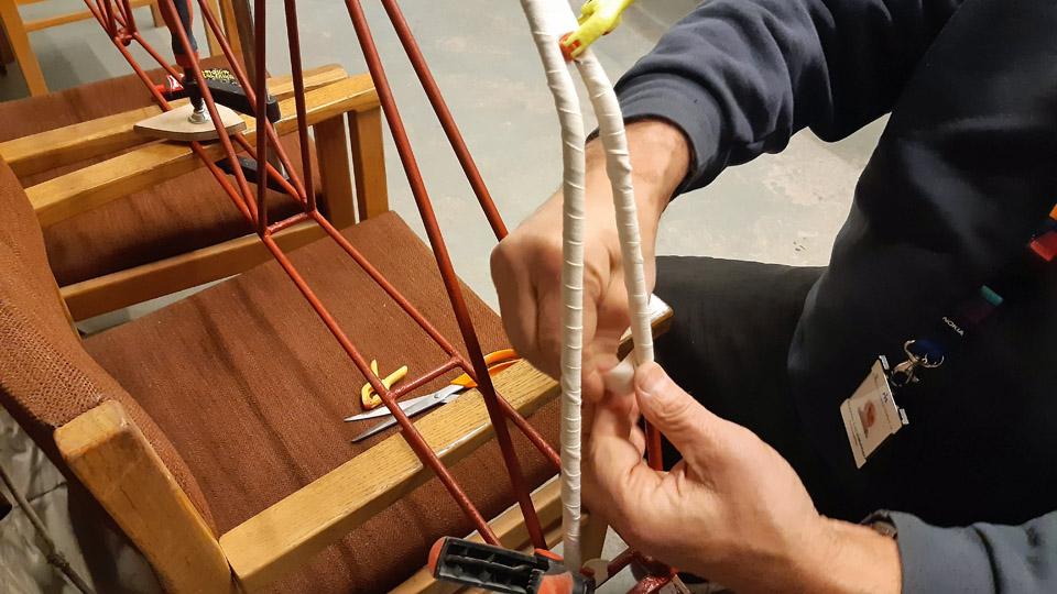
When the rudder frame had dried, we started to cover the steel tubes by winding 20 mm wide cotton edging ribbon around the steel tubes. Thus we’ll prevent, according to the original concept, the covering fabric being in direct contact with the surface of the steel tubes. By hurrying slowly we managed to wrap the cotton ribbon around the outer tubes of the frame. Ressu’s rudder in now ready to begin the fabric covering proper. Photos by Lassi Karivalo. Translation by Matti Liuskallio. |
|
Avainsanat: aviation history, restoration, Tuesday Club, Hietanen HEA-23b, OH-XEA, "Ressu" |
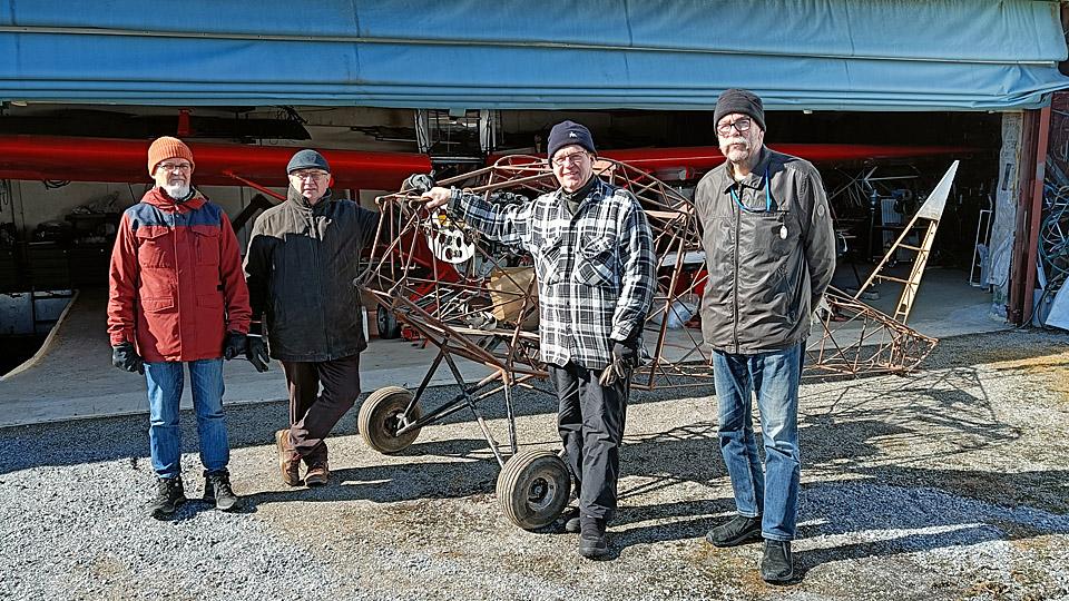
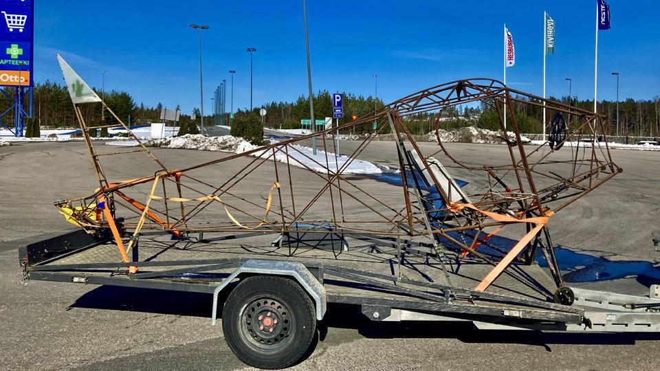
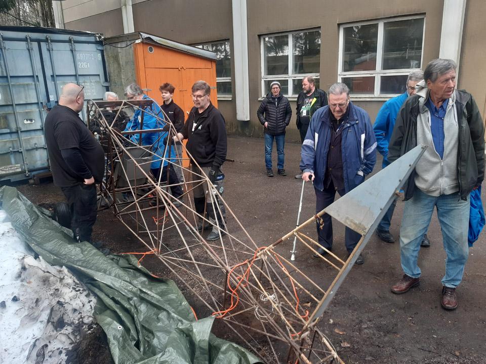
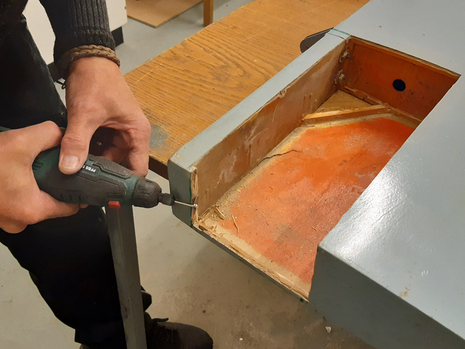
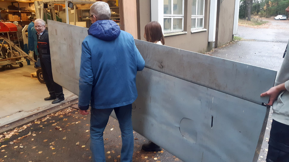
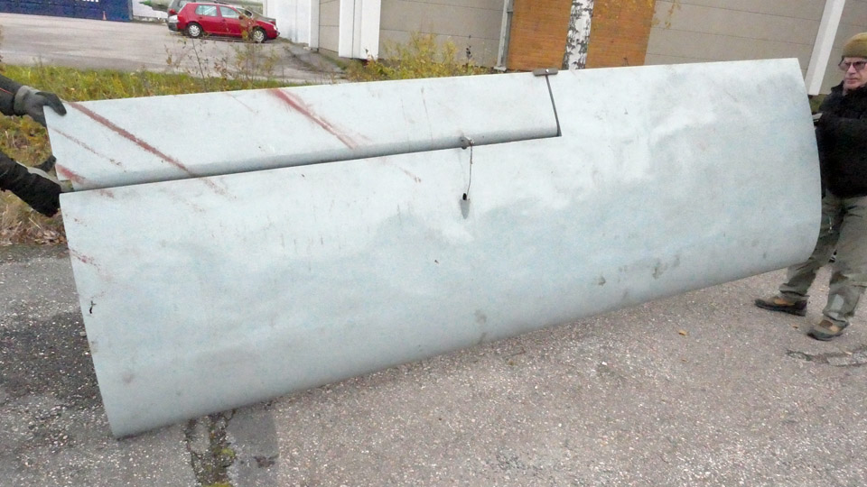
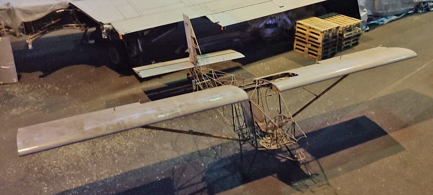
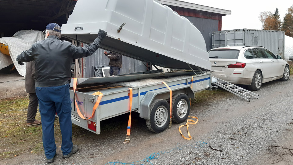
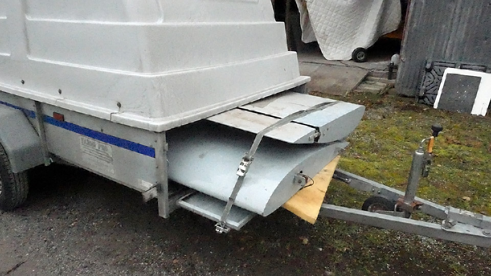
Ressu's fuselage frame moved from Lemu to VantaaTiistai 9.4.2024 - Tuesday Club member On Thursday April 4th, the Tuesday Club task force set off towards Lemu in the Turku region to fetch the OH-XEA “Ressu” (“Snoopy”) fuselage frame to Finnish Aviation Museum to be restored by the Tuesday Club. The OH-XEA is an experimental aircraft, designed and built in the late 1960s by brothers Hietanen, Esko and Ari. Since last autumn we have been working on the restoration of Ressu’s horizontal stabilizer, elevator, rudder, and wing struts. This work will be ready soon and we could pick up the Ressu’s fuselage frame from Lemu to be restored. The Ressu fuselage, stripped entirely of its fabric covering, has been stored in the hall of Martti Mattila, an aviation enthusiast from Lemu. Last autumn we fetched the Ressu’s wings and tail parts from the same place. On our way to Lemu we made a detour via Turku Airport, to Caravelle “Bluebird”, which is on display there. In Helsinki we had picked up a Super Caravelle First-Class double seat frame, which we left to the Caravelle. The aim is to build four rows of seats in the “Bluebird” cabin and an adapted group of First-Class seats. From the Airport we continued to Lemu, where we arrived soon after noon.
Photo by Martti Mattila. Martti Mattila had already prepared the Ressu fuselage frame for pick up by fastening two wheels with pneumatic tyres, borrowed from a ride-on lawn mower, on the ends of the landing gear axle and by moving the fuselage frame outside the hall. Due to the wheels the fuselage frame was easy to move. The lawn mower wheels are exactly the suitable size for Ressu. Before the fuselage fame was moved next to the trailer to be loaded, the pick-up team posed for a group photo.
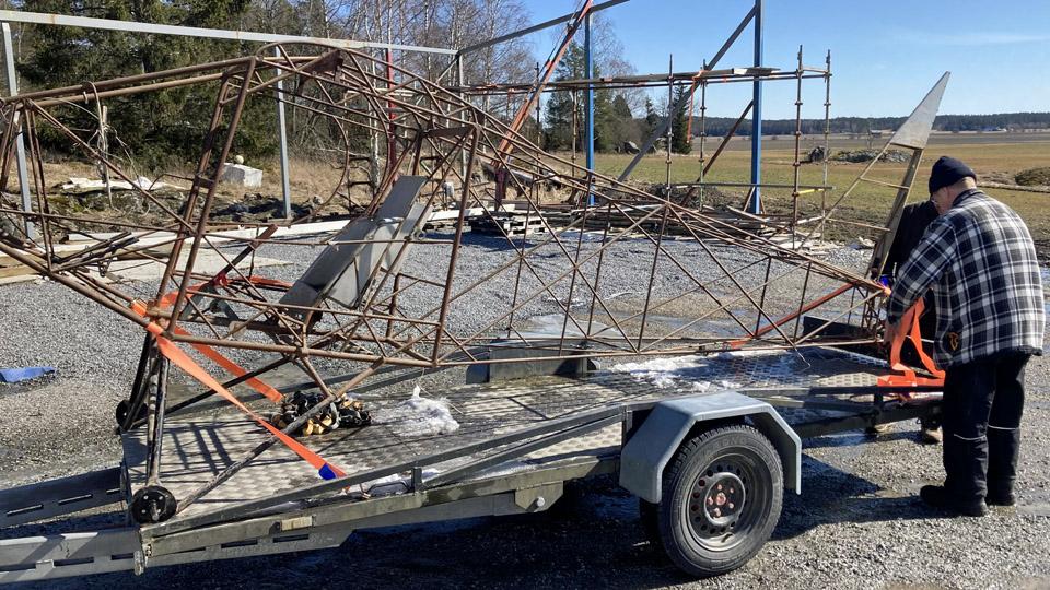
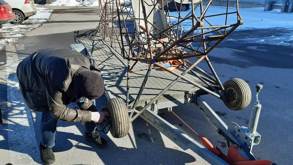
Photo by Matti Kainulainen. When the rather light fuselage frame was lifted on the trailer, we noticed that the landing gear with its wheels was too wide to fit inside the trailer sides. We solved the problem by unfastening the wheels and the landing gear fitted just nicely inside the trailer sides, and the fuselage frame rested on the trailer floor on its wheel flanges.
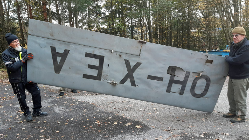
Photo by Matti Kainulainen. We fastened the fuselage frame on the trailer with the nose of the aircraft facing forward. The trailer we had at our disposal was long enough to hold almost the whole length of the Ressu’s fuselage frame. The tail reached just slightly over the tailgate. The fuselage frame was secured tightly on the trailer, front and aft, using cargo straps. We topped up our cargo by adding a security banner on the tail. We also loaded the rest of the Ressu stuff from Mattila’s hall, such as the cockpit plexiglass windows and the seat belts. Many thanks to Martti Mattila for accommodating Ressu and its parts in his hall since last June.
Photo by Matti Kainulainen. We spent some time with Martti Mattila, listening to him talking about his ongoing aircraft engine project. Based on what we heard, we can say that Mattila is a person with multiple skills when it comes to aircraft engines and aircraft in general. He has designed and built an aircraft and he also owns an airworthy engine-Lerche.
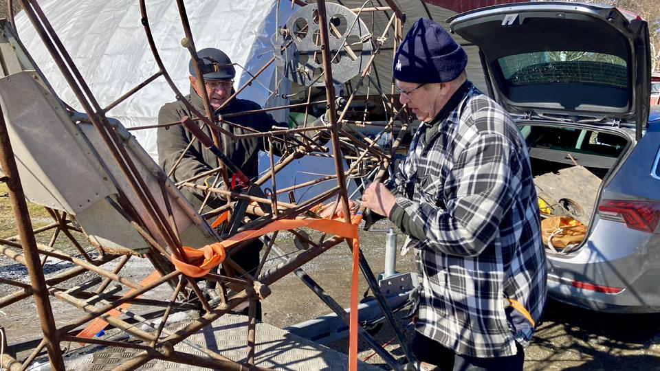
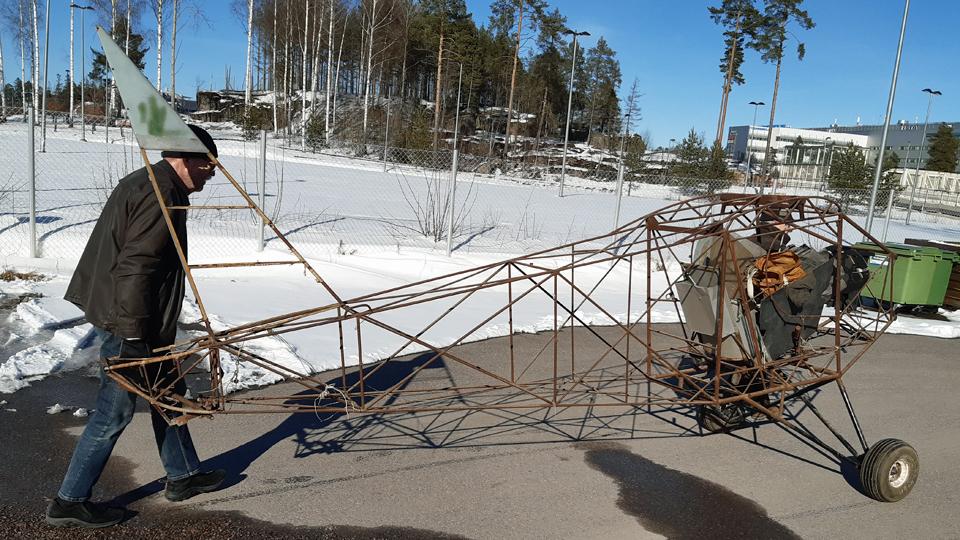
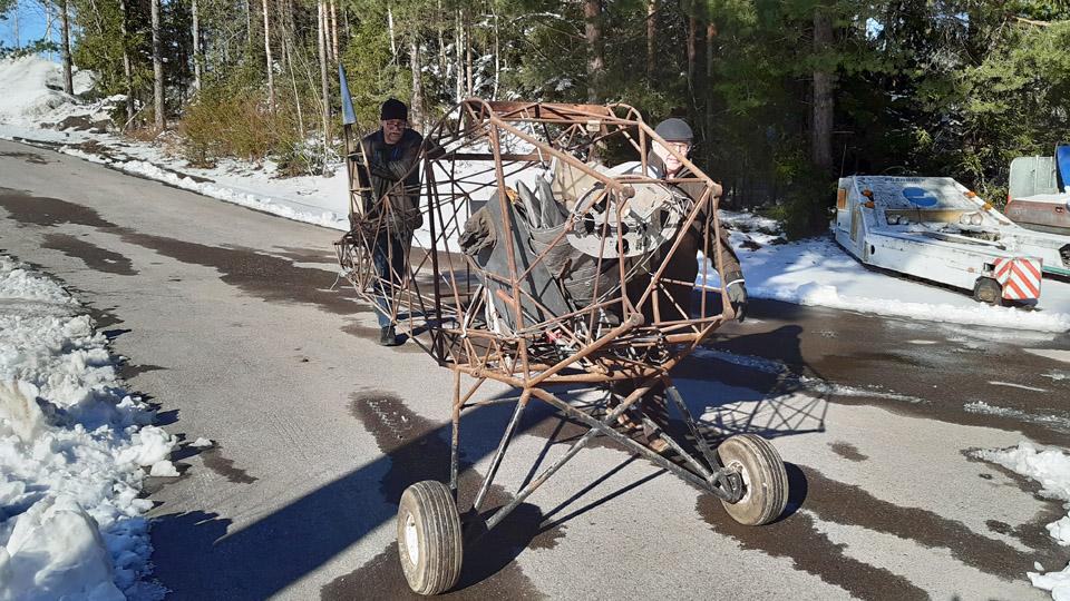
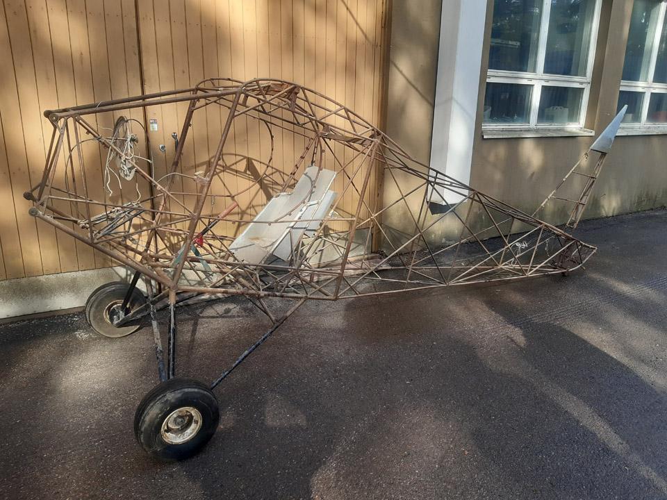
It was time to head back to Vantaa and the Finnish Aviation Museum, where we arrived late in the afternoon. On the museum yard we unfastened the cargo straps from Ressu’s fuselage frame and reassembled the wheels on the landing gear. Then we lifted the fuselage frame from the trailer on the asphalt-covered museum yard and pushed it on its wheels in front of the restoration workshop. As the Ressu’s fuselage frame will remain outside for the time being, we wrapped a tarpaulin around it to protect it from rain.
The Ressu’s fuselage frame is now ready to face the restoration procedure of the Tuesday Club. The first actual work item will be to clean the rusty frame tubes of the fuselage frame, stripped of its fabric covering. Then the tubes will be painted with protective Isotrol paint. Photos by Lassi Karivalo except if otherwise mentioned. Translation by Erja Reinikainen. |
|
Avainsanat: aviation history, restoration, Tuesday Club, Hietanen HEA-23b, OH-XEA, "Ressu" |
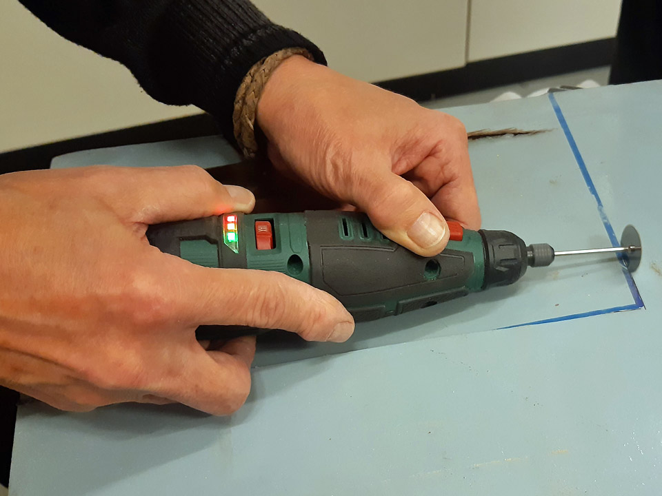
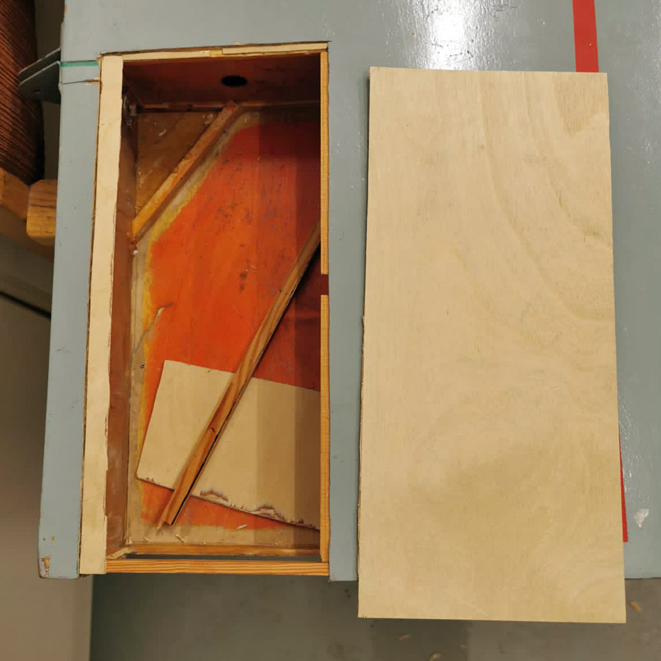
Damages in the Ressu (Snoopy) plywood covering repairedTiistai 12.3.2024 - Tuesday Club member The restoration of the experimental aircraft (OH-XEA) “Ressu” has so far concentrated on the work with repairing the holes and damages in the plywood covering of the wing halves, ailerons, horizontal stabilizer, and the elevator. This job has now been finished as far as patching goes.
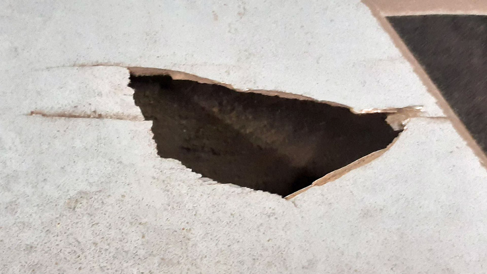
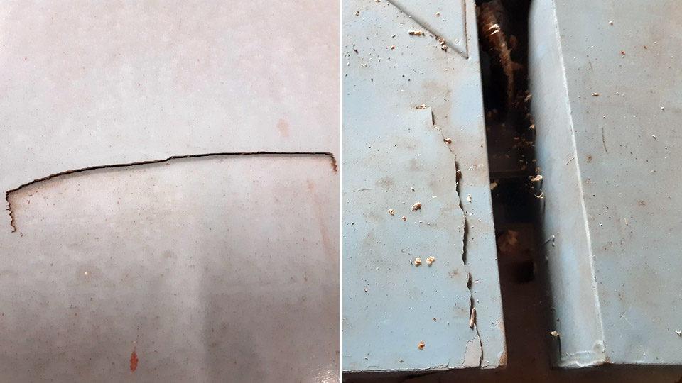
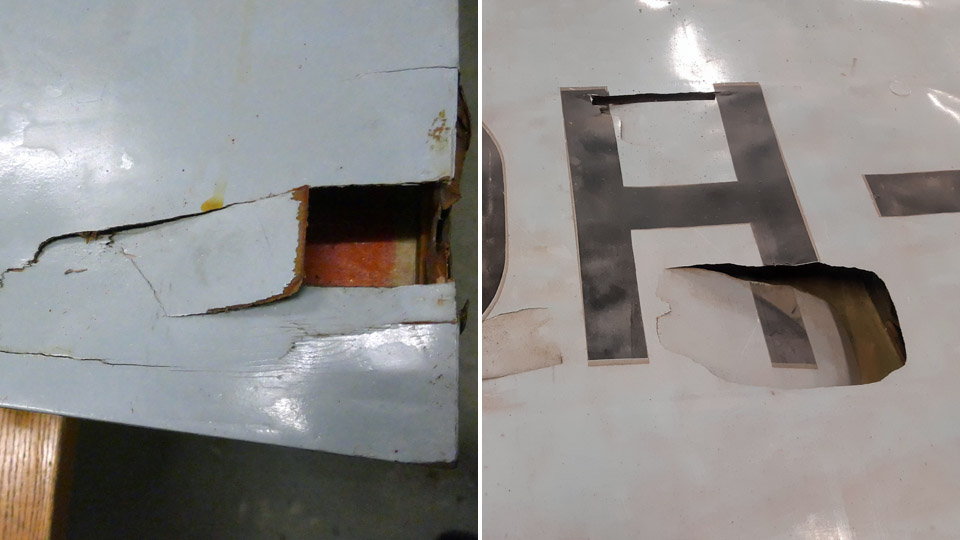
There were about twenty holes and damaged areas in the plywood covering. Part of them being tiny pinpricks, but some were damages measuring tens of centimetres. As patching material, 0,9 mm aircraft plywood was used. To patch small holes, Ressu’s original plywood with a coating of paint was used. We obtained it in connection with clearing the large damaged areas in the wing. In patching the holes in the Ressu plywood covering, we followed the same proven method throughout. In this blog the patching of a largish damage on the lower surface of the left-hand wing will be presented as an example.
A hole, or an area of a larger damage, was sawn open to a square or rectangular shape. In sawing, a “Kugihiki”, or a so-called Japanese saw was used, which is an excellent tool for sawing thin plywood. Supporting battens were glued under the sawn edges, so that about 1 cm protruded from the inside of the opening. The plywood patch to cover the opening will be glued on these supporting battens.
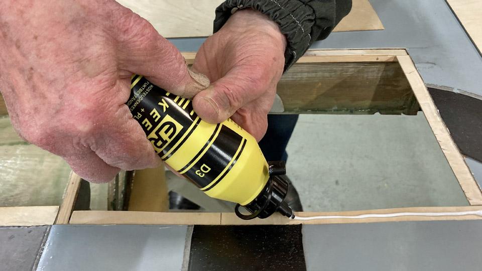
For gluing the supporting battens and the plywood patches, moisture resistant Erikeeper Plus or Casco Outdoor glue for wood was used. Before gluing the support battens, the protective lacquer was ground off the edges of the underside of the covering plywood. Thus the glue sticks better on the underside of the covering plywood. The support battens were pressed onto the edges of the underside covering plywood with small clamps. Work was also in progress with other holes in the wings, simultaneously with this large opening underside the left-hand side wing.
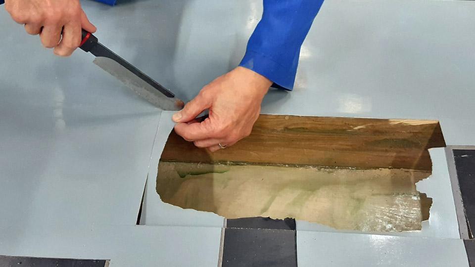
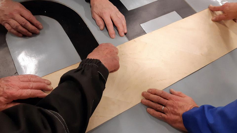
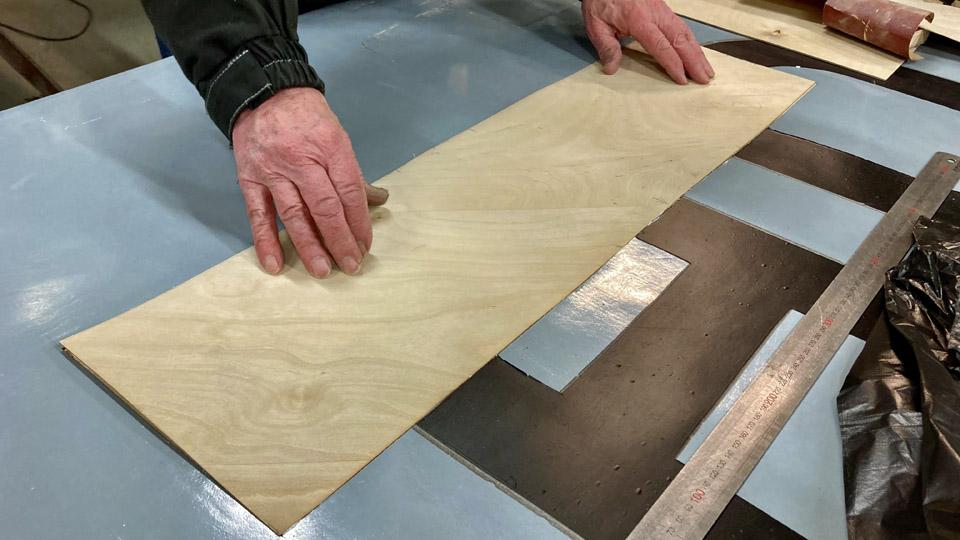
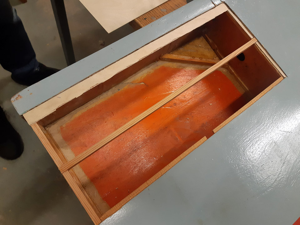
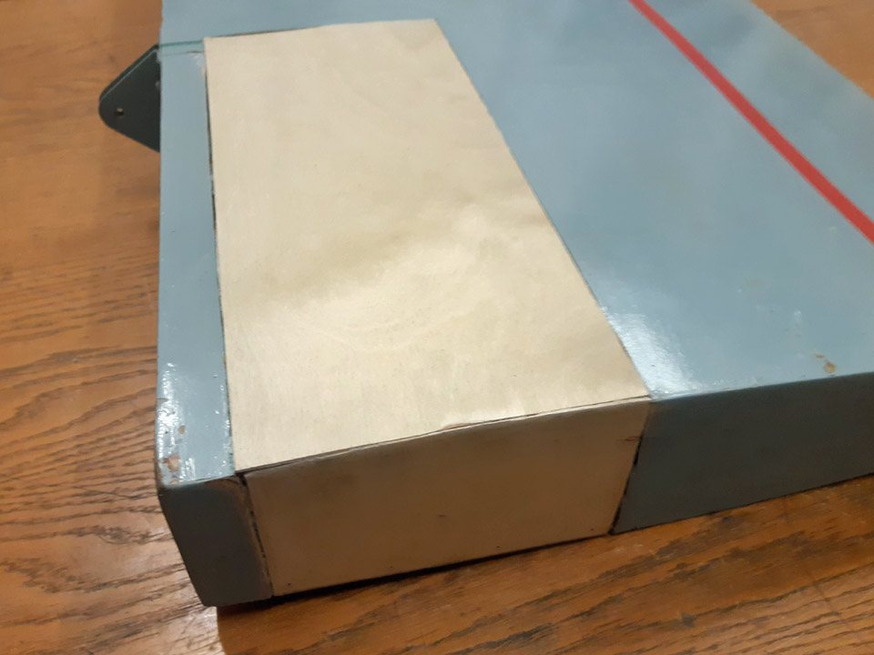
After the glue had dried, a sheet of thin paper was fastened over the whole opening to be patched. The plywood edges of the plywood opening were “smudged” with a pencil so that it became visible on the paper, thus producing an image of the edge line of the opening. The paper was cut along the now visible opening edge in the plywood. So we had a model to cut the right size of a patch. The paper was superimposed on a sheet of plywood and, hey presto, after this model a plywood patch we needed was cut out of the sheet.
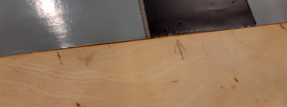
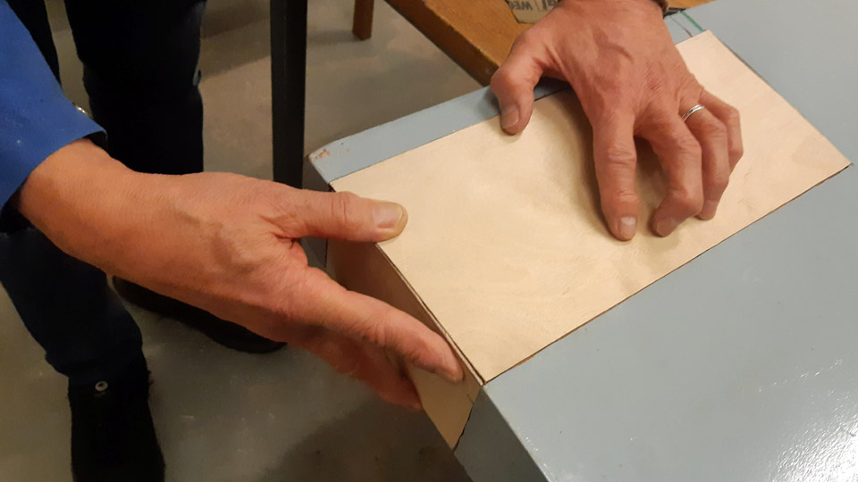
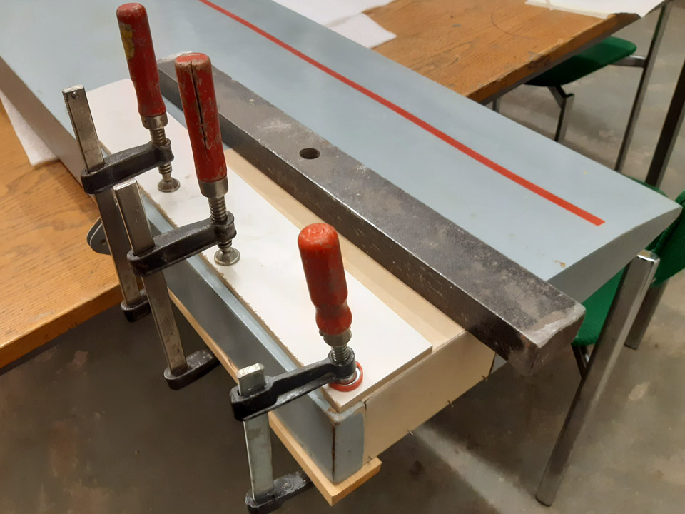
The cutout piece of plywood was fitted in place on the support battens. We marked with arrows the places where the plywood patch still needed filing at the edges, to get the patch press itself in a butt-joint manner against the edges of the opening. When the plywood was in place, glue was spread on the support battens, and the plywood was pressed against the battens.
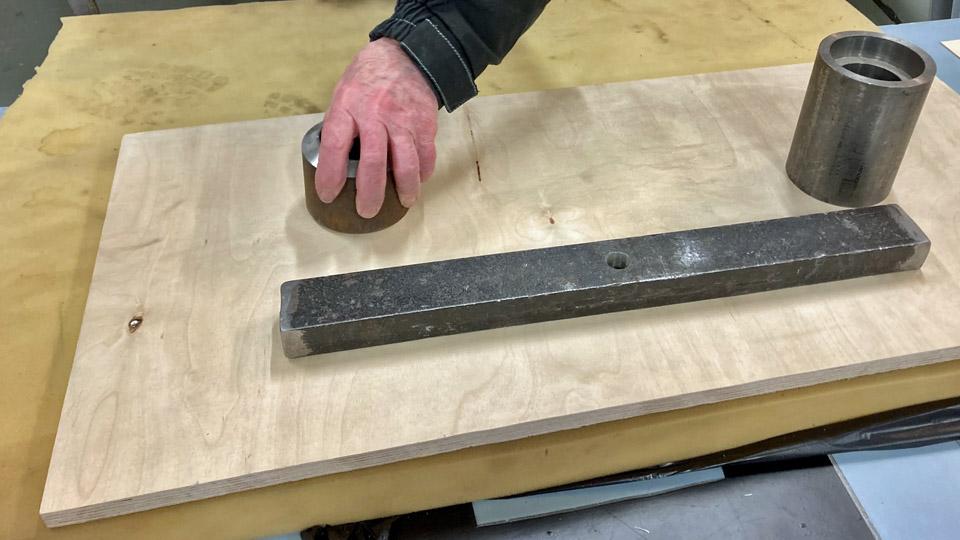
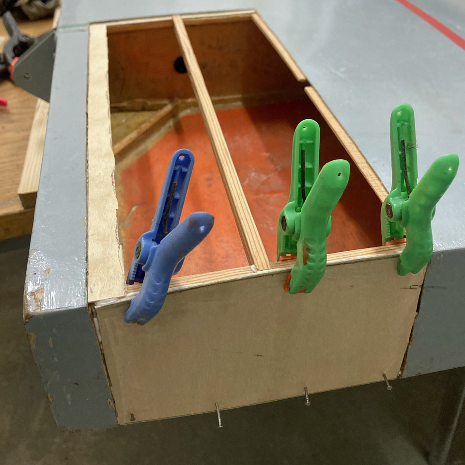
The gluing of the plywood patch was secured by putting a sturdy plywood sheet on the patch and iron weights piled on it. At the lowest a sheet of foam rubber was placed to distribute the weight evenly.
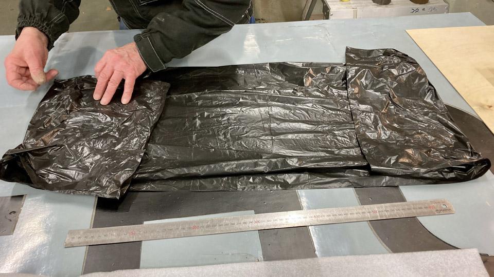
Before laying the weights, a layer of protective plastic was spread over the patch, to prevent extra glue from seeping off the seams of the plywood patch and possibly sticking to the foam rubber sheet. When both the foam rubber sheet and the sturdy plywood sheet were in place, iron weights were piled on the plywood sheet. We noticed after the glue had dried and the weights and the plywood sheet were removed, that the plywood patch had settled very neatly in place. Photos by Lassi Karivalo. Translation by Matti Liuskallio. |
|
Avainsanat: aviation history, restoration, Tuesday Club, Hietanen HEA-23b, OH-XEA, "Ressu" |
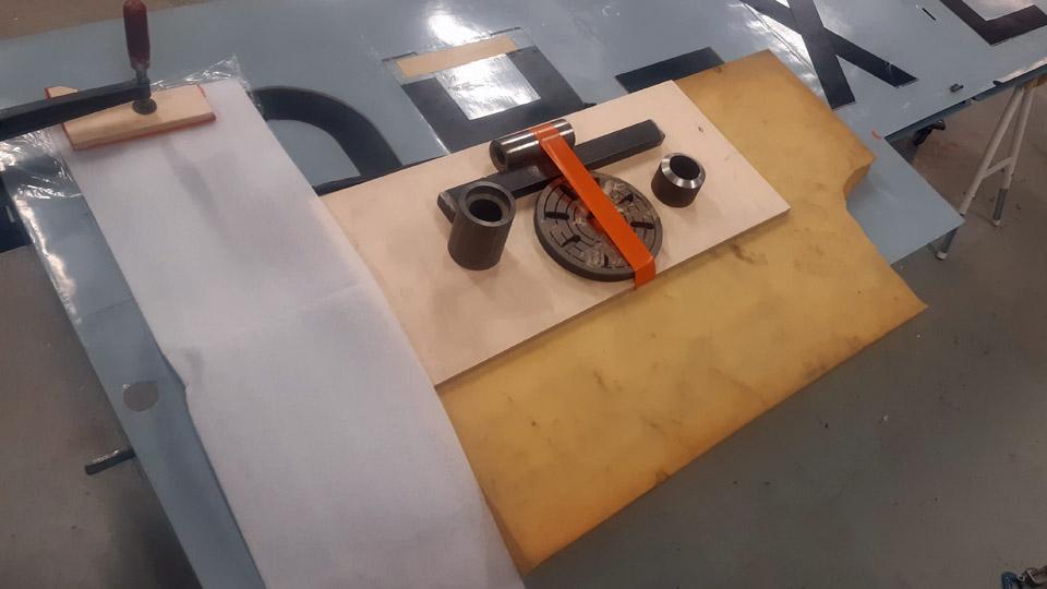
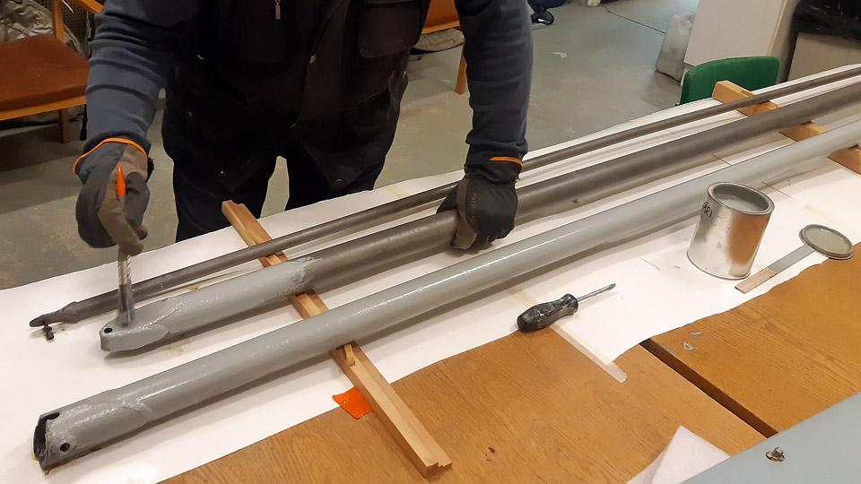
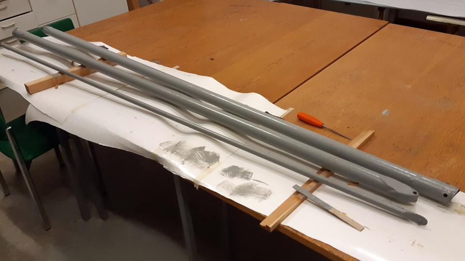
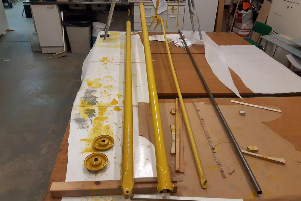
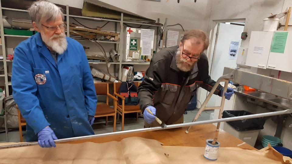
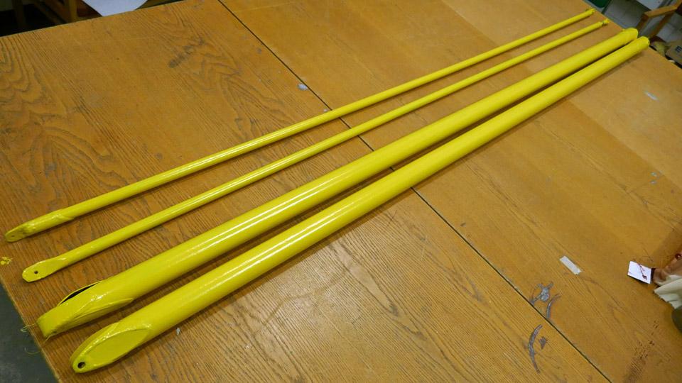
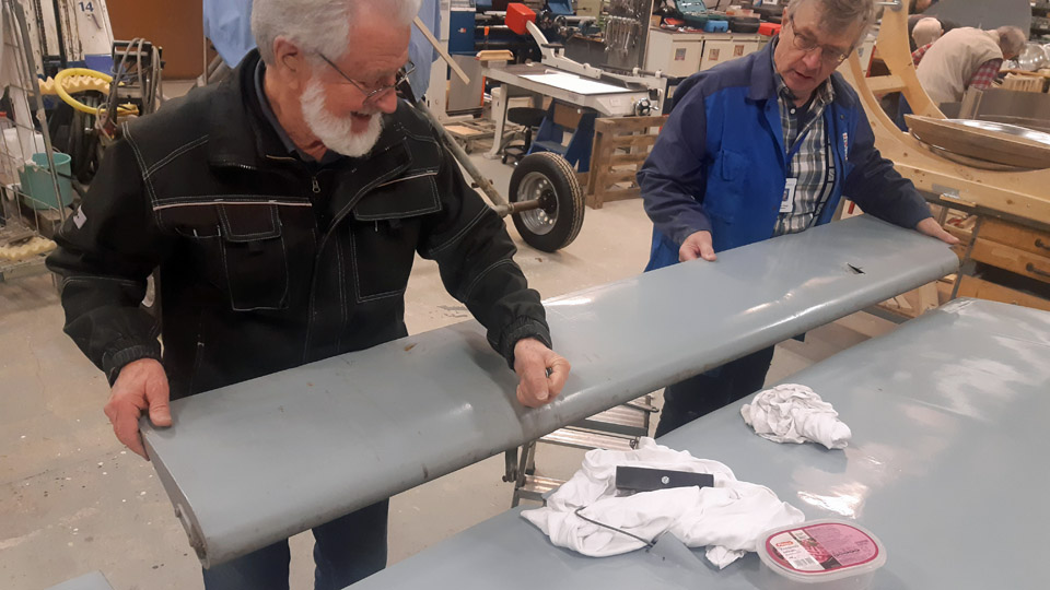
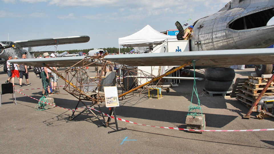
Restoration of the Ressu (Snoopy) experimental aircraft?s wing struts and building the missing oneLauantai 17.2.2024 - Tuesday Club member The restoration of the Ressu aircraft’s wing struts is completed. The aircraft was designed and built by the brothers Hietanen from Turku in the 1960s. Originally registered OH-HEA, the aircraft was registered as an experimental aircraft with the registration OH-XEA in 1969.
The wing halves of the high-wing Ressu are supported with two wing struts fastened to the fuselage lower edge. The front strut has been made of 50 mm and the rear strut of 20 mm thick steel tube. Both the front struts have remained, but only one of the rear struts. These three struts had been in storage inside the bare fuselage frame, which had no covering. The rusty struts were restored yellow according to the original paint scheme and the missing strut was built.
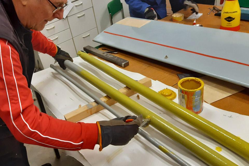
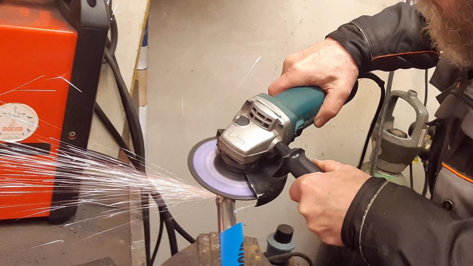
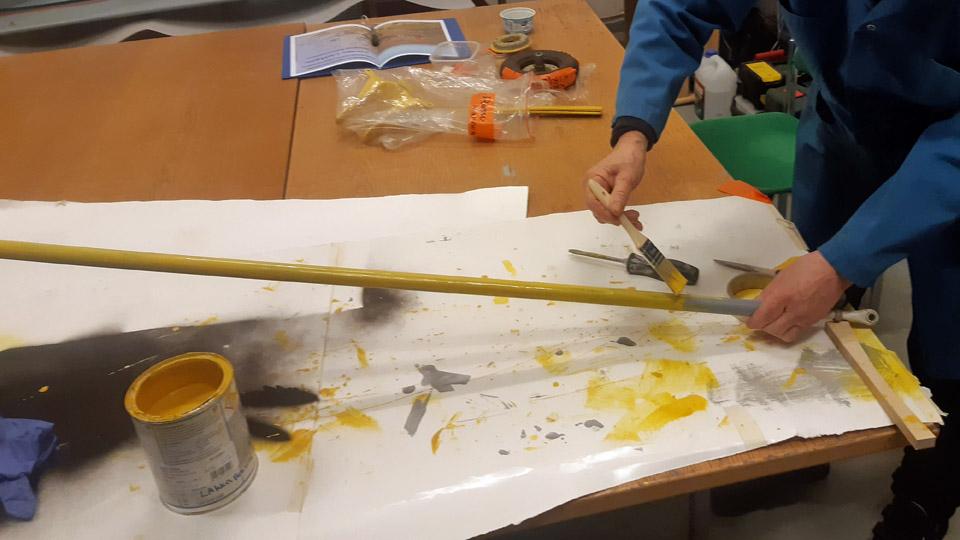
The restoration of the struts was started by taking them to be sand blasted at Taximo Oy in the Tattarisuo area in Helsinki. The sandblasted struts were dealt with a transparent anti-rust Isotrol-lacquer immediately after the sandblasting. The struts were primed with light grey Isotrol-paint of the shade RAL 7005. The light grey primer worked well for the yellow finishing paint of the struts.
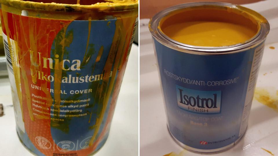
As the yellow finishing paint we used at first the Tikkurila UNICA outdoor furniture paint with RAL 1023 as the shade. The yellow paint had poor coverage, which we knew in advance. To replace the UNICA, a corresponding yellow Isotrol paint of the similar shade was chosen for the second coat of paint. The yellow pigment of the Isotrol paint has a better coverage, which was noted when painting the struts. They were painted with the yellow Isotrol three times over, so
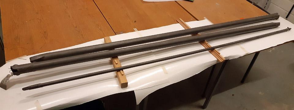
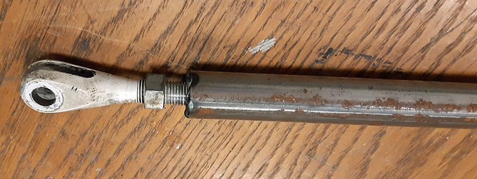
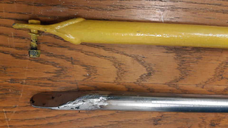
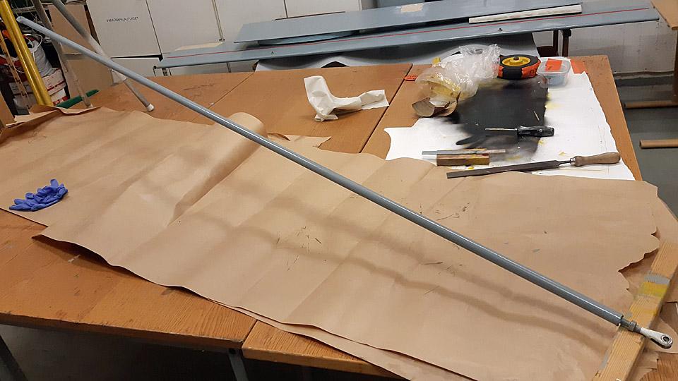
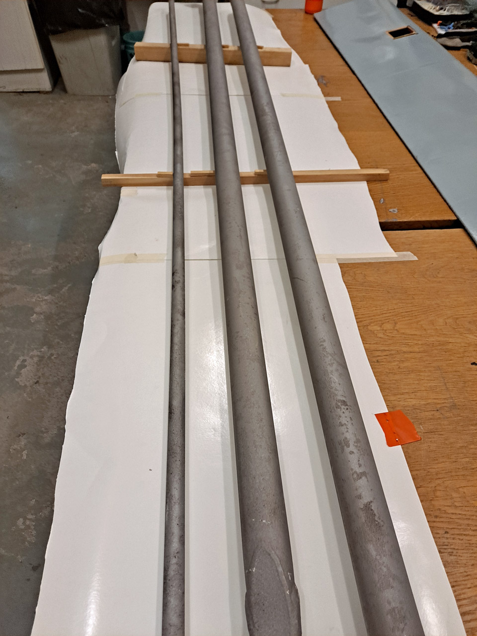
To make the missing rear strut, a 2,5 m long 22 mm thick steel tube was bought from Starkki hardware store. As a model for the building, a wing rear strut has survived. At both ends of the rear strut there’s a fixed bracket plate, with holes in it to fasten the strut to a bracket in the wing and the fuselage.
When we examined the photographs of Ressu at our disposal, we noticed that the lower end of the rear strut had been adjustable and not fixed, as was the case with the rear strut at our disposal. At the lower end of the strut can be seen a fork-like bracket with a threaded spindle. It was evident that the lower end of the rear strut had been changed to a fixed bracket. We decided to make the missing rear strut lower end adjustable, to correspond to the wing strut in the photograph. For this purpose we received a wing strut adjustable head used in a Super Cub.
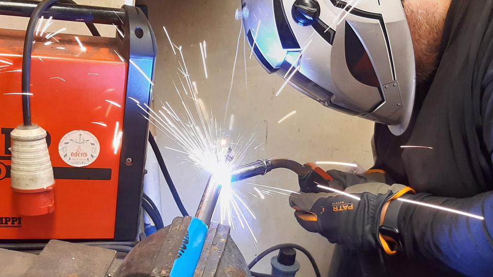
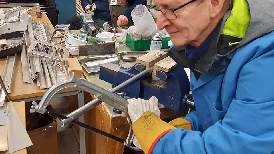
The building of the missing wing rear strut was started by cutting the steel tube to the measure of the rear strut. First we made the lower end of the rear strut. We welded a suitable nut, which fitted the threaded spindle of the lower end of the tube and screwed the bracket in place.
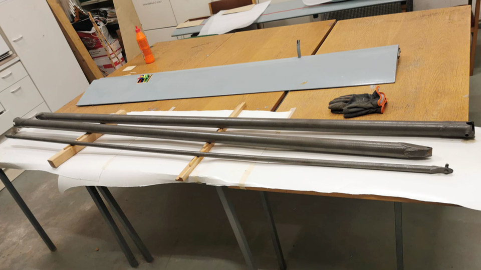
We made the wing rear strut top end a fixed one, according to the strut we had at our disposal. The end of the tube was sawn at an acute angle. After that the bracket halves for both sides were cut out of 2 mm metal plate to be welded in place. They were welded to the top sides of the tube. After welding, the bracket was ground to its final shape. When a hole had been drilled for the strut fastening bolt, the new strut was structurally finished.
The new wing strut was primed with light grey Isotrol paint, the same way as the three original ones had earlier been dealt with. After the primer had dried it received a coat of yellow Isotrol paint. Thus we had restored the two original front wing struts and a rear strut of the Ressu-aircraft and built the missing wing rear strut Photos by Lassi Karivalo. Translation by Matti Liuskallio. |
|
Avainsanat: aviation history, restoration, Tuesday Club, Hietanen HEA-23b, OH-XEA, "Ressu" |
The plywood covering of OH-XEA Ressu is under repairPerjantai 1.12.2023 - Tuesday Club member Ressu’s restoration has progressed well in the Finnish Aviation Museum’s restoration workshop. The left wing, ailerons, vertical stabilizer, rudder, horizontal stabilizer, wing struts and tail wheel assembly are all now under work. Maybe we should actually be talking about repairs, because Ressu is mainly in good condition – except the fuselage and vertical stabilizer. Therefore we mainly concentrate on repairing the damages in the plywood covering.
The aim in repairing the damages in Ressu’s plywood covering is to save as much of the original plywood as possible. Where a blow has damaged the covering and the plywood is still a strip which is in one piece, we aim to repair the damage by gluing the strip back into place, using a supporting piece of new plywood. However, if the damage is an open hole, the plywood is shattered, or there is a piece of plywood missing, we will patch the damaged area with new plywood. The latter repairing method is introduced in this blog, using the repair of the damaged plywood covering on the elevator as an example. In all cases the glued seams of the patches are spackled and sanded, and the patched area is painted to the original hue of the painted surface so that the damaged area can hardly be noticed.
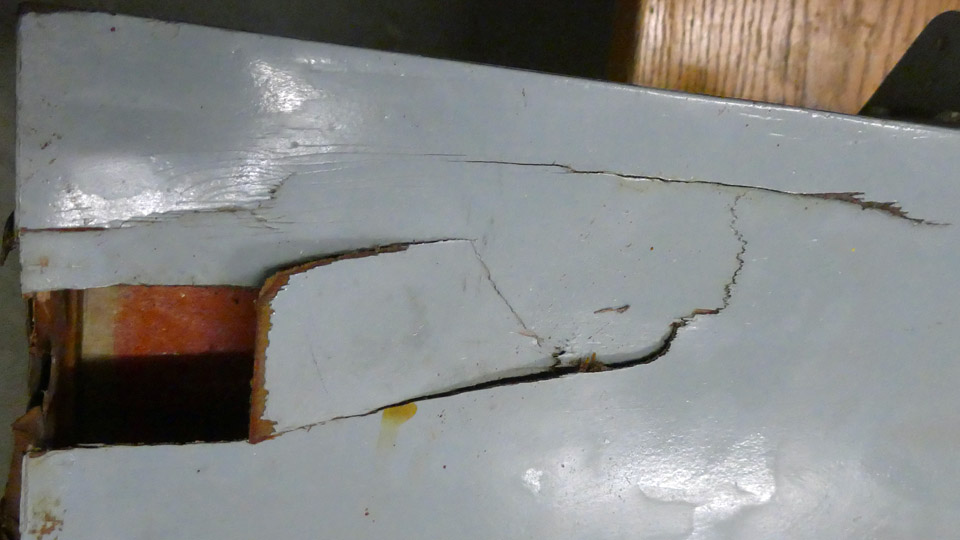
The plywood covering of Ressu’s elevator had one larger damaged area to be repaired. The damaged area is located on the elevator’s left-hand end, in the trailing edge side corner. Here the plywood covering has been broken on the elevator’s upper side and on its end. The plywood has broken in several places and parts of the covering are missing. We decided to patch the whole damaged area with new plywood.
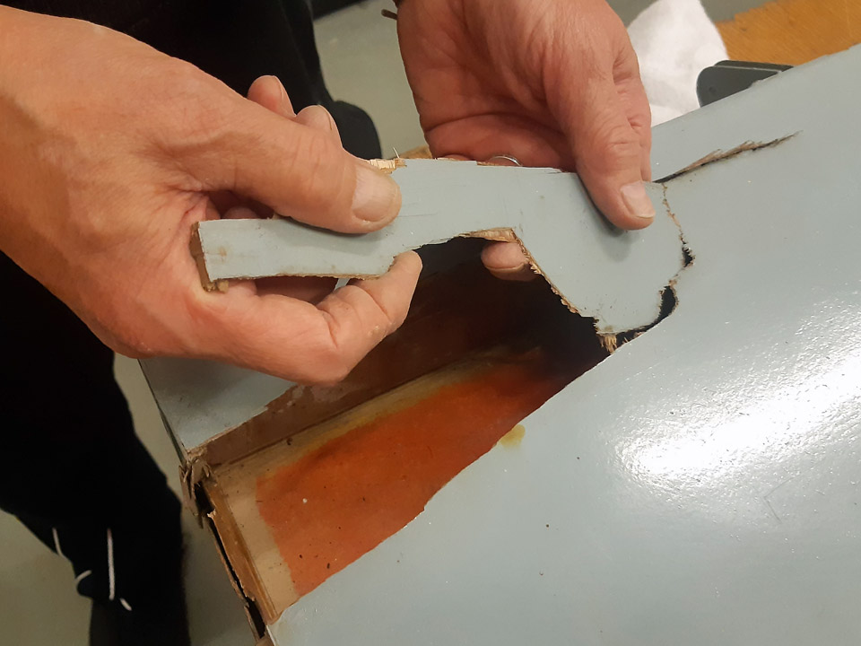
First we removed the broken pieces of the covering plywood at the damaged point on the upper surface. Then we drew a rectangle around the damaged area and cut the plywood off along its edges, using a Dremel circular saw blade. This is how we created an opening for the patch on the upper surface. In a similar manner we cut a rectangular opening around the damaged area on the elevator’s end. Now the whole damaged area had been opened for patching.
The next step was to fasten supporting strips on the edges of the opening. The plywood patch will be supported by these strips when it is glued to cover the opening. Some of the supporting strips were glued with strengthening nails to the structure of the elevator. A strip was fastened also on the area where the patches on the elevators upper surface and on its end meet, i.e. at the upper edge of the elevator’s end.
Photo by Antti Hietala. One of the supporting strips was glued on the underside of the plywood edge so that a little less than one centimetre of the strip was left outside the plywood covering’s edge. Before gluing, the old varnish was sanded away from the underside area of the plywood covering which was to be glued. The supporting strip was glued on the edge of the plywood covering and pressed tight on the plywood with small plastic clamps. The glue we used was Casco Outdoor wood glue. Furthermore, a longitudinal supporting strip was fastened across the opening on the upper side. This strip is needed to support the plywood patch on the opening and make it slightly curved so that it follows the gently curving profile of the elevator’s upper surface.
When the supporting strips had been fastened, patch pieces of 1 mm aircraft plywood were cut for the openings on the upper side and the elevator’s end. The patches were fitted into place, shaping their edges until the patch edges pressed tightly against the sides of the opening.
Photo by Matti Kainulainen. First the plywood patch was glued into place on the elevator’s end. The upper edge of the patch was pressed against the supporting strip with small clamps and the glued seam on the lower edge was secured with some small nails.
Photo by Matti Kainulainen. Then the larger patch on the upper surface was glued into place. On the elevator’s leading edge side, the glue seam of the plywood patch could be pressed tight with ordinary clamps. A piece of plywood was placed between the clamps and the glue seam to distribute the pressure evenly on the seam. On the other side of the opening a metal weight was placed on the glued seam to press the plywood patch against the supporting strip.
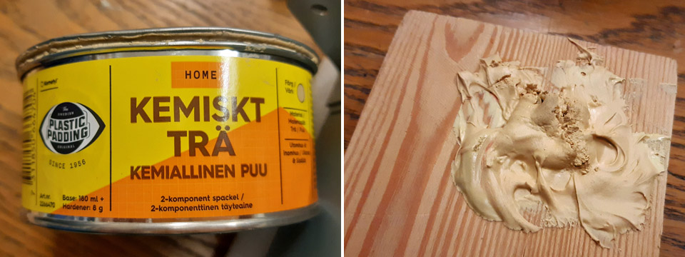
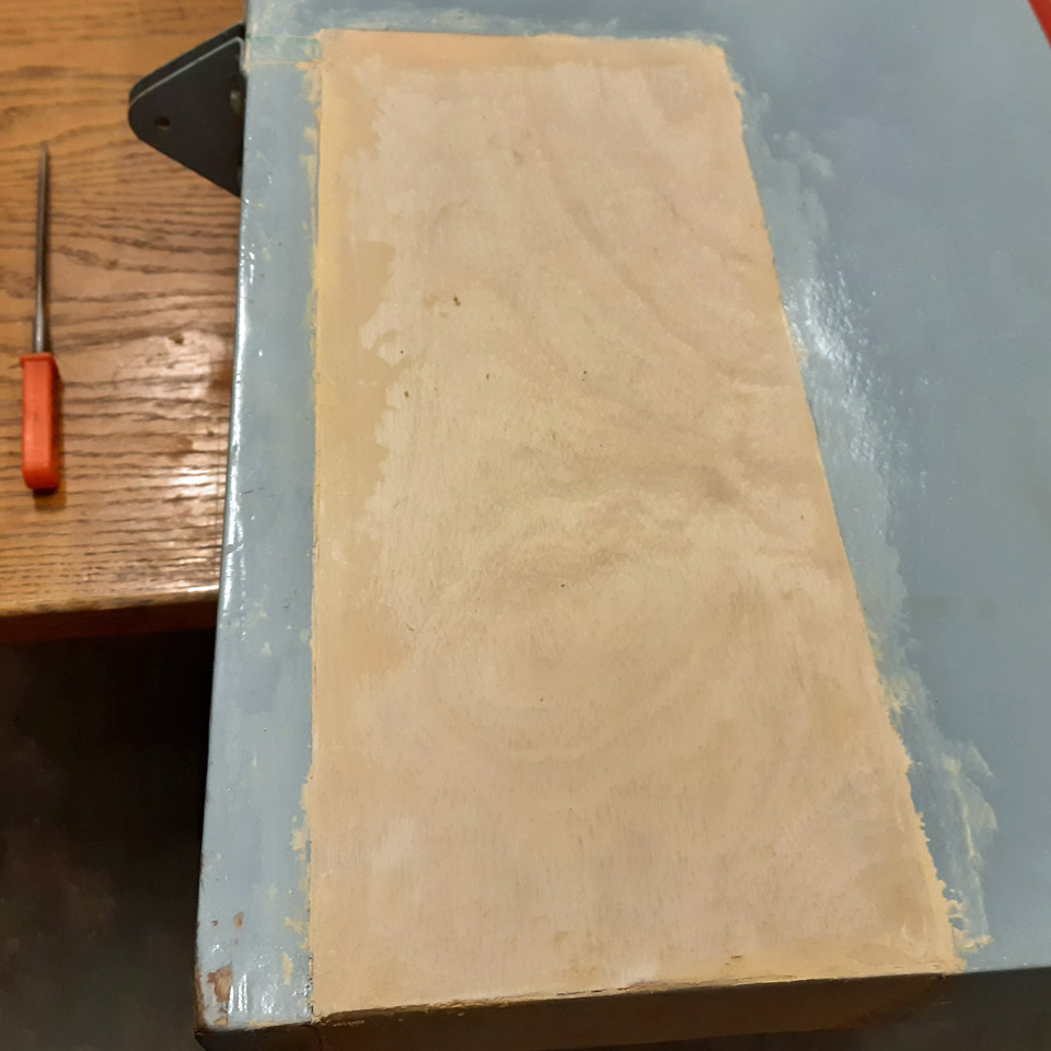
The gluing of both plywood patches went well. The patch seams were spackled using Plastic Padding’s two-component Chemical Wood. The spackled seams and the whole newly patched area will be sanded before painting. The plywood patches will be painted later, together with several other plywood patches on Ressu’s surfaces. Photos by Lassi Karivalo except if otherwise separately mentioned. Translation by Erja Reinikainen. |
|
Avainsanat: aviation history, restoration, Tuesday Club, Hietanen HEA-23b, OH-XEA, "Ressu" |
The restoration of OH-XEA Ressu has been startedTiistai 21.11.2023 - Tuesday Club member As told in the previous blog, the parts of the OH-XEA, designed and built in the 1960s by the Hietanen brothers from Turku, will be restored by the Tuesday Club. The aircraft was nicknamed Ressu. Its wings, horizontal stabilizer, elevator, rudder, tail wheel assembly, wing struts and fuel tank have been brought to the Finnish Aviation Museum. We will concentrate on the restoration of its fuselage frame later. When the condition assessment and the restoration plan of the Ressu’s parts brought to the Museum had been completed, it was time to set to work.
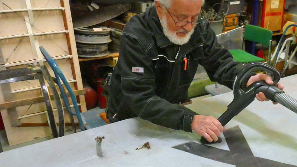
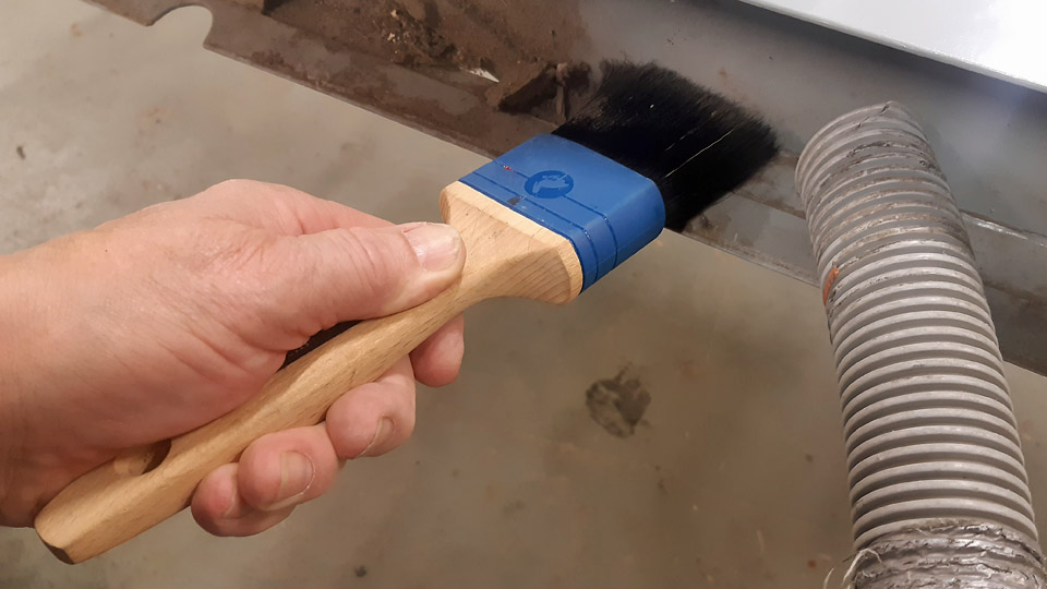
The restoration of the wings was started by cleaning the plywood surfaces, painted blue. Both wings were brought to the restoration workshop of the Finnish Aviation Museum. We started the cleaning of the painted wing surfaces with a well-tried method: a magic sponge. Naturally the worst dust was first vacuumed off. The aileron was unfastened to be washed separately. The dust in the joint of the aileron and the wing was brushed off with a paint brush and vacuumed clean.
When using a magic sponge no cleaning agent is used. The tools you need are the magic sponge, a soft cloth, and half a bucket of water. The painted surface of the wing is cleaned by rubbing the surface of the wing, a small area at a time, with the magic sponge dipped in water and squeezed damp. With the soft cloth in the other hand the rubbed area is wiped at short intervals. The magic sponge removes the dirt from the wing surface, and it is wiped off with the cloth, which is rinsed in the bucket. There were also splashes of red paint on Ressu’s wings. Even they could be removed with the magic sponge. The rubbing with the magic sponge does not damage the painted surface unless excessive force is used.
The plywood covered horizontal stabilizer and elevator were treated in a similar manner. We managed to get their surfaces very clean too. We were satisfied to see that after the wash the greyish blue surfaces of the wings, horizontal stabilizer and elevator were as if newly painted. We wonder whether they have been painted in the 1960s using durable Miranol enamel paint as the painted surface has been so well preserved.
For the rudder surfaces no washing was needed, but the covering fabric was removed from the metal frame of the rudder. The covering fabric needs to be completely replaced. A carpet knife was used when removing the fabric. We could see that a strip of fabric had been spun around the outer edges of the frame. This strip protects the fabric which covers the metal rudder frame. On the other hand the covering fabric can be sewn on the fabric strip, but we could not tell whether this had been the case here. The fabric strip covering the edges of the metal frame was removed with a carpet knife. The rudder’s metal frame, stripped of the covering fabric, is now ready for rust removal and the surface treatment after it.
Photos by Reino Aatsalo.
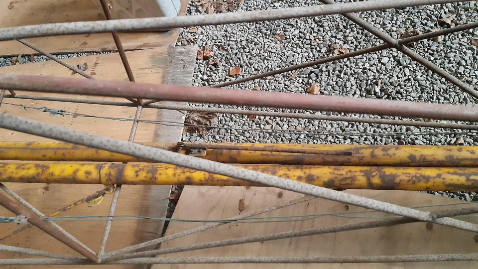
Photo by Antti Hietala. Three of the Ressu’s four wing struts have been preserved. The struts are surprisingly heavy, so they are probably made of ordinary steel tube. The surfaces of the struts have been painted yellow but are now covered in rust. The surfaces were sandblasted clean. Then the struts were treated with Isotrol varnish which prevents rust. Now the wing struts are waiting for their final surface treatment, and they will be painted yellow as in the original paint scheme.
Photo by Lassi Karivalo.
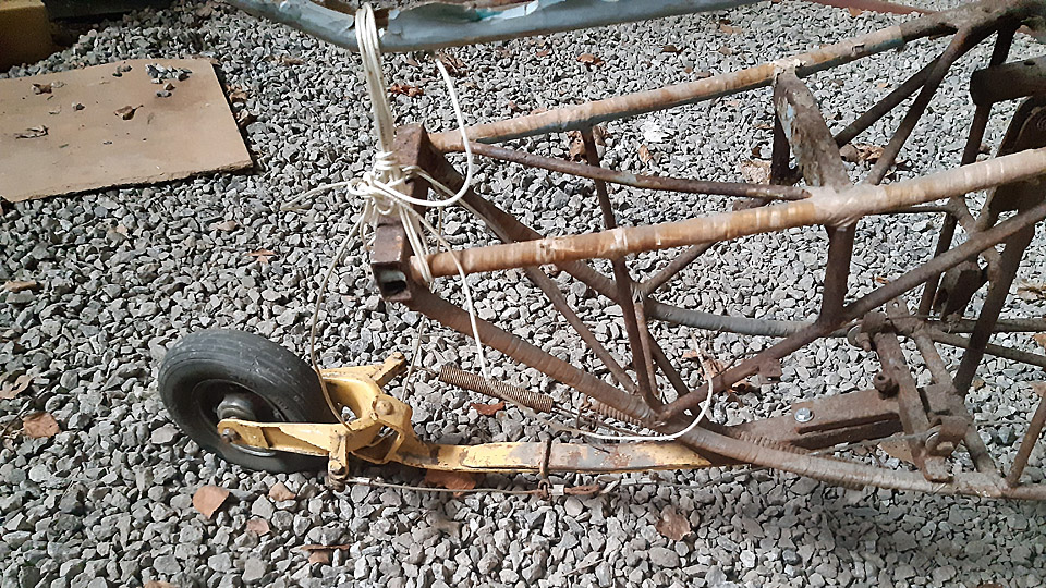
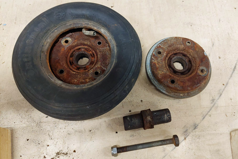
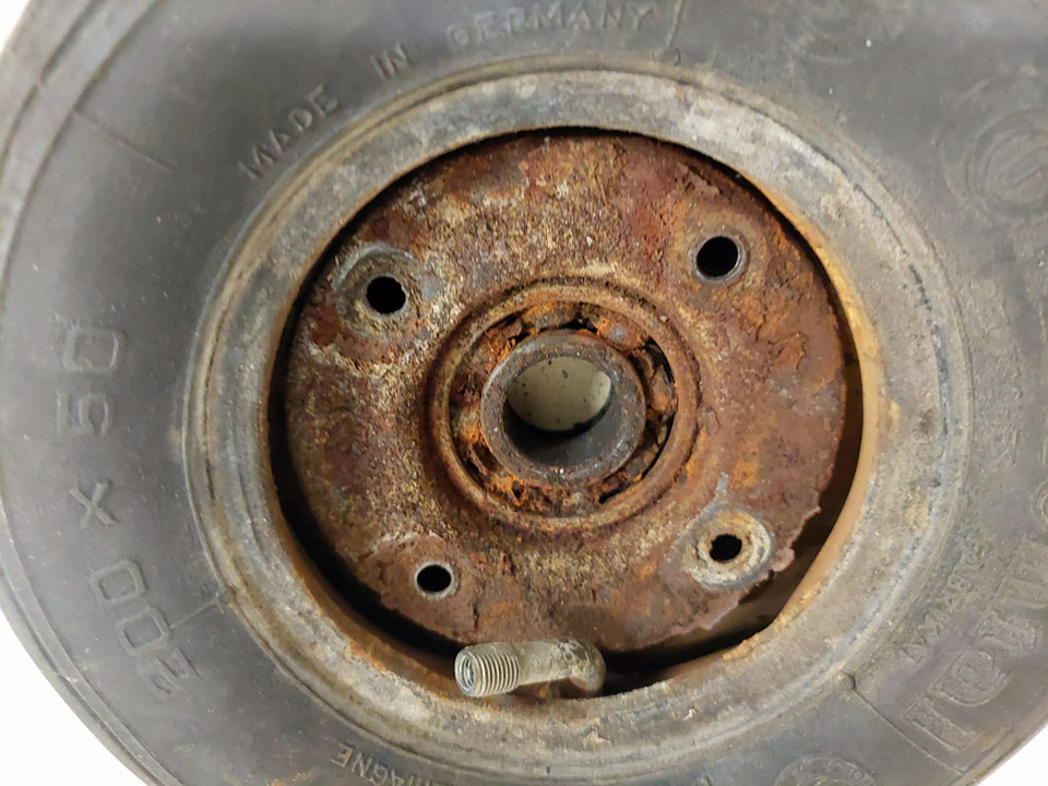
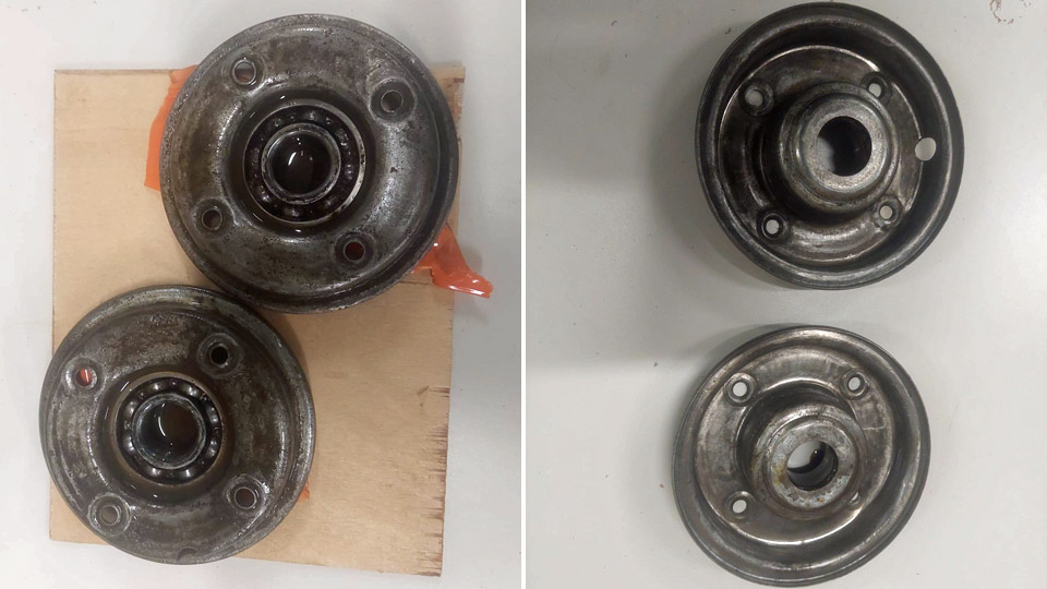
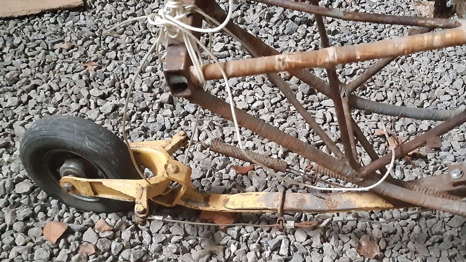
Photos by Osmo Väisänen. The restoration of Ressu’s sprung tail wheel assembly was started by disassembling it. Even the tail wheel had to be disassembled so that we will have access to the wheel bearings, which are totally jammed. When the four bolts on the wheel rim had been unfastened, the rusty wheel halves could be wrenched apart by force. When the bearings were visible, we sprayed a lot of rust removing chemical in them and on the rusted surfaces of the wheel rim and left them “to mature” for a week. When a week had passed, we were able to clean the wheel rim halves quite well from rust and the bearings were preliminarily working. The following task will be to repair the sprung tail assembly. Photos by Lassi Karivalo except if otherwise mentioned. Translation by Erja Reinikainen. |
|
Avainsanat: aviation history, restoration, Tuesday Club, Hietanen HEA-23b, OH-XEA, "Ressu" |
The condition and damage assessment of Hietanen OH-XEA Ressu and its restoration planSunnuntai 19.11.2023 - Tuesday Club member The Tuesday Club is starting the restoration of the Hietanen OH-XEA Ressu aircraft which has been stored at Lemu in the Turku area. The aircraft was built in the 1960s by Ari and Esko Hietanen from Turku. The first phase of the restoration will include the wings, horizontal stabilizer, elevator, rudder, tail wheel assembly, wing struts and fuel tank, which have been brought to the Finnish Aviation Museum from Lemu. The fuselage has no covering, but it remained at Lemu, and its turn will come later. The first step in the renovation work is to assess the condition of the aircraft and its possible damage. Therefore we took the Ressu’s parts into the restoration workshop at the Finnish Aviation Museum and went carefully through the condition and damages of each part and made preliminary restoration plans for them.
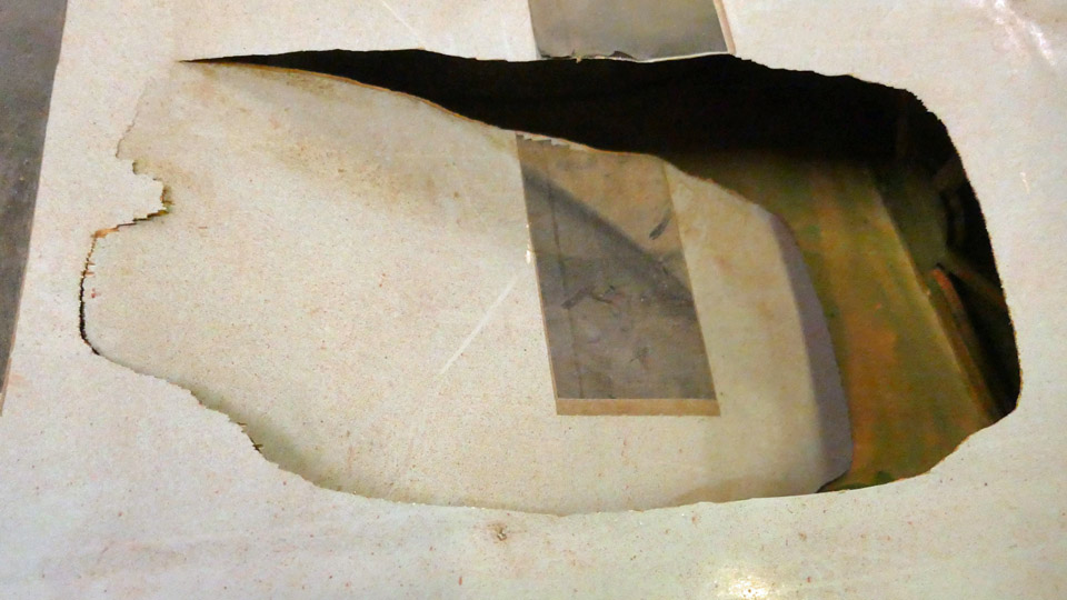
We could see that the plywood covered surfaces of the wings, horizontal stabilizer and elevator are very dirty and have stains of red paint. The damages on the plywood covering are mainly small crushes or holes. However, on the underside of the left wing there is a large area around the registration mark where the plywood covering is badly broken. Or should we say has been intentionally broken – it certainly looks that way. The first phase in the restoration will be to clean the surfaces of the wings, horizontal stabilizer, and elevator and then to repair the damages on the plywood covering.
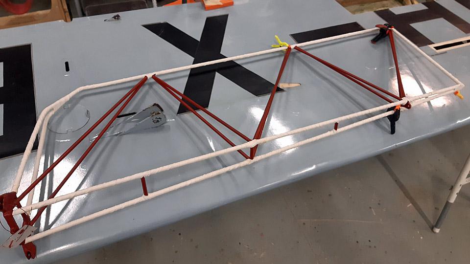
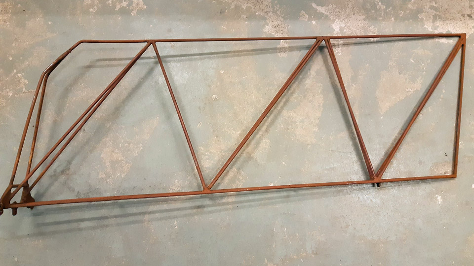
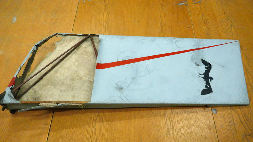
Ressu's rudder has metal structure and fabric covering, in similar manner as the tubular structure fuselage. The covering fabric is torn on one side of the rudder and a piece is missing.
The rusty metal frame of the rudder can be seen under the torn fabric. The metal frame will be cleaned and painted as it originally was. It seems that the frame has been painted with red Ferrex, the anti-rust paint which was commonly used in the 1960s. The red colour is visible under the rust. We will paint the frame using modern red Isotrol paint.
Finally the rudder will be covered with new fabric and painted pale blue, following the original paint scheme. Red stripes will be painted on both sides of the rudder, following the original look. Number 2 will be painted on the left side and a black bird figure on the right.
Ressu's tail assembly has metal structure and an air-filled tyre. The wheel bearings are completely stuck. We will try to repair the wheel into operating condition. The tail frame will be cleaned of rust and painted yellow, following the original paint scheme.
Ressu’s wings are supported with two wing struts, made of metal tube. Two of them are sturdier, fastened on the brackets on the wing’s front spar, and the two thinner ones are fastened on the brackets on the rear spar. We have both front struts but only one rear strut. The wing struts had been stored inside Ressu’s fuselage frame. The struts have been painted yellow but are now badly covered in rust. They will be sandblasted clean by a contractor and painted yellow as the original ones. We will make a new rear strut to replace the missing one.
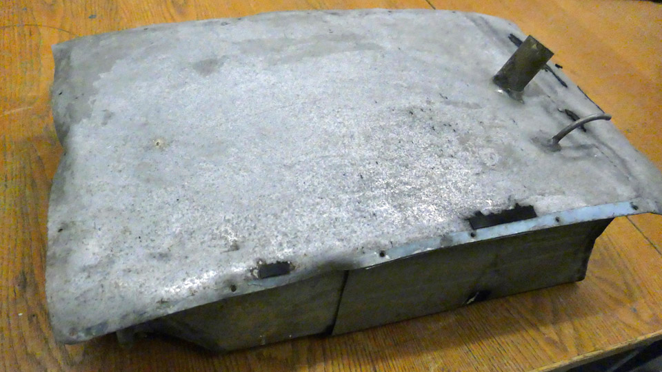
The fuel tank is located at the root of the left wing, it has been lowered into place from the upper side of the wing. The fuel tank has dents, and they will be straightened. The fuel tank has had some kind of cap with a rubber seal, there are marks of it left on the wing as well as on the tank. The cap has disappeared. If we can find out what the cap has been like, we will make one. And if we can’t find what it has been like, a good alternative is to make a cap from e.g. 1,2 mm thick aircraft plywood. The Hietanen brothers have obviously been planning to double the size of the 21-litre fuel tank. We can judge this from the fact that the wing rib next to the tank had already been removed and the wing’s plywood covering had been opened between the wing spars up to the following rib. We will, however, restore the wing structure to its original condition where there is only space between the wing root rib and the first rib for the original fuel tank. This means that the missing rib will have to be made and the opened plywood covering repaired. Photos by Lassi Karivalo. Translation by Erja Reinikainen. |
|
Avainsanat: aviation history, restoration, Tuesday Club, Hietanen HEA-23b, OH-XEA, "Ressu" |
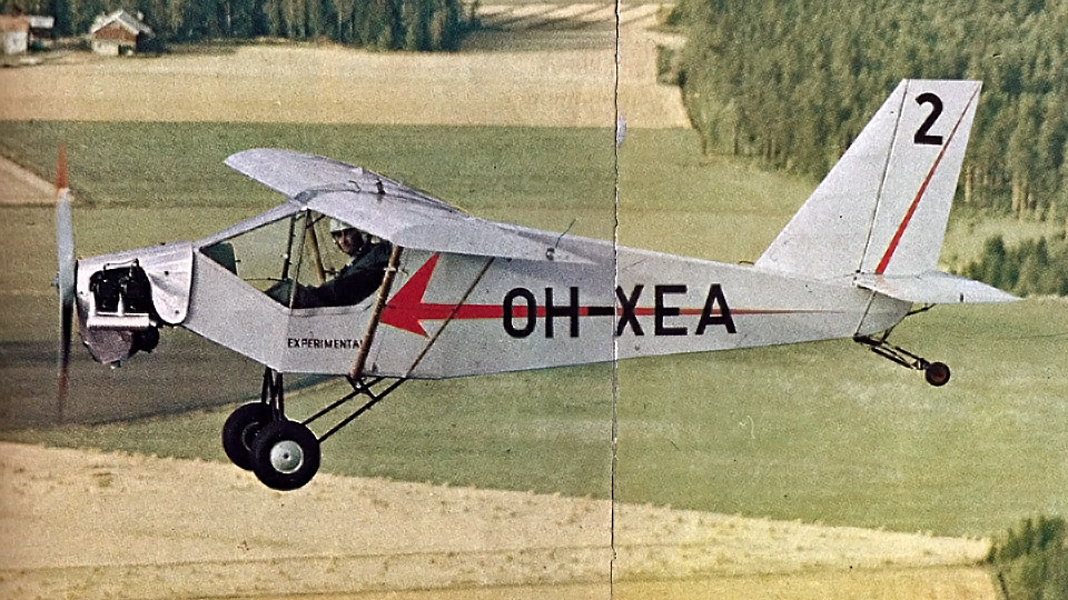
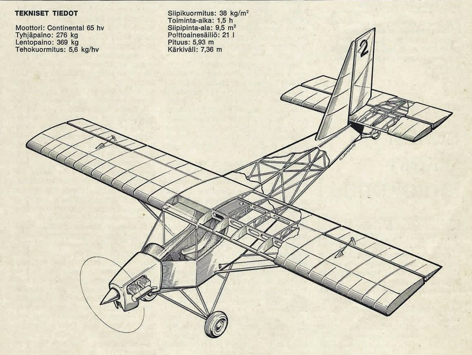
Hietanen OH-XEA "Ressu" to be restored by the Tuesday ClubPerjantai 10.11.2023 - Tuesday Club member Last year Aviation Museum Society Finland was donated a single-seat experimental aircraft, designed and built in the 1960s by Esko and Ari Hietanen, two brothers from Turku. The aircraft was inspected and registered in the civil aircraft register on August 13th, 1969, with the registration OH-XEA. The aircraft, nicknamed Ressu (meaning Snoopy), is a high-winged, mixed structure single-seat aircraft. The tubular framed fuselage is fabric-covered. The wings, ailerons, vertical stabilizer and rudder have wooden structure and plywood covering. The rudder is tube-structured and fabric-covered.
Photo via Aviation Museum Society, Finland. Ressu is a small aircraft. Its wingspan is 7,4 m and the fuselage is 5,5 m long. The widest part in the fuselage is the landing gear, with 1,4 m from one end of the axle to the other. In its time, Ressu had several registration marks. First it was registered as H-EA (Hietanen Esko and Ari), then OH-HEA and eventually OH-XEA when it was approved in the civil aircraft register. Ressu’s engine was Continental A 65. The aircraft was removed from the civil aircraft register on January 1st, 1973. We don’t know how many hours Ressu has flown.
Photo via Aviation Museum Society, Finland. After the flying activity ended, Ressu was stored in several places and its fuselage was badly damaged. Today the fuselage has no traces of the fabric covering and the tubular frame is covered in heavy rust. In the cockpit there is just the pilot’s seat, control stick, pedals, and an empty instrument board. The engine, the instruments from the cockpit panel and the landing gear wheels have all disappeared during the years. Out of four wing struts only three remain. The wings were painted pale blue, the horizontal stabilizer and the elevator have been preserved quite well, there are only some damages on the plywood covering. The fabric covering of the rudder is broken and the paint on the fabric is badly crackled. The fabric covering on the fuselage has probably been painted pale blue as the wings.
The aim is to restore Ressu at the Tuesday Club to resemble its appearance in 1969 when it was registered. This means that the plywood covered surfaces of the wings and parts of the tail will have to be cleaned and the damages repaired. After that we can consider restoring the fuselage. There the first step would be to treat the rusty fuselage before covering it with fabric. We will try to find instruments for the cockpit if we are able to find the kind of instruments Ressu had. The engine could well be a discarded and inoperative Continental A 65, if we could find one.
Photo by Elias Viitanen.
In autumn 2022 Aviation Museum Society Finland volunteers assembled Ressu in the former shipyard hall in Pansio where the Caravelle III, owned by the Society, was under restoration. Ressu was also on display at the Society’s stand in the Turku Airshow in June.
After that Ressu has been stored at Lemu, in the Turku area. From there we fetched Ressu’s wings, horizontal stabilizer, elevator, rudder, tail wheel assembly, fuel tank and wing struts, and brought them on a trailer to the Finnish Aviation Museum in Vantaa. In the Museum’s restoration workshop the Tuesday Club members have already started the restoration of Ressu’s parts. The fuselage remained at Lemu, but it will probably be taken under restoration next year. The Tuesday Club has now started Ressu’s restoration project which is estimated to take a couple of years. Photos by Lassi Karivalo except if otherwise mentioned. Translation by Erja Reinikainen. |
|
Avainsanat: aviation history, restoration, Tuesday Club, Hietanen HEA-23b, OH-XEA, "Ressu" |
Ilmailumuseot.fi - Aviationmuseums.fi