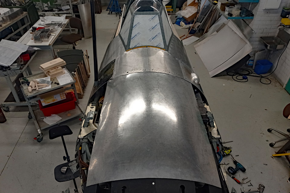
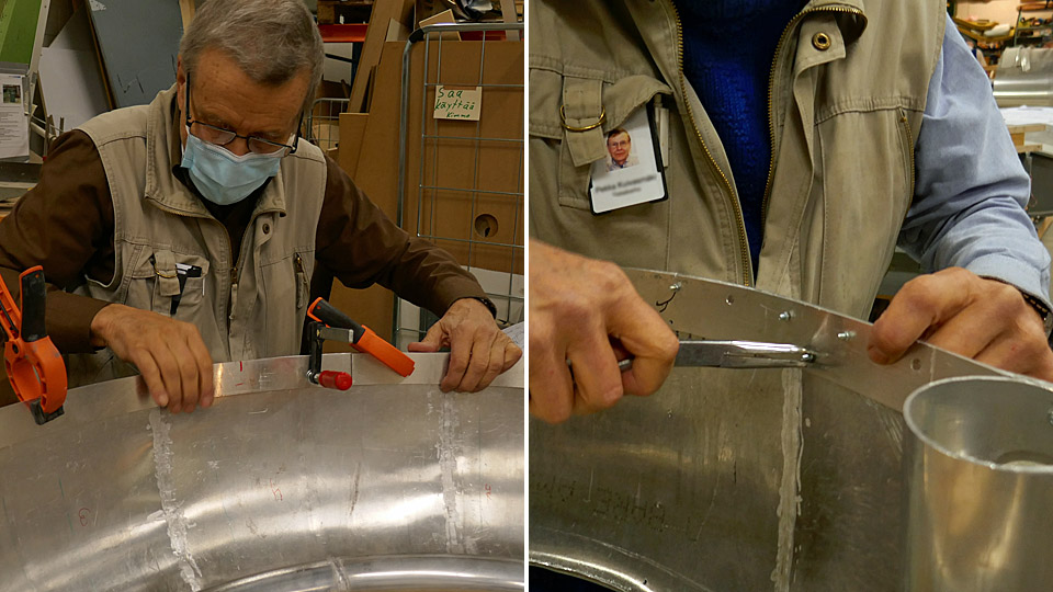
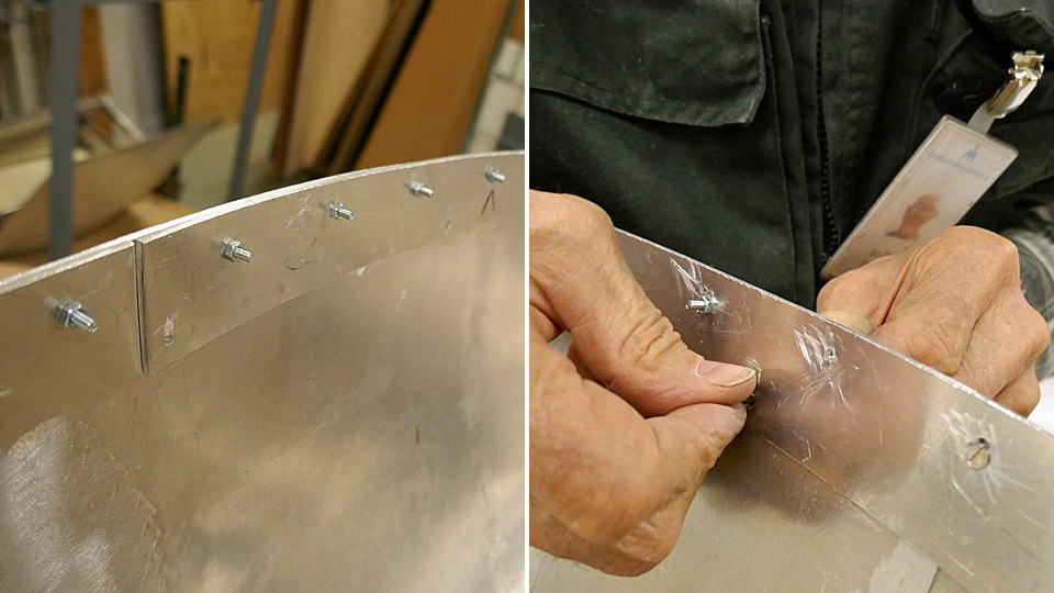
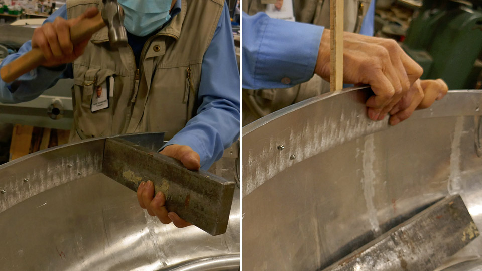
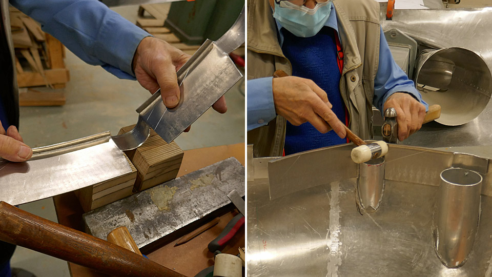
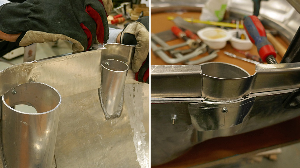
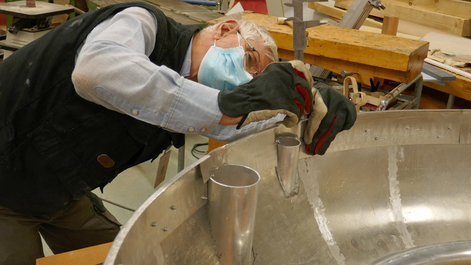
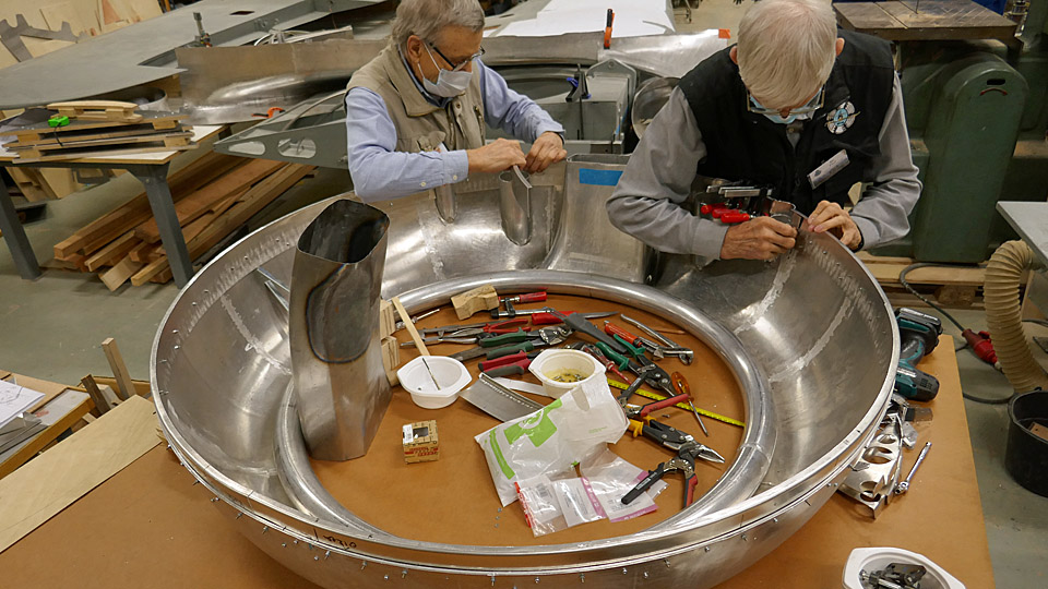
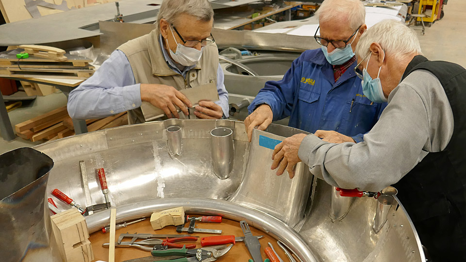
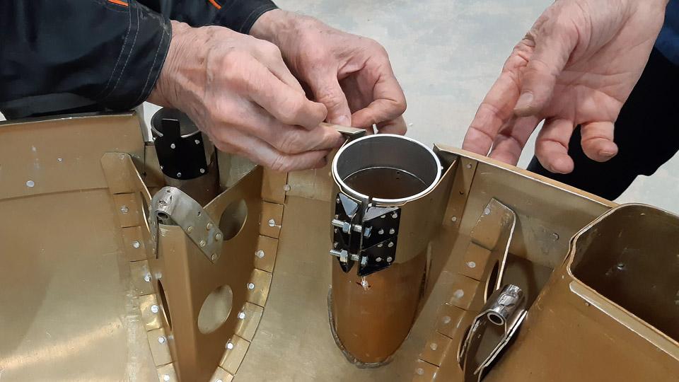
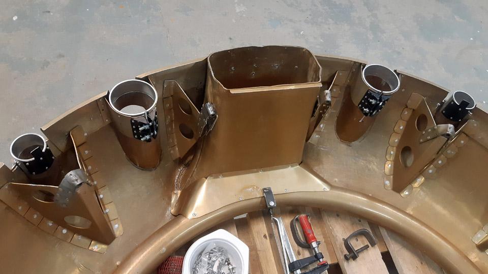
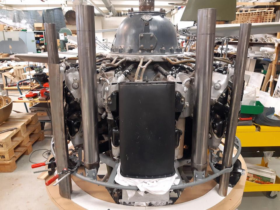
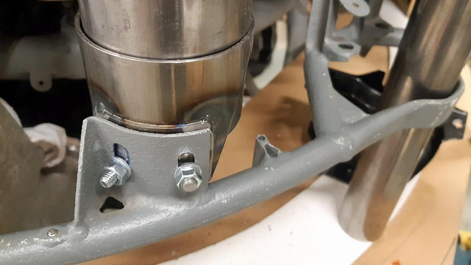
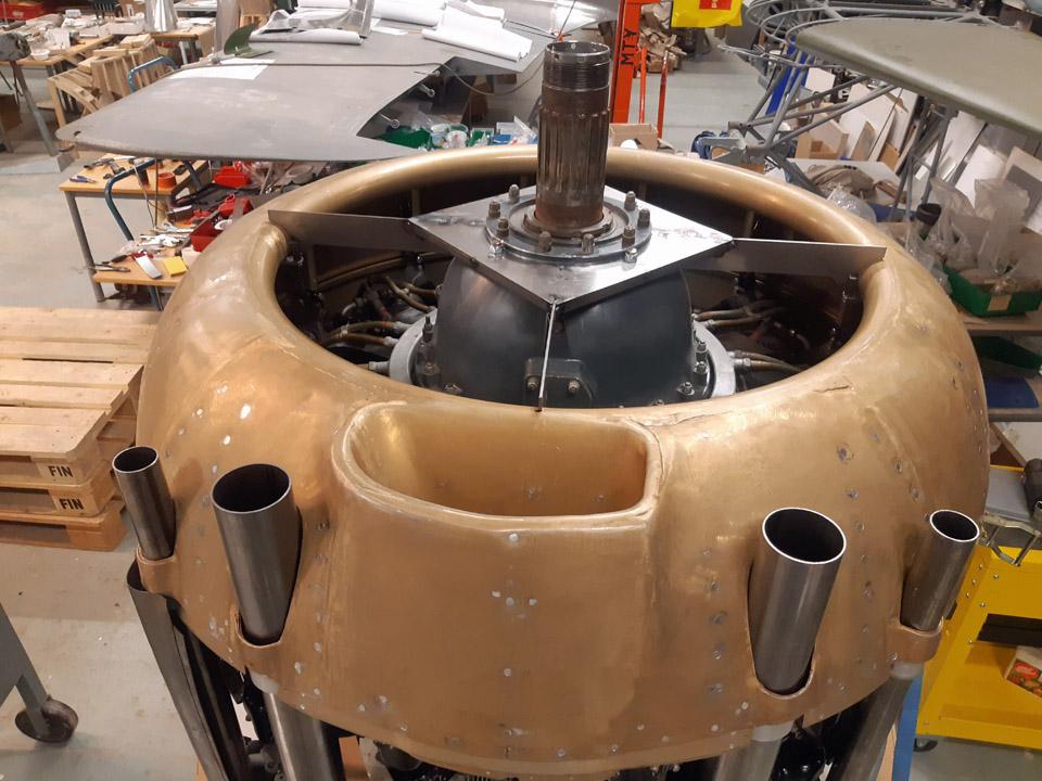
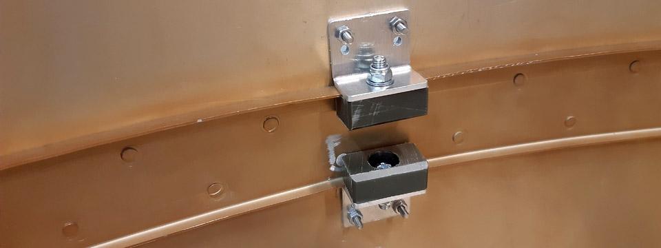
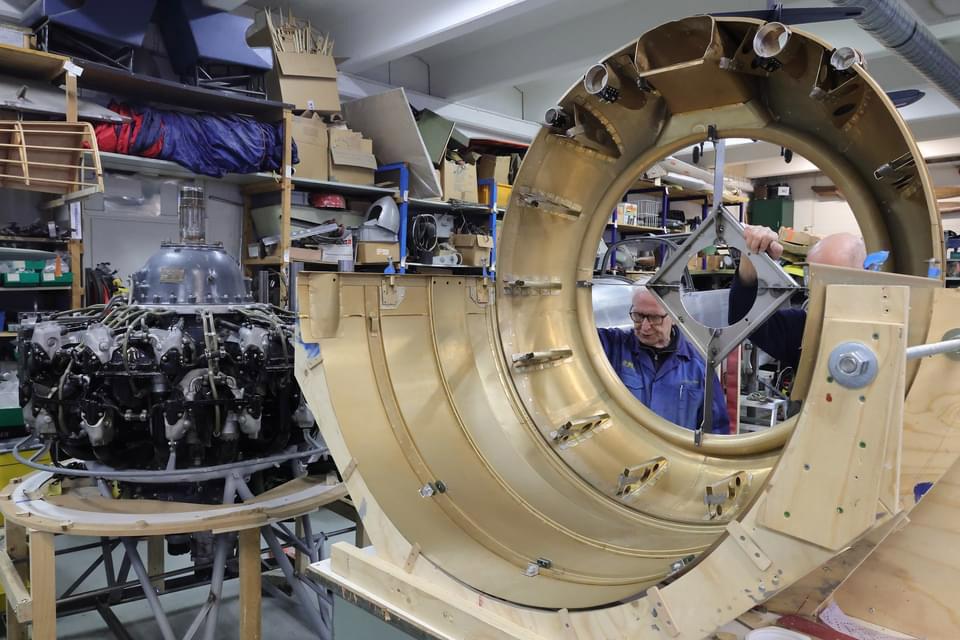
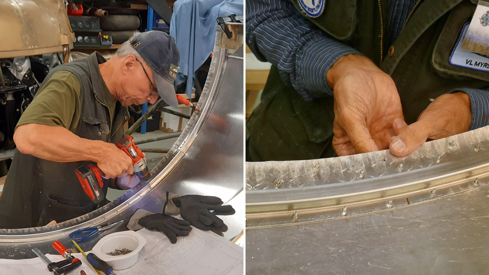
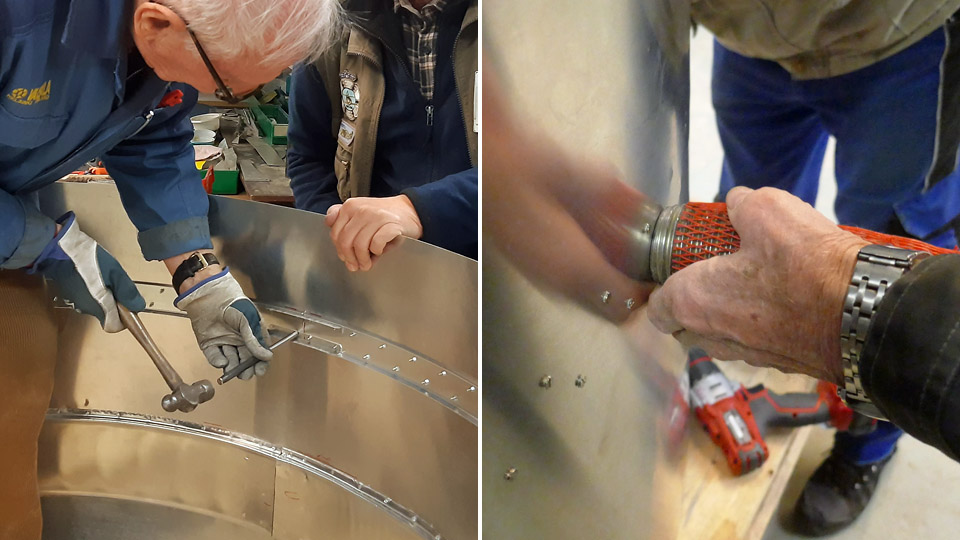
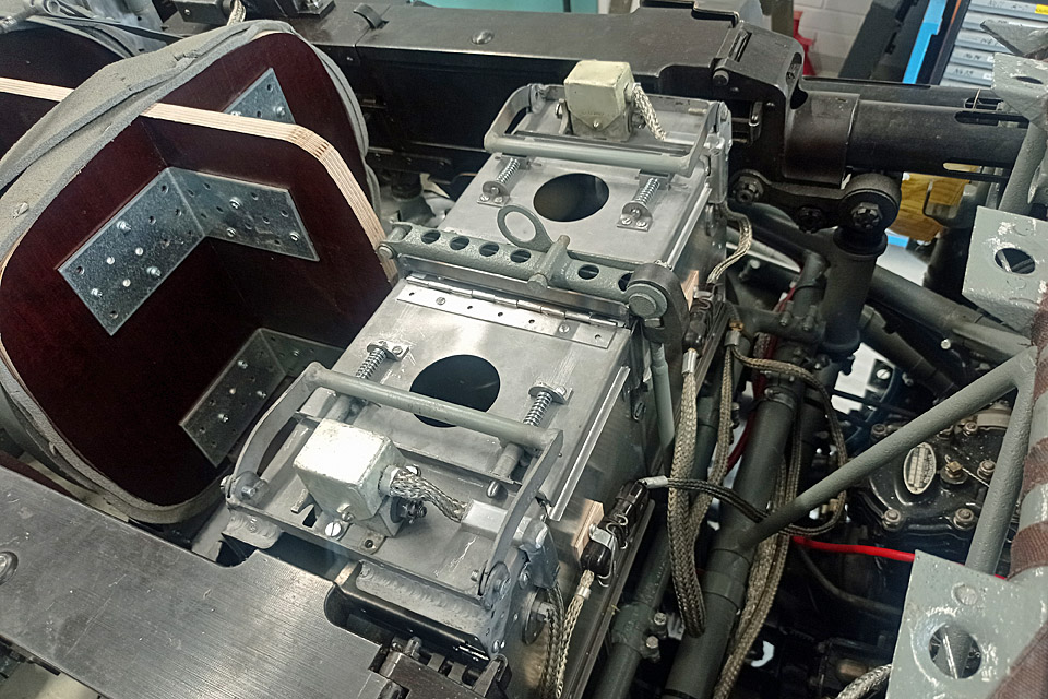
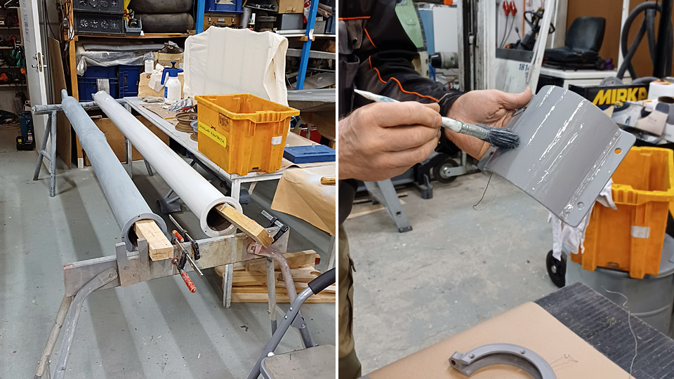
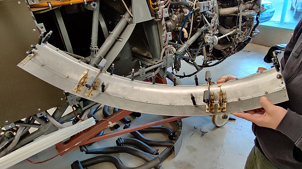
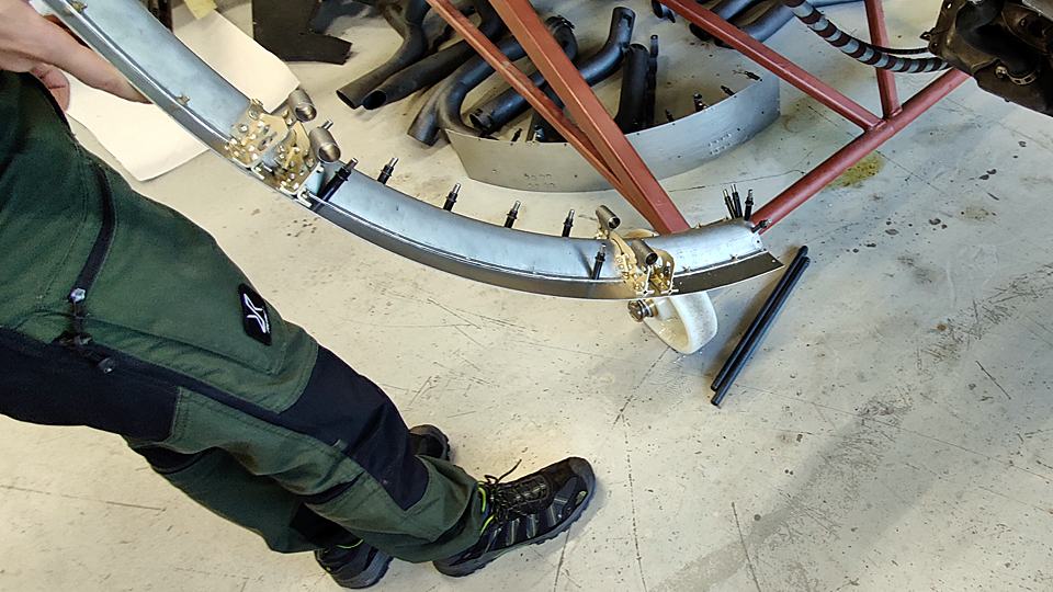
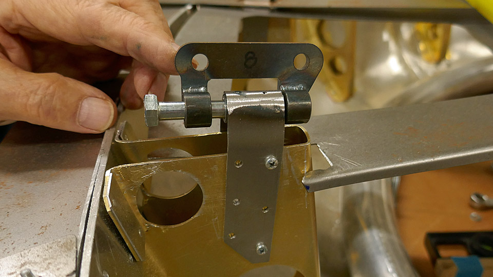
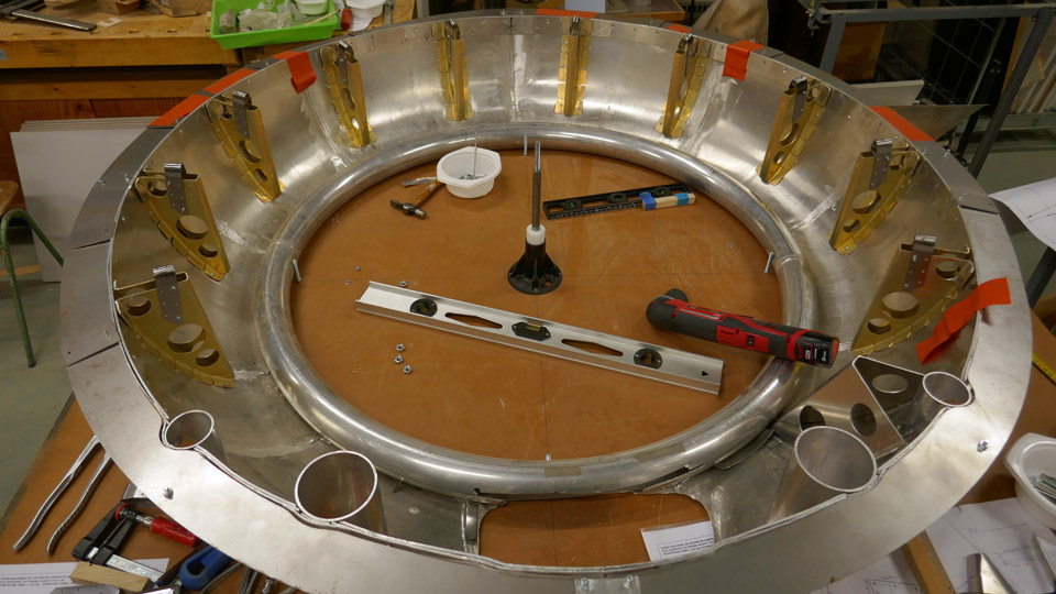
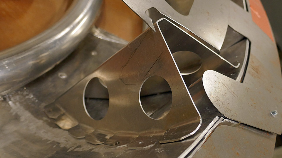
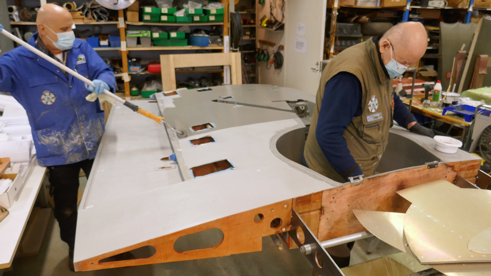
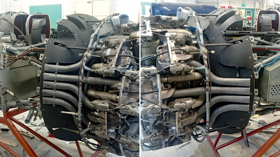
The Myrsky engine NACA-ring and lower cowling completionKeskiviikko 7.2.2024 - Tuesday Club member The engine’s NACA-ring of the VL Myrsky II (MY-14) under restoration was completed when the tightening collars, made at the Tuesday Club for the four machine gun flash tube openings at the upper part of the NACA-ring, were fitted. With the tightening collars the flash tubes made of steel will be locked to the four openings intended for them in the NACA-ring. Of the four openings the two midmost will have 70 mm flash tubes and the lateral ones will have 45 mm flash tubes. The midmost flash tubes will be fastened at their rear end to brackets on the ring of the engine cradle. The machine gun barrel will thrust itself into the rear end of the lateral flash tube, holding it in place.
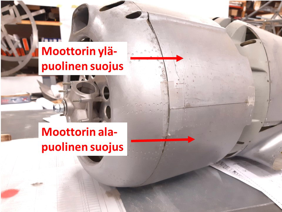
The excessively long flash tubes are still “sticking out” of the NACA-ring flash tube openings. They will be cut shorter, so that the flash tube ends will only protrude to some extent out of the flash tube openings. The difference in sizes of the flash tubes is due among other things to the fact that there’s no room at the side of the engine under the upper cowling for thick flash tubes. There are shields as well made of steel plate above these narrow flash tubes. They protect the upper cowling, which is nearly touching the flash tube, from overheating when the machine gun is firing. But all the same, both sizes of the flash tubes serve the four 12,7 mm LKk/42 machine guns.
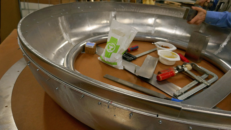
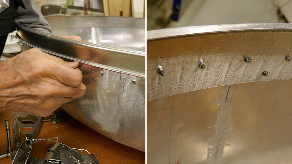
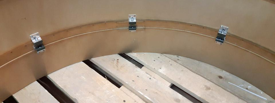
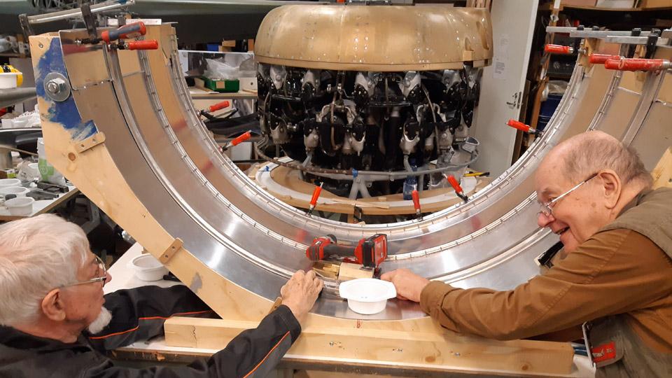
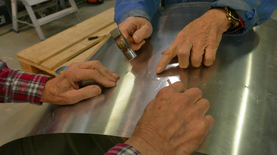
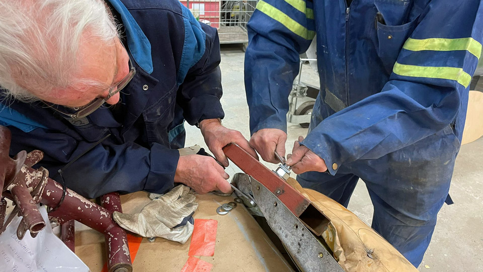
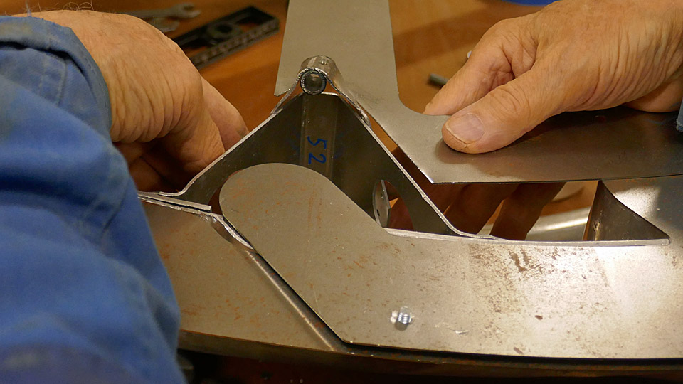
Building of the lower cowling is almost completed at the Tuesday Club. The last tasks have been the guides, which will be fastened on the cowling’s inside surface stiffening strip, the guiding pegs to the front end of the cowling, and the tightening latches, with which the lower cowling will be locked to the upper cowling. Let it be pointed out, that the MY-14 engine upper cowling will be built in the Finnish Air Force Museum.
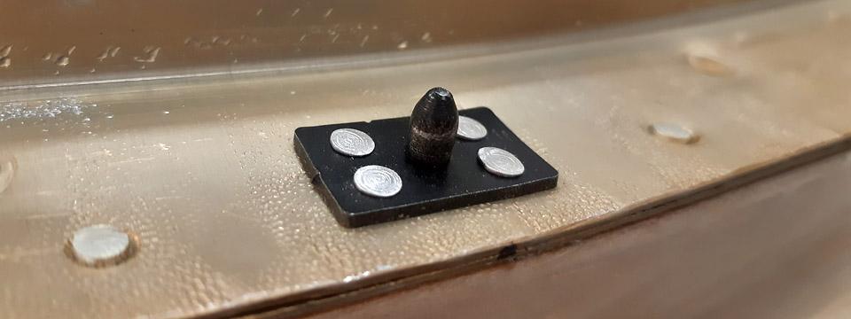
The guides, as well as the guiding pegs, and the tightening latches were made at the Tuesday Club. Owing to the guides and the guiding pegs, the lower cowling is easy to fit into place. Three slot-formed guides were riveted on the cowling’s inner surface rearmost stiffening strip. With the aid of these slot-formed guides the cowling “snaps” in place to the fastening ring of the rear part of the engine.
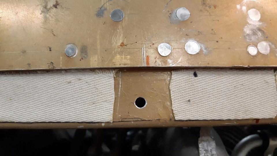
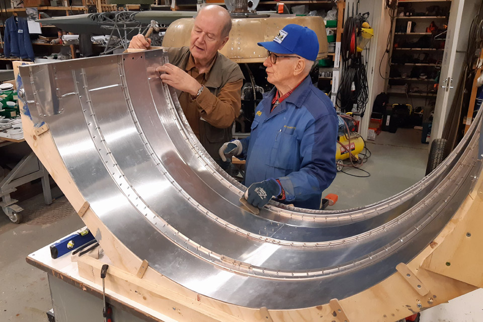
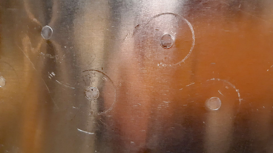
Photo by Jorma Laakkonen. The three guide pegs of the cowling’s front edge were riveted on the inner surface of the cowling’s front edge. The guide pegs of the front edge push into the holes drilled in the NACA-ring hem, thus fastening the cowling from its front edge on the NACA-ring. An insulation strip made of fabric was glued to the hem of the NACA-ring to separate the two metal surfaces from each other.
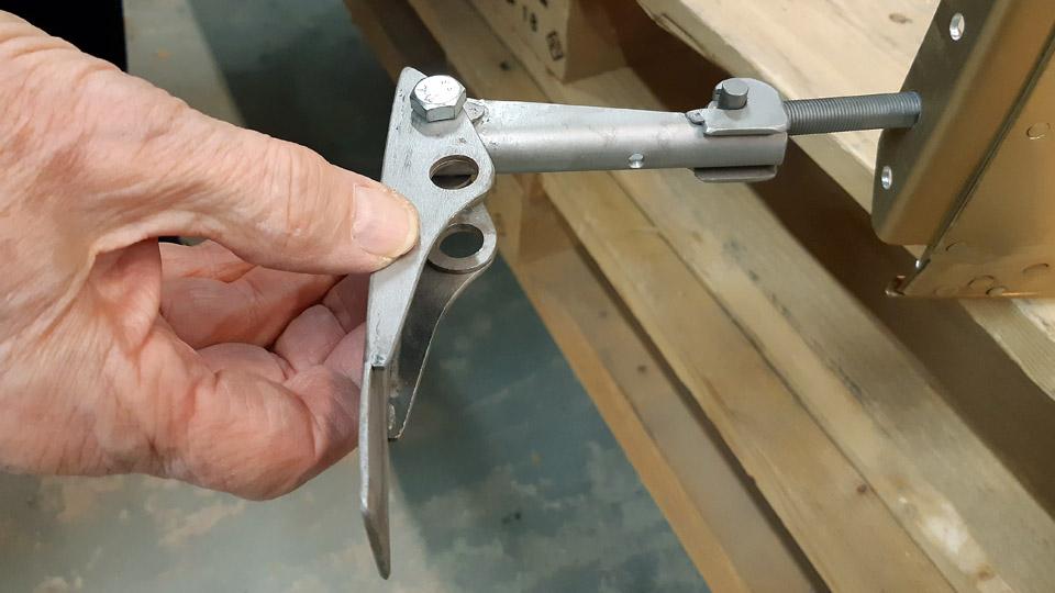
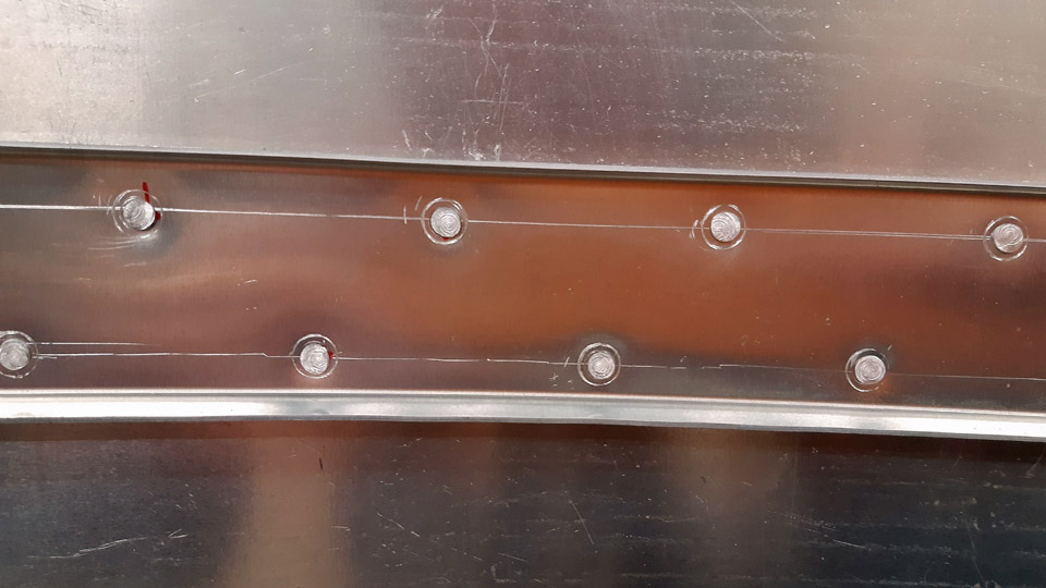
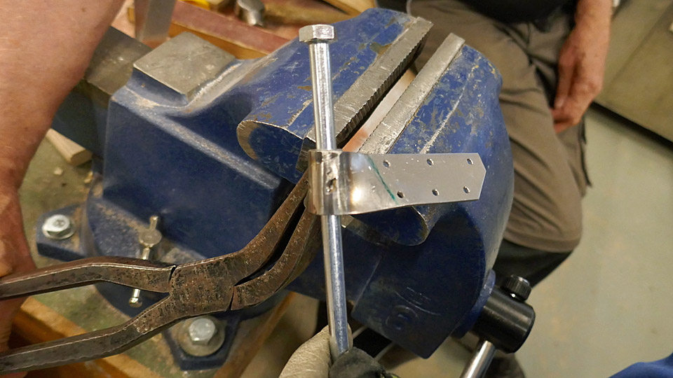
The upper and lower cowlings are locked to each other with four tightening latches. These four complicated tightening latches were built at the Tuesday Club, according to Myrsky blueprints. With adjustable tightening latches the upper and lower cowling can be locked to each other to suitable tightness. The parts of the latches with springs will be fastened to the upper edge of the lower cowling and the parts with levers to the upper cowling. The parts of the latches with springs are tentatively in place, waiting to be riveted.
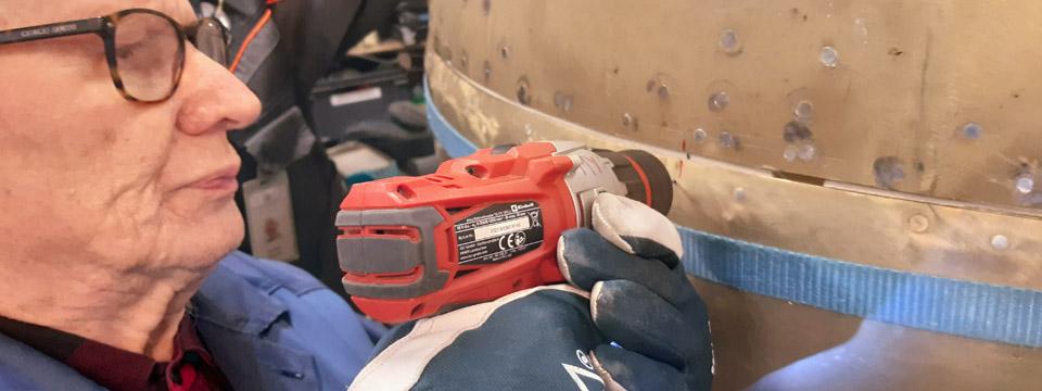
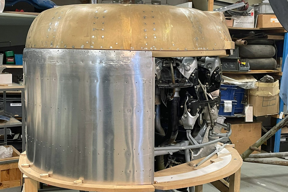
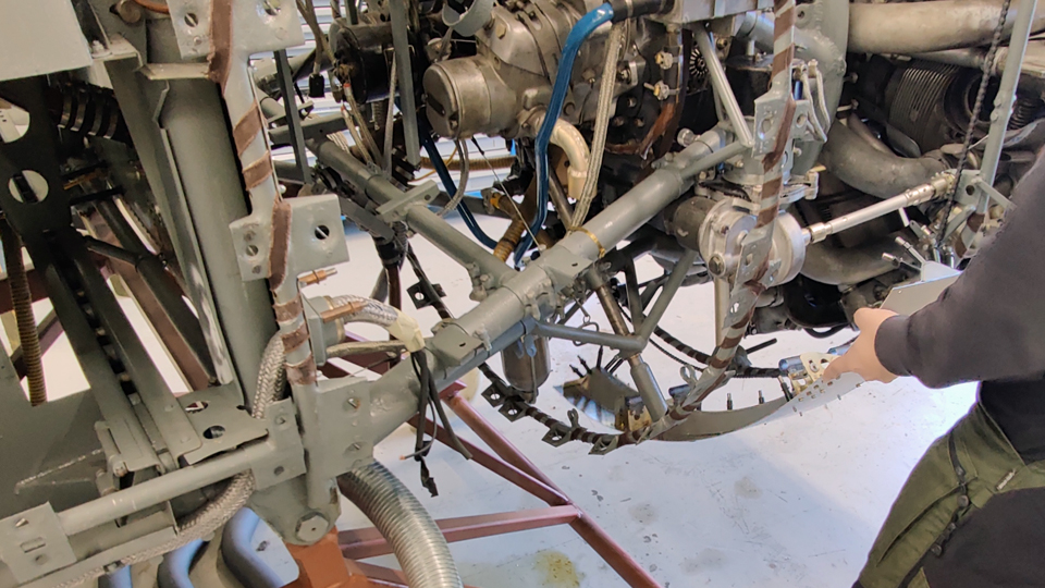
After the guides and guiding pegs had been fastened on the cowling, the cowling’s fastening to the NACA-ring was tested. The testing was done while the cowling was still fastened on the last where it was built. It was noted that the guiding pegs fitted expectedly to the holes drilled in the hem of the NACA-ring. Thus the NACA-ring was fastened in place on the Pratt & Whitney R-1830 Twin Wasp engine, after which the lower cowling was fastened from its upper edge to the NACA-ring and from its lower half to the fastening ring of the rear part of the engine. The engine is beginning to resemble that of the Myrsky fighter. Photos by Lassi Karivalo except if otherwise mentioned. Translation by Matti Liuskallio. |
|
Avainsanat: aviation history, restoration, MY-14, VL Myrsky, Tuesday Club |
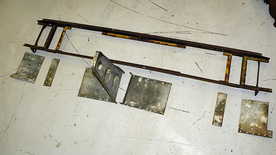
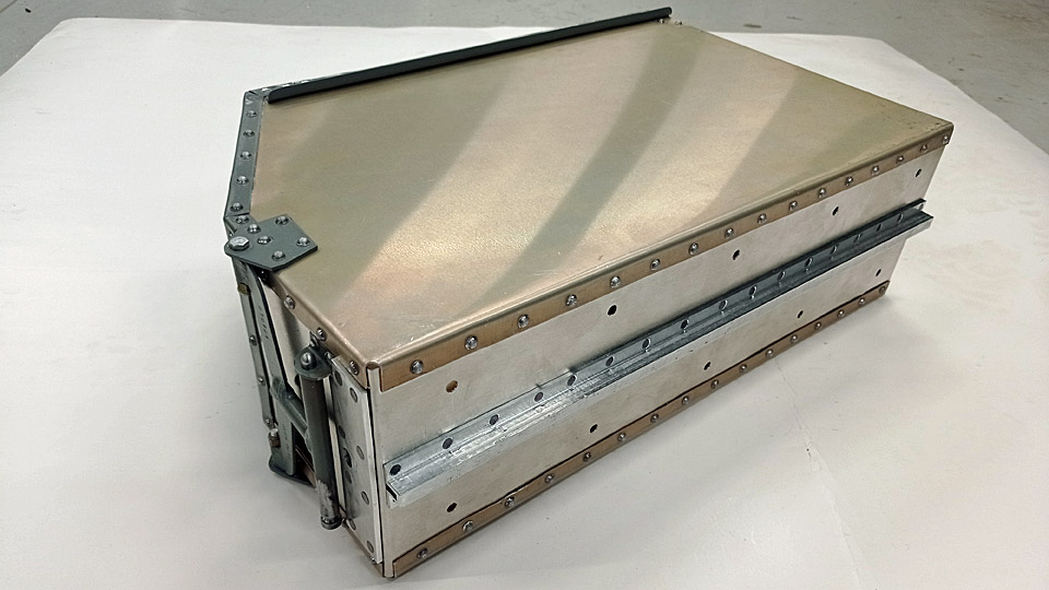
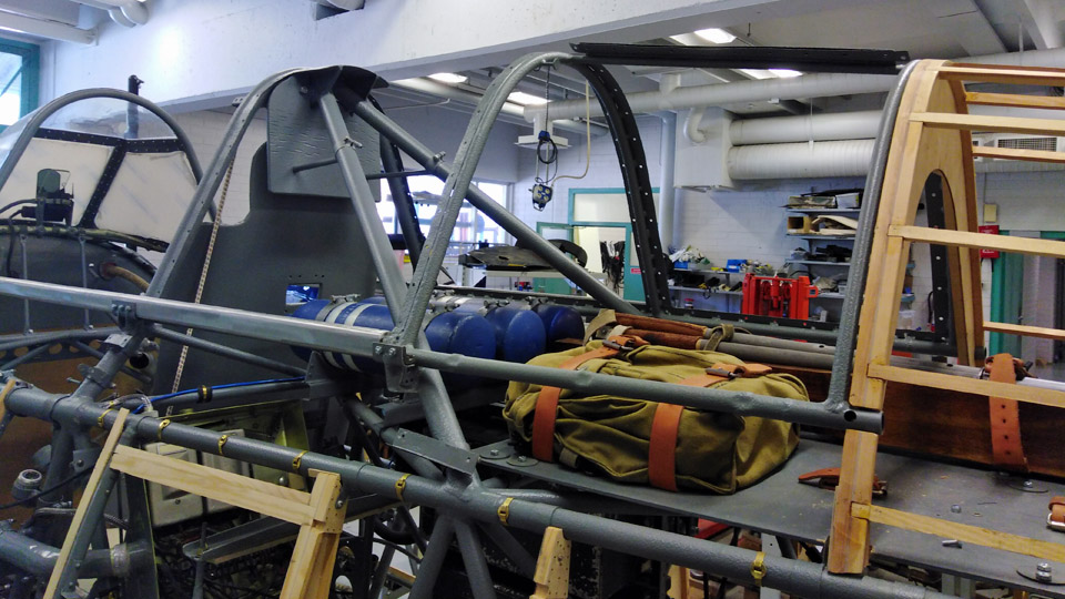
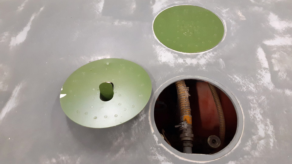
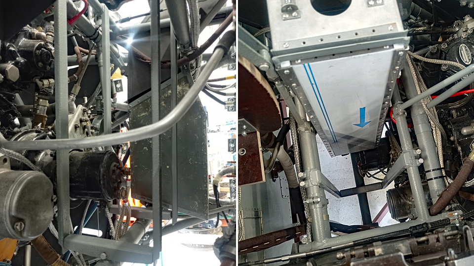
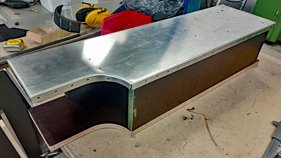
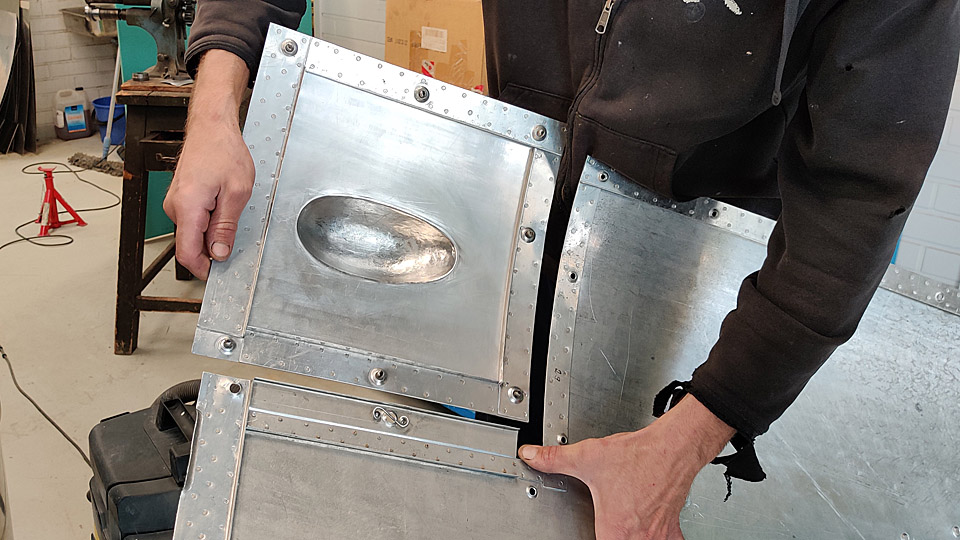
MY-14 lateral machine gun caissonsTorstai 14.12.2023 - Reino Myllymäki The armament of VL Myrsky II consists of four synchronized heavy 12,7mm VKT machine guns, located in the front fuselage. Each machine gun has its own caisson. The machine gun caissons in the middle hold 220 and the lateral gun caissons 260 rounds.
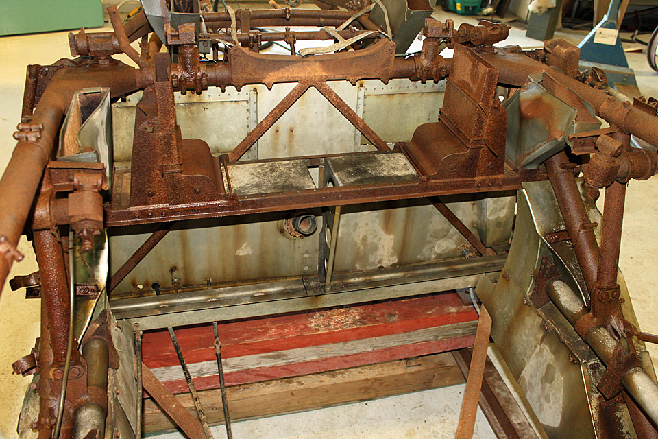
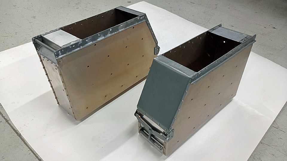
The VL Myrsky II restoration project has available three Myrsky fuselages (MY-5, MY-9 and MY-14). In all of them the original rails for the caissons were in place. In all these the rails were intact, but the steel parts were badly rusted. The original caissons couldn’t be found anywhere.
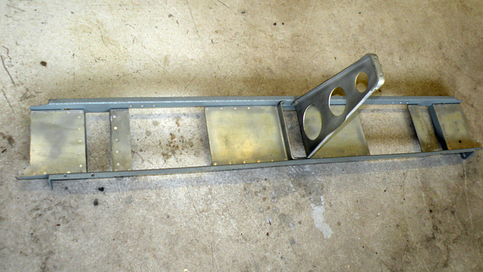
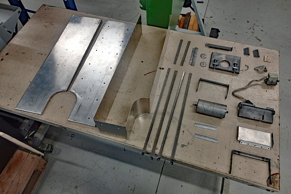
The MY-14 rails were picked out to be restored, dismantled from the fuselage and all the screws and rivets were taken apart. The rust from the steel parts was blown away with glass ball blasting, the surfaces were treated with Isotol-klarlack and painted grey. The aluminium parts were cleaned with glass ball blasting. The parts were riveted together again with aluminium rivets according to the blueprint, and the entity was painted grey all round. The refurbished rails were installed back to their original place.
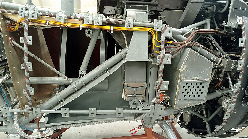
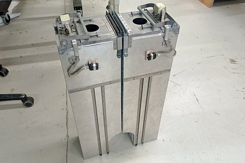
The entirely new caissons were made according to the blueprints. The blueprints lacked the detail picture of the rear handle, the necessary measurements were obtained from the assembly blueprint. The finished caissons turned out to be slightly too big and they didn’t fit properly into place. The matter could be corrected by adjusting the rails and hammering the caissons. The left-hand caisson remained a bit ill fitting. This was mostly because the left-hand adjustment screws of the rails couldn’t be properly reached. The locking of the caissons was observed to be working.
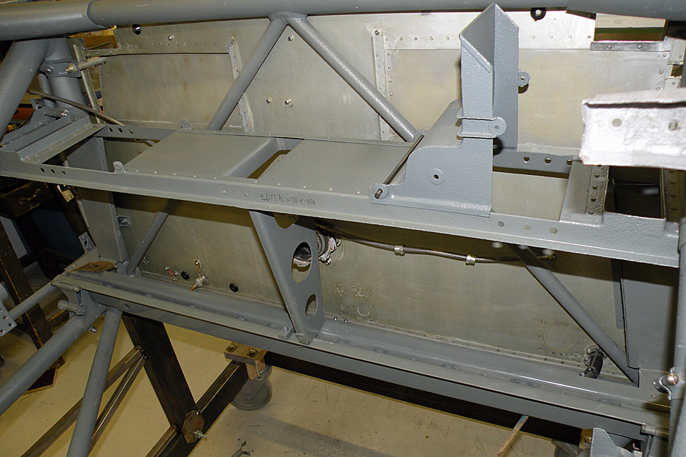
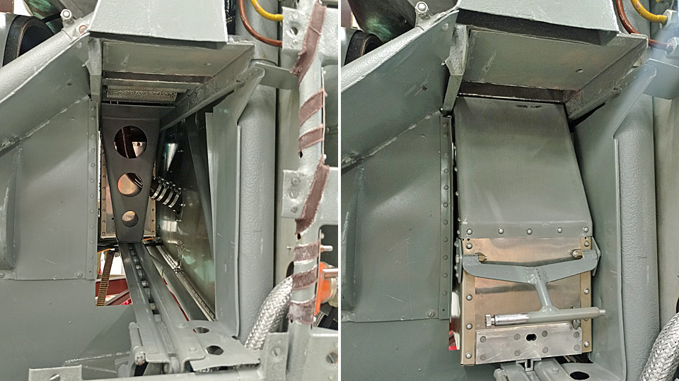
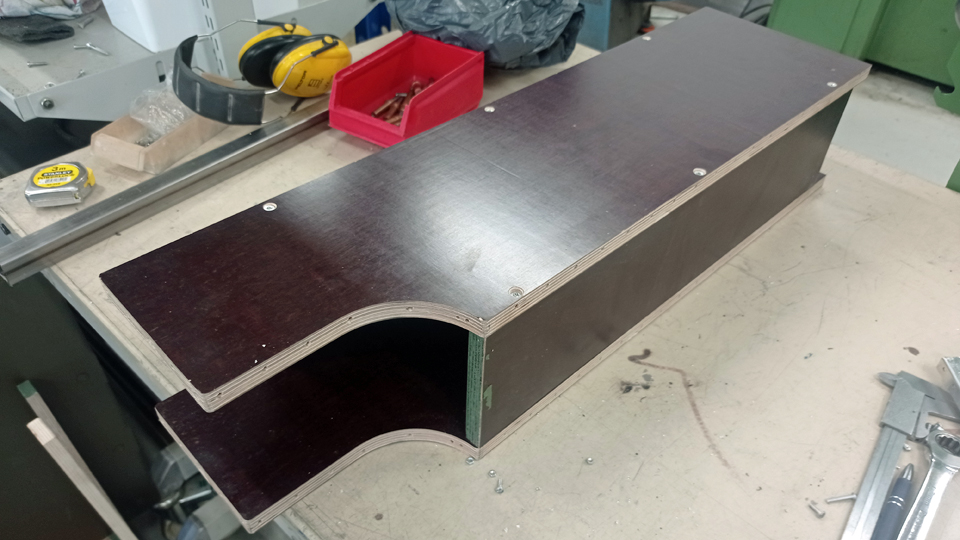
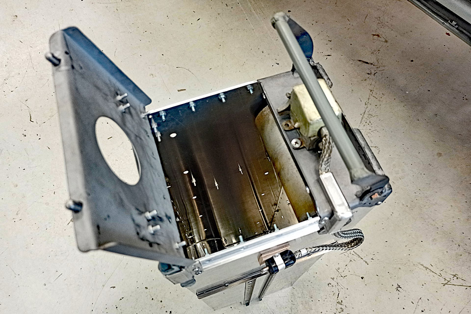
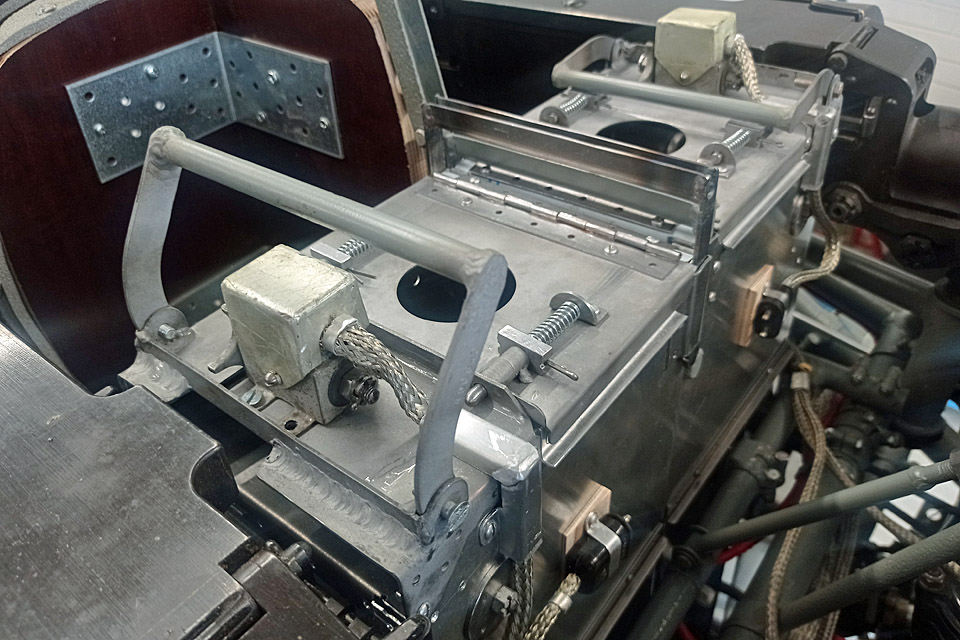
How the caisson is fitted into place and locked: The caisson slides to place on a roller rail. The locking lever in the lower rail is turned up, and with a screw in the lever the caisson is tightened into place. The handle of the caisson is turned down and a locking peg inside the handle locks the handle in the down-position. The square-shaped tip of the locking screw leans now against the handle of the caisson and prevents the locking screw from turning on its own account. The steel front plate of the caisson is meant to guide the spent cartridges, coming from the gun above, into the collection box.
The caissons will be painted grey all over later, at the same time as other larger parts are taken to be spray painted. |
|
Avainsanat: aviation history, restoration, MY-14, VL Myrsky |
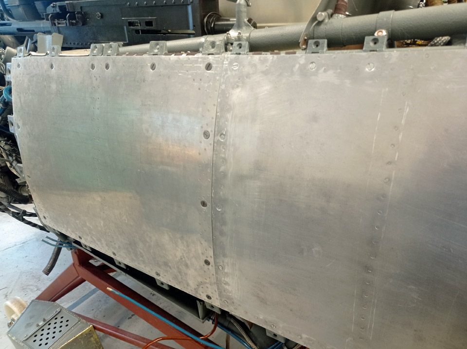
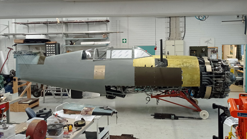
Making the lower sheet metal cowling for the Myrsky engineMaanantai 6.11.2023 - Tuesday Club member The VL Myrsky II (MY-14) engine has a lower and upper cowling, made of sheet metal. The lower cowling was built at the Tuesday Club. The cowling was made of 1 mm thick aluminium sheet. The stiffening formers that were fastened on the inside surface of the cowling were made of the same material. The upper engine cowling will be built at the Finnish Air Force Museum, where the main undertaking will be the restoration of the MY-14 fuselage.
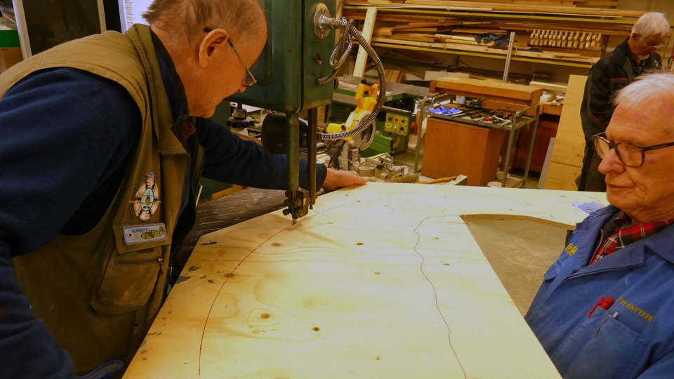
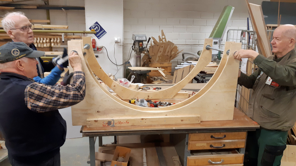
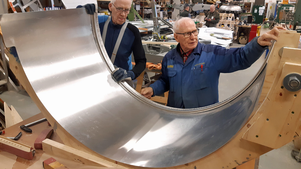
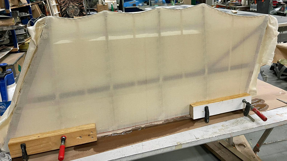
Before the 1 mm sheet, cut out of aluminium plate, was started to be formed into the U-form of the lower engine cowling, a female forming last was cut out of sturdy plywood. This forming last works as a model, showing that the lower engine cowling needs a curved shape. The shaping of the sheet was done by mangling the sheet in a mangler with three rollers and comparing the sheet to the forming last at intervals. After the mangled sheet had been made to press itself tightly against the forming last, it had reached its correct form. Next the formed sheet could be tried on the Pratt & Whitney engine used in the Myrsky. The engine was moved into the restoration shop in the Finnish Aviation Museum. We managed to fit it snugly on the side of the engine.
Photo by Heikki Kaakinen. The lower engine cowling needs several stiffening profile strips to keep it in form. The stiffening strips were cut and bent according to the programming information given at Prolaser Oy. After this we started to fasten the stiffening profiles on the inner surface of the engine cowling. The stiffening strips are fastened by riveting onto the metal casing.
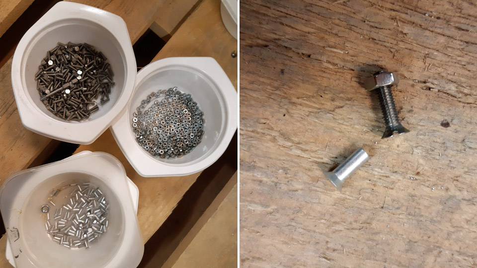
The Myrsky blueprints gave us the exact position of each profile strip on the inner surface of the engine cowling. So we started fastening the profile strips, but not straight with rivets but at first they were fastened in place with 12x3 mm small bolts. The holes for the bolts were drilled on the rivet spots according to the blueprints, and a small bolt was put in the hole to fasten the stiffening strip to place. When all the profile strips had been fastened, the inside of the engine cowling looked a bit like a porcupine, because the nuts of the small bolts were sticking out of the edges of the profile lists.
Now the engine cowling with stiffening profiles was fitted on the engine. The casing still settled laudably in place, so we could start fitting the fastening latches in the top part of the engine cowling. The lower and upper engine cowlings are fastened to each other with openable latches because the cowlings have to come off when maintaining the engine or armament.
Before we started changing the fastening bolts of the stiffening profiles to countersunk aluminium rivets, the outside holes of the bolts were countersunk to suit the flush rivets. The profile strips were riveted, one hole after the other, onto the engine cowling’s inner surface with 8x3 mm aluminium rivets. The riveting was done with a riveting pin and a counter part pressed on the rivet head on the opposite side.
Finally it was checked that the flush heads of the rivets had been riveted flush with the engine cowling surface. Some rivet heads had to be tapped with a hammer flush with the engine cowling surface, so that the outside surface of the cowling was left absolutely smooth after the riveting. The finished lower engine cowling will still be chromated, the same way as all the Myrsky aluminium parts. Photos by Lassi Karivalo expect if otherwise mentioned. Translation by Matti Liuskallio. |
|
Avainsanat: aviation history, restoration, MY-14, VL Myrsky, Tuesday Club |
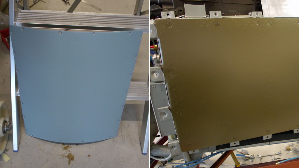
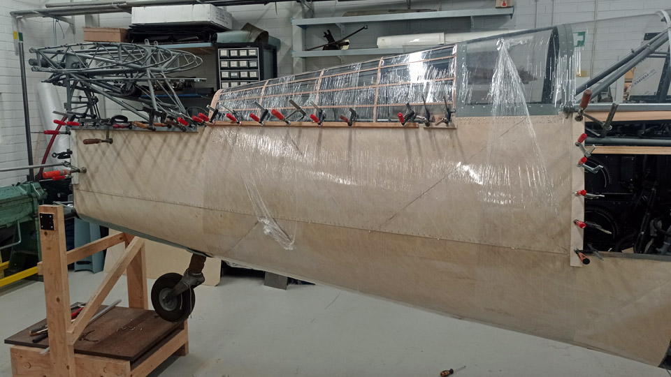
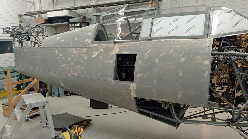
MY-14 rear fuselage coveringSunnuntai 29.10.2023 - Reino Myllymäki The rear fuselage plywood covering of the three fuselages (MY-5, -9 and -14), which were at the disposal of the VL Myrsky II restoration project, has completely disappeared, so the MY-14 received a completely new covering. The MY-14 belonged to the so-called main series (Myrsky II) and the blueprints for its rear fuselage have disappeared. The early blueprint of the prototype (Myrsky), the test series (Myrsky I), and the early main series, used for the MY-5 and MY-6, has been preserved. According to it, the rear fuselage has been covered with 1,2 mm shreds of diagonal plywood joined with scarf joints. By examining photographs a means of covering used in later main series aircraft was found. There seven diagonal plywood sheets were used, with grading in the horizontal seams.
Because diagonal plywood isn’t available, we made it by joining together plywood sheets sawn into triangular shape and glued with scarf joints. The sheets obtained in this way were roughly sawed into shape and then fitting them to final measurements. Gluing was done with Gorilla Glue and the necessary pressure was obtained by using stretch film, clamps at the edges and staples in other places. Originally the staples were used at 20 mm partition.
For the first plywood sheets the inner painting was done after the gluing, but the last ones had to be painted before gluing. In the latter case the patches to be glued were drawn on the plywood and only the areas between the lines were painted beforehand. After the gluing the remaining areas were painted, if possible. The used paint was Temalac by Tikkurila and the shade was RAL 7005.
External priming was done according to the original advice with alkyd primer, where about 50% aluminium powder was added to the first layer. After this the fuselage was painted twice over with the same paint but without the aluminium powder. Between the coats of paint the surfaces were given primary sanding and puttied where necessary, using Spakkeli which is the Tikkurila wood putty. As a primer Futura 3-solvent thinned primer, shade RAL 7005 was used. The blog is based on the report and photographs produced by the Finnish Air Force Museum restoration group. Translation by Matti Liuskallio. |
|
Avainsanat: aviation history, restoration, MY-14, VL Myrsky |
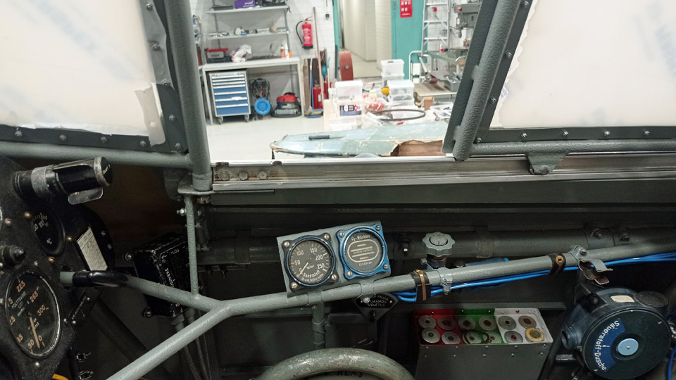
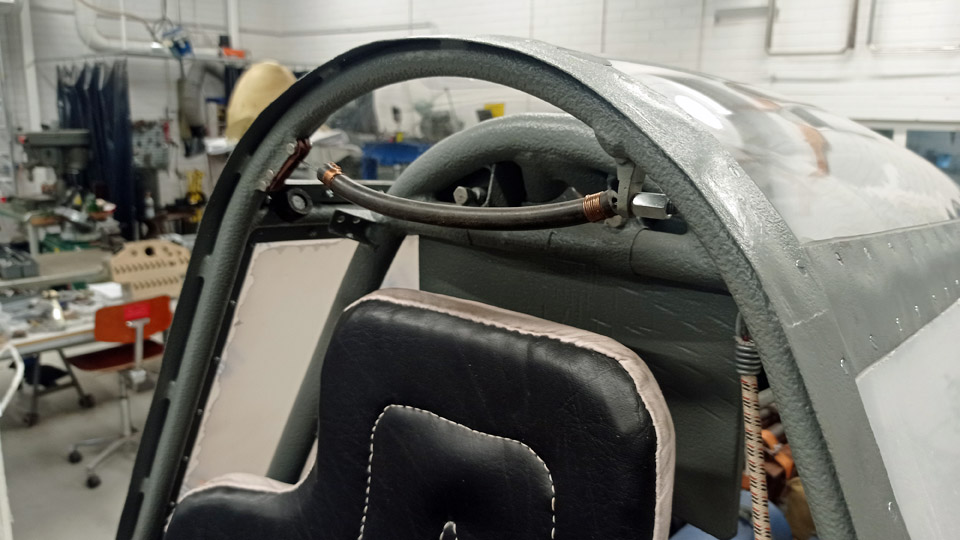
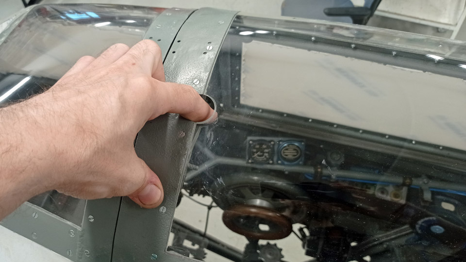
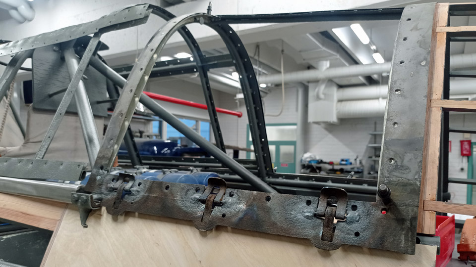
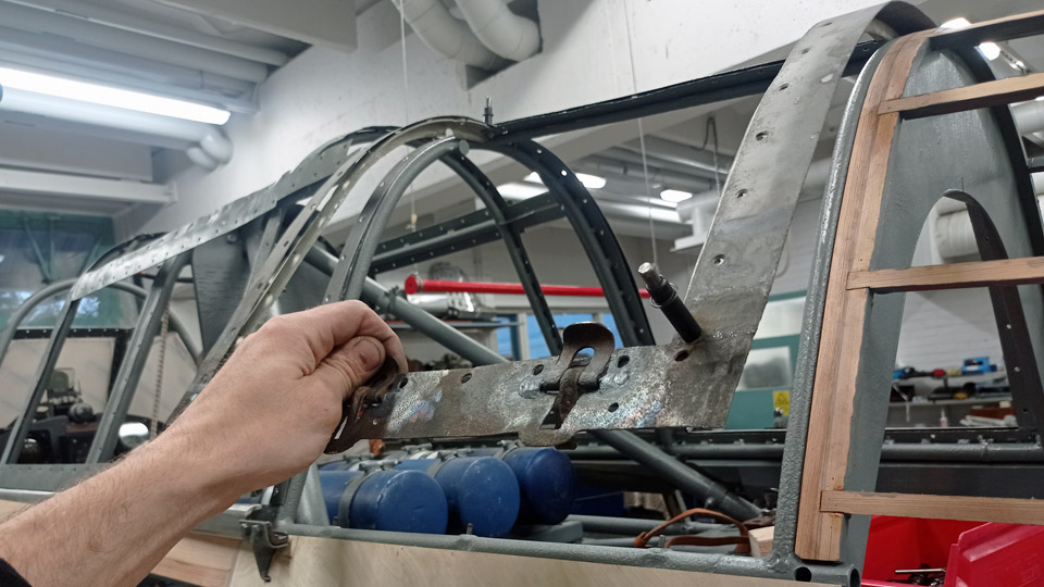
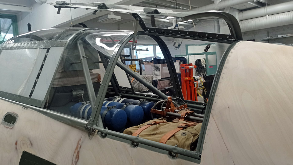
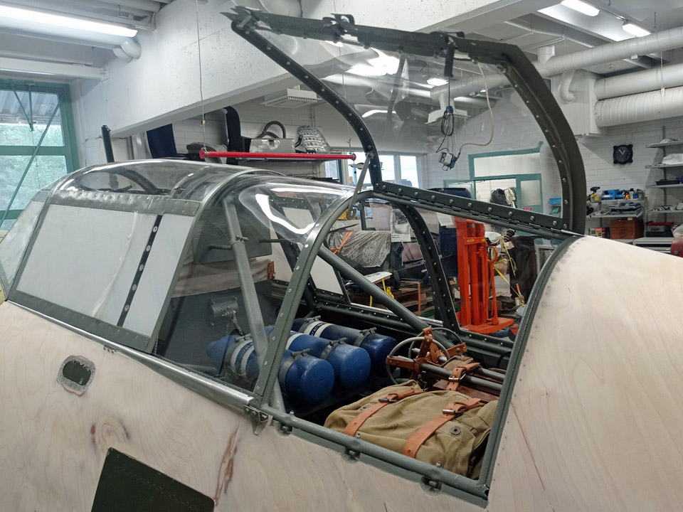
The MY-14 sliding canopyTiistai 10.10.2023 - Reino Myllymäki The original sliding canopy of VL Myrsky II MY-14 has disappeared. However, we had at our disposal two original but badly corroded sliding canopies with all their parts remaining. The plexiglass parts were, however, destroyed.
The sliding canopy which had been chosen to be restored was taken apart and we noticed that total corrosion hadn’t taken place. So the canopy frames were sandblasted and painted grey. The bearings of the sliding mechanism were replaced with bearings of original quality. For some reason the sliding mechanism didn’t work with the new bearings before the outer rim of the bearings was honed slightly narrower.
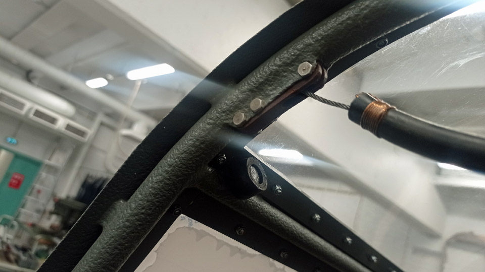
The locking peg, which moved inside the canopy frame, was rusted solid and the wire moving the peg was cut off. The old locking peg was removed and replaced with a new one, lathed according to the blueprint. A reinforced peg was made, according to modification amendment C 301, because the original peg in the frame was of that model and the locking slots in the runner were measured for the reinforced peg.
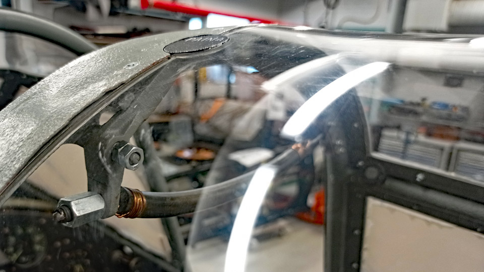
The wire inlet/guide piece was in a poor shape and was replaced with a new one, made of parkesine according to the blueprint. A new wire was soldered to the locking peg and an end piece was made to the wire according to the blueprint, and a piece of rubber hose, which worked as the handle was attached with brass string. The original lever for the opening mechanism, cast in brass and the aluminium press button at the end of the lever were cleaned, and the lever was painted grey, the press button black. The “PRESS”-text engraved at the end of the press button was nearly vanished. The engravement was repaired where needed and the text was painted white.
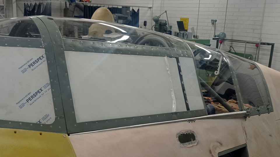
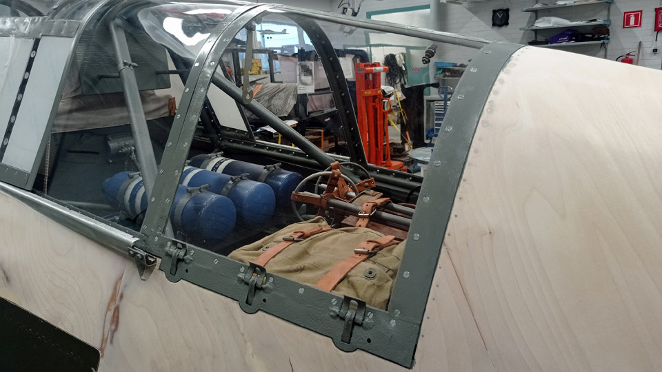
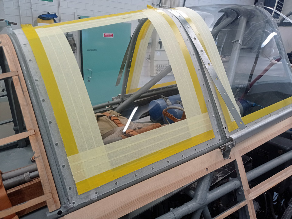
The new bent canopy plexiglass panes were sawn into measure and the necessary rabbets were milled and ground, so that the panes settled flush with the canopy frame strips. The original inner plexiglass aluminium holder strips were cleaned with oxalic acid and painted grey. The plexiglass panes were fastened with new 3 mm screws and nyloc nuts. A suitable hole was made into the canopy’s top plexiglass pane to give access the opening press-button.
The original aluminium strip at the rearmost end of the canopy was badly corroded and broken, so a new strip of 0,7 mm aluminium plate was made according to the blueprint. According to the blueprint there should be a seal made of felt at the front end of the canopy, but according to photographs it seems that it has never been fitted there, so we left it out, too. The blog has been edited from the report by the Finnish Air Force Museum’s restoration group. Photos by the Finnish Air Force Museum. Translation by Matti Liuskallio. |
|
Avainsanat: aviation history, restoration, MY-14, VL Myrsky |
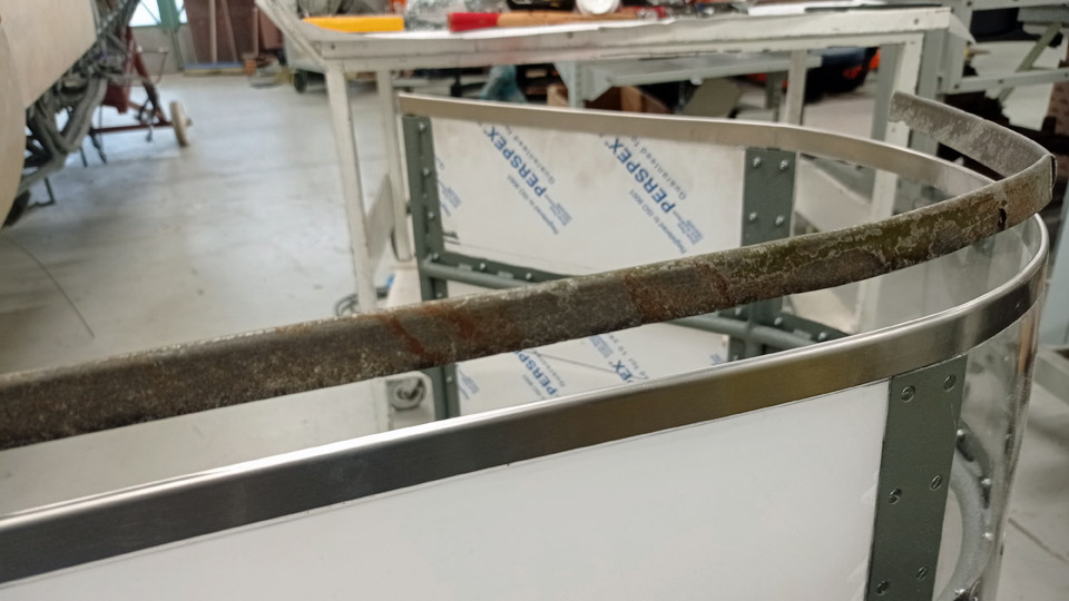
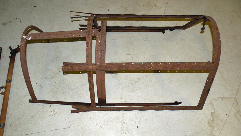
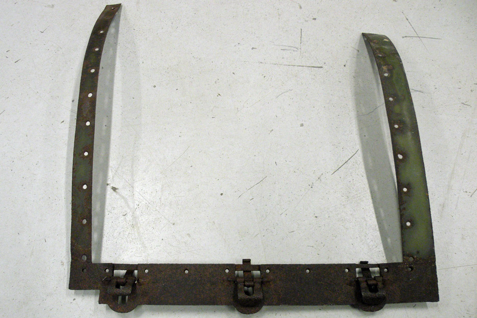
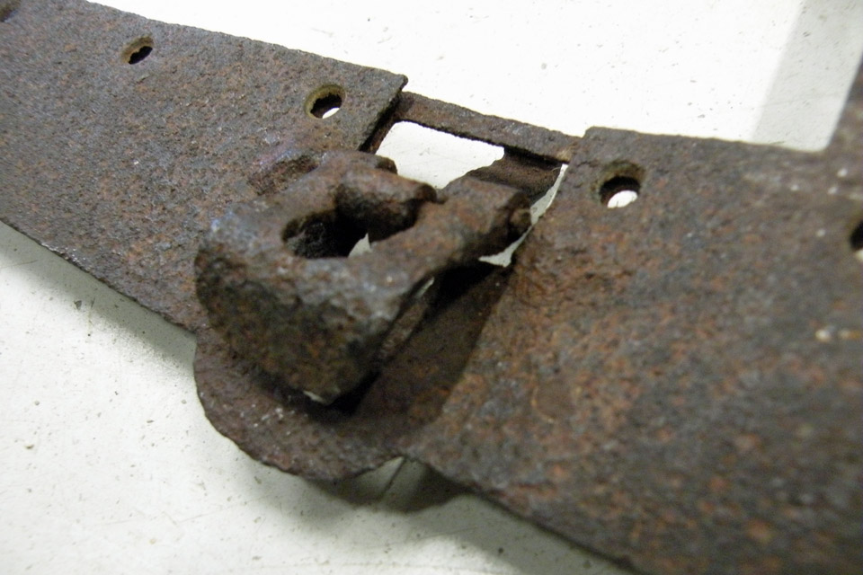
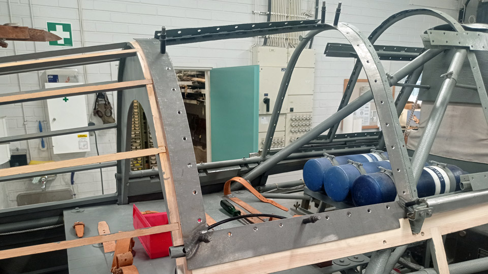
The MY-14 canopy rear panesSunnuntai 8.10.2023 The VL Myrsky II MY-14 canopy’s rear pane frames with their fastening strips have been preserved but are badly corroded. The frames of the opening hatch have remained as separate parts. The plexiglass panes have all been destroyed.
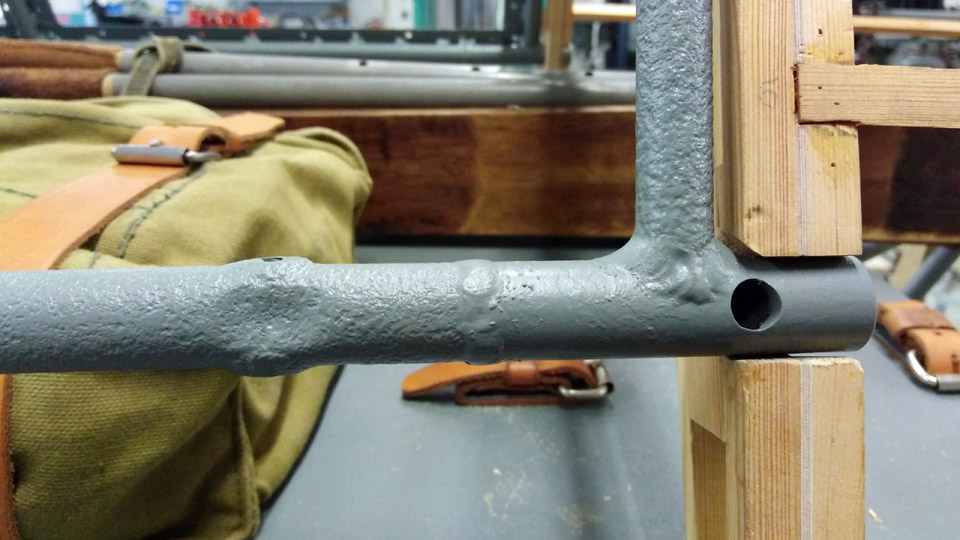
The rear pane frames were sandblasted from rust. The front and rear fastening points were thoroughly corroded, so replacement parts were welded from new tube.
After repairs the frames were painted and fitted back to place. Some of the plexiglass fastening steel strips were badly corroded and they were replaced with new strips. The axles of the opening hatch locking bars, made of piano wire, were broken off so they were removed, and new axles were welded to replace them. The aluminium strips inside the hatch were bent and cracked, so they had to be straightened and repaired by welding. All the strips and the opening hatch frames were cleaned of rust and painted grey.
The plexiglass panes were cut to measurements and fitted into place. Rabbets were milled and ground in the plexiglass panes, so that the fastening strips settled flush with the plexiglass panes. The plexiglass panes were fastened with new 4 mm screws and nyloc nuts.
The original aluminium locking clasp for the openable hatch was in good condition, so it was only cleaned with oxalic acid and refitted to place. A hole for the antenna wire was made in the right-hand side rear pane. Photos by Finnish Air Force Museum. Translation by Matti Liuskallio. |
|
Avainsanat: aviation history, restoration, MY-14, VL Myrsky |
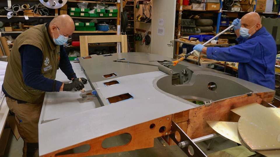
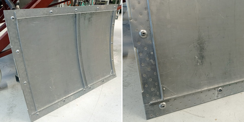
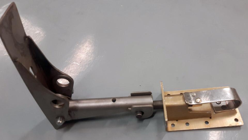
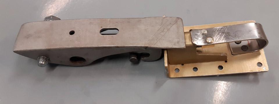
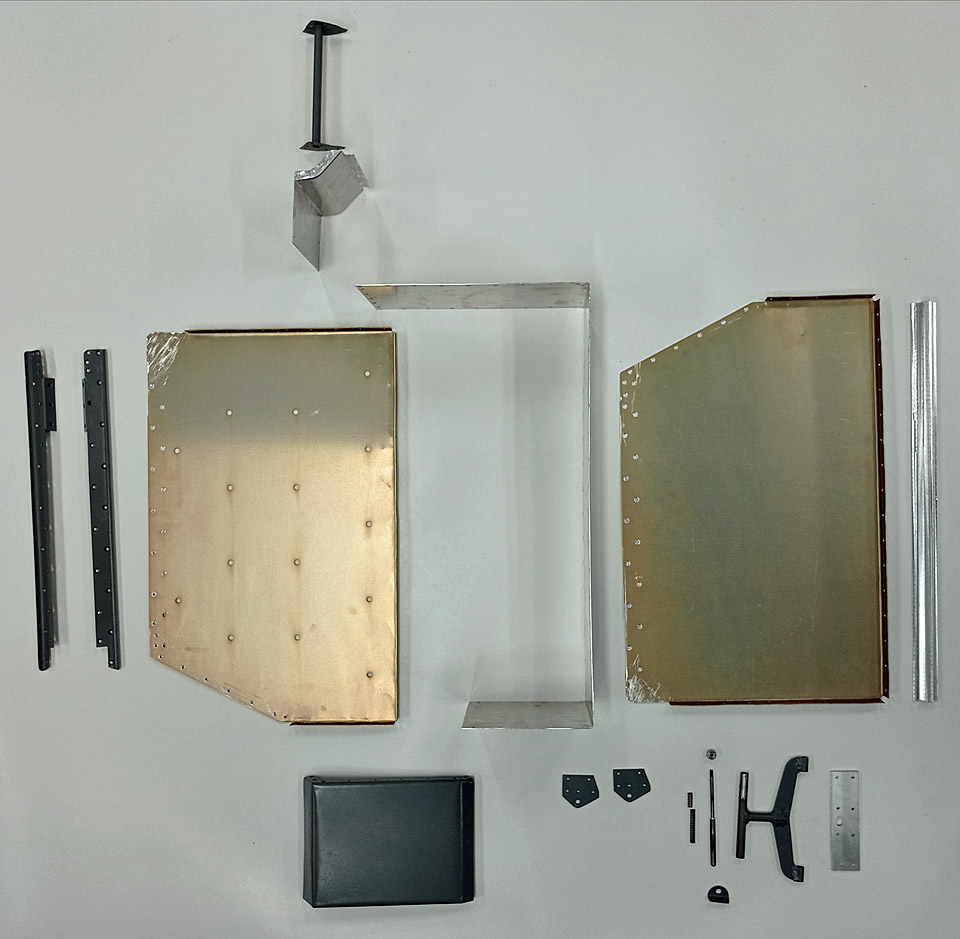
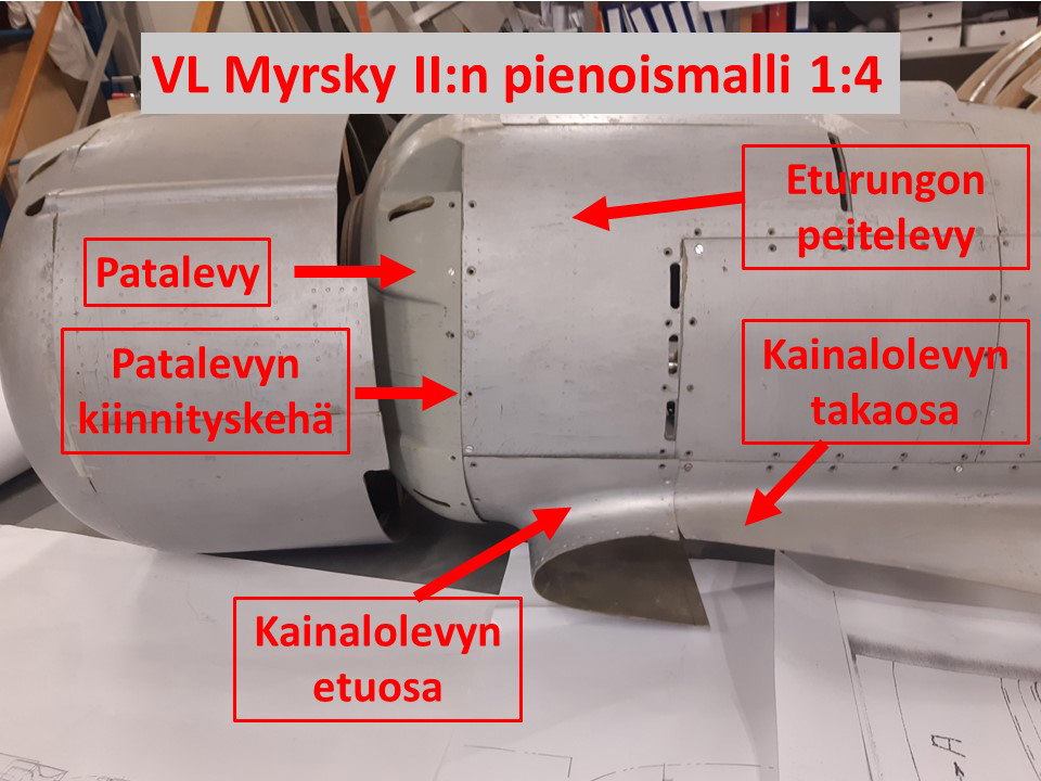
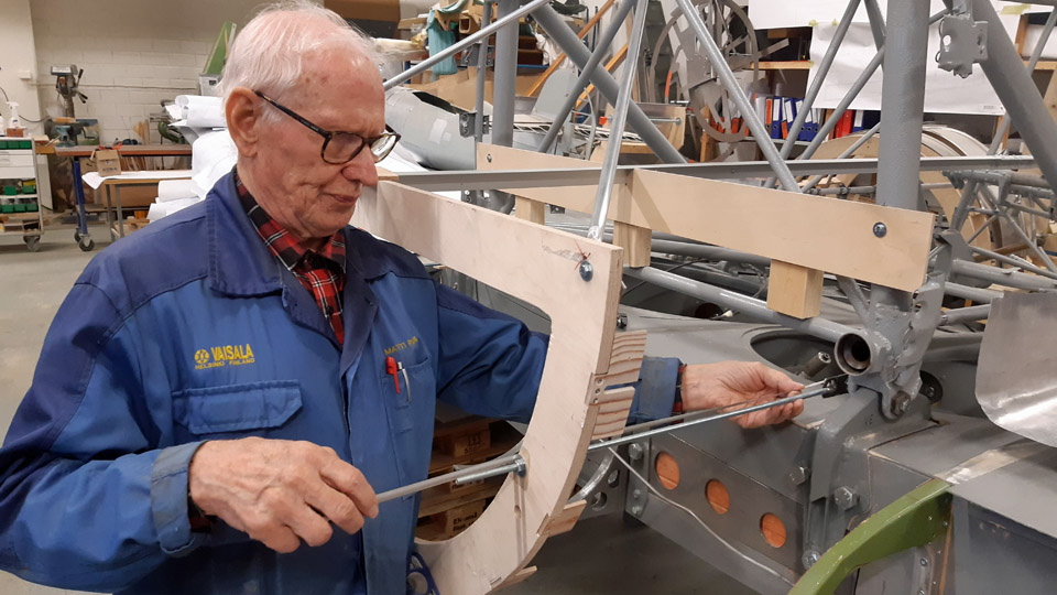
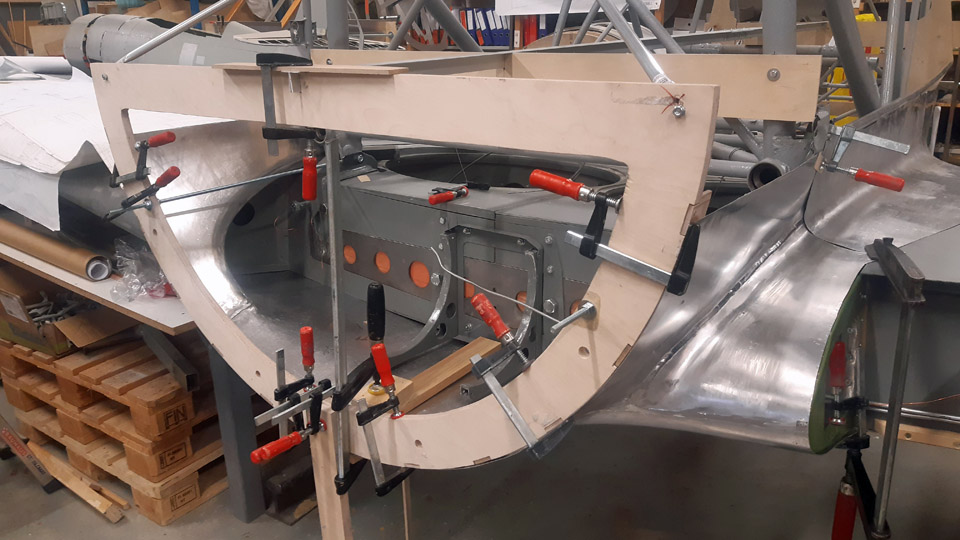
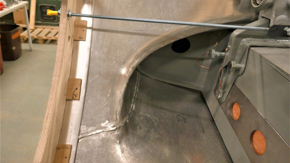
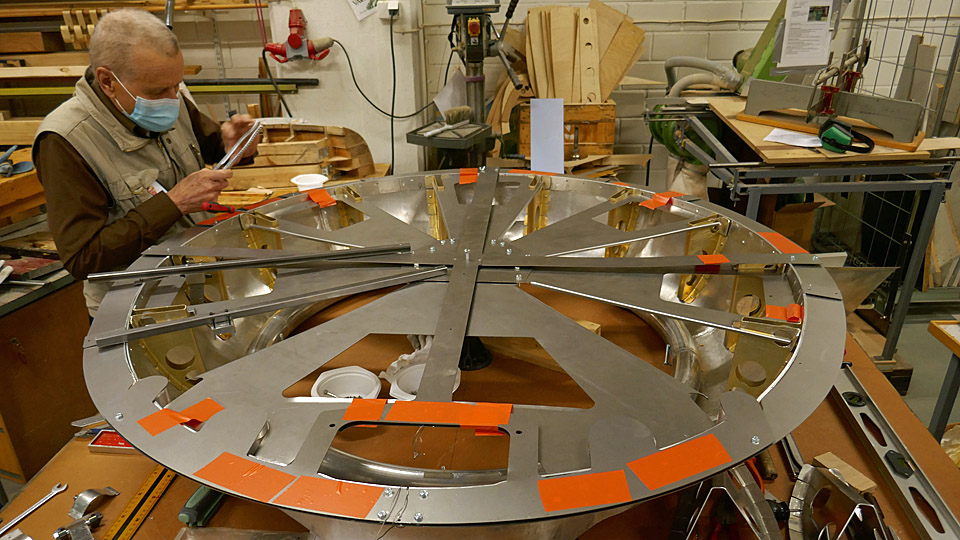
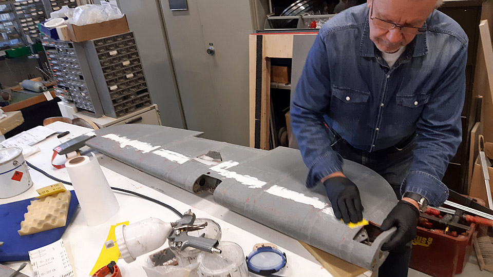
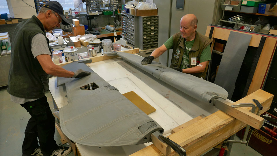
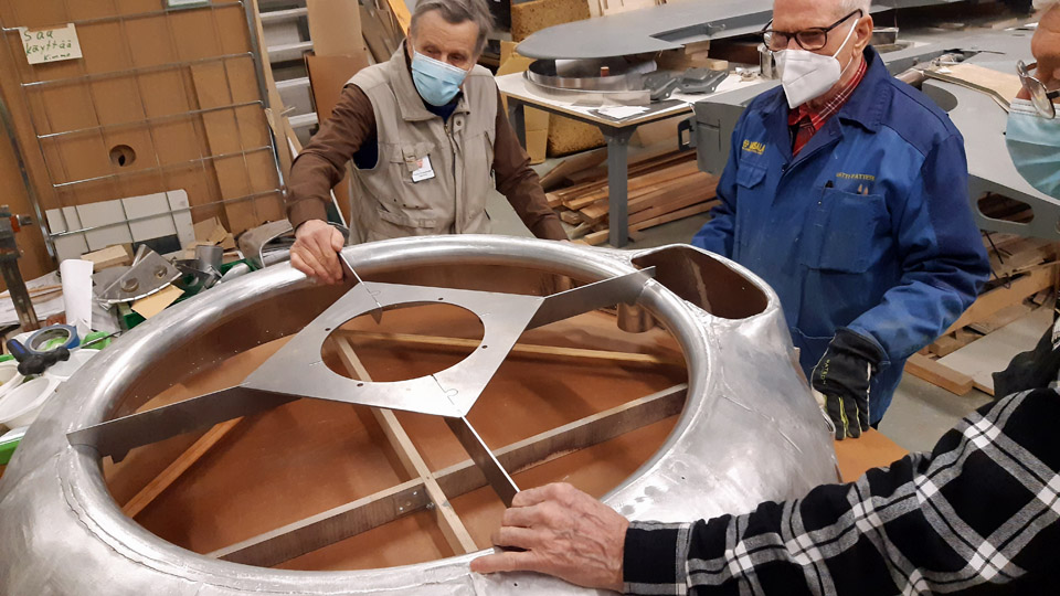
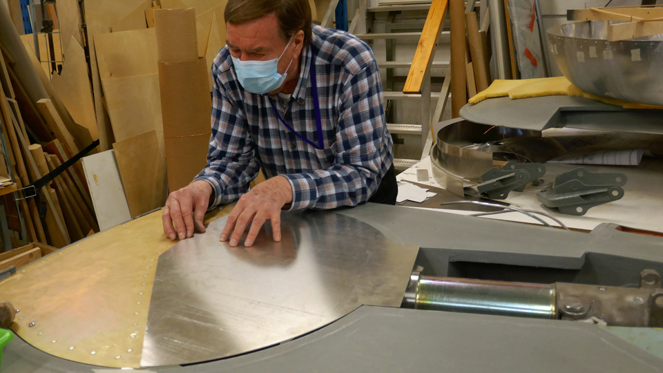
Fitting the front parts of the Myrsky wing root fairingsSunnuntai 1.10.2023 - Tuesday Club member The wing and fuselage seam is covered in the VL Myrsky II blueprints by sheets called the wing root fairings. The Myrsky wing root fairings are made of thin aluminium sheet. The Myrsky wing root fairing consists of two parts. The rear part covers the seam from the main spar to the trailing edge of the wing. The front part of the fairing in turn covers the area from the main spar over the leading edge of the wing to the lower surface of the wing and fuselage, reaching the main spar. The edges of the right-hand and left-hand wing root fairings meet under the fuselage in the centre line. The front parts of the wing root fairings are attached from their front edge to the tubular structure the heat shield’s fastening ring. To this same ring are also fastened the aluminium covering plates (engine cowlings) on the front fuselage, which can be opened. The fitting of the wing root fairing front parts, made during the restoration process of the Myrsky II MY-14), is underway at the Tuesday Club. This phase was made possible when the Myrsky MY-14 wing and the MY-5 fuselage frame were joined, to test the fitting of the wing to the fuselage frame. To fit the front ends of wing root fairings in place, we didn’t have the abovementioned fastening ring of the heat shield at our disposal. The MY-14 heat shield with its original fastening ring has already been assembled to the MY-14 fuselage under restoration at the Finnish Air Force Museum. We solved the problem of the lacking fastening ring by building a ring of sturdy plywood to the measurements of the original one. The plywood fastening ring we made must be assembled to the MY-5 fuselage frame we used for the test fitting of the wing, at exactly the spot corresponding the fastening ring of the heat shield. The reason for this is that the front parts of the wing root fairings could be fastened to the plywood ring the same way they will in their time be fastened to the actual heat shield fastening ring, which is presently at the Air Force Museum.
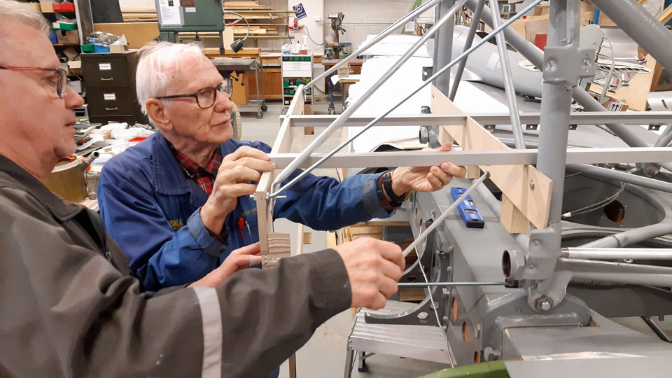
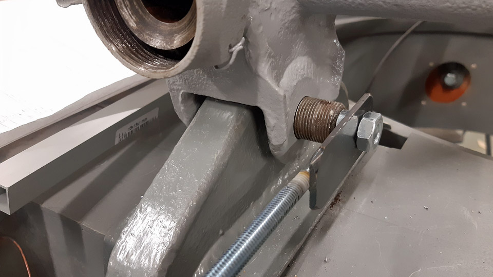
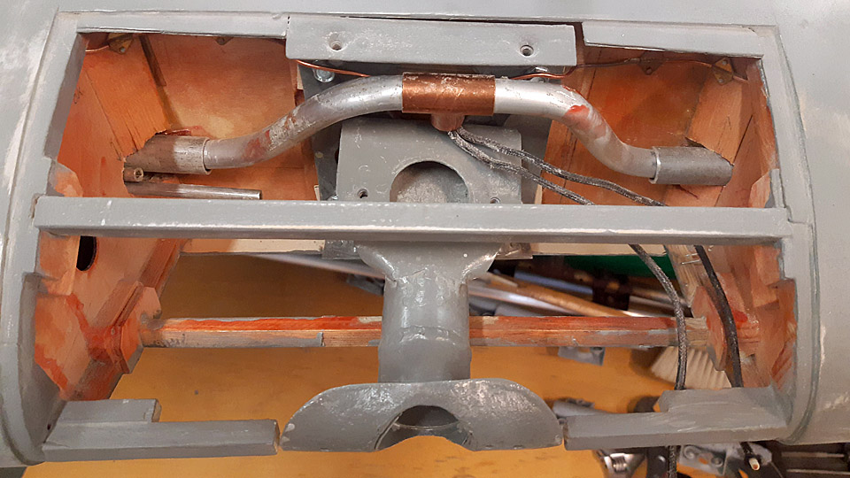
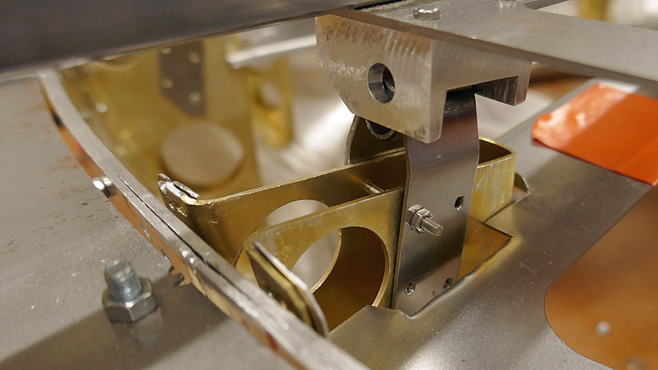
To measure the exact situation of the plywood fastening ring, which emulates the actual heat shield ring, we used the fuselage centre points marked in the Myrsky blueprints. The important one being point 51 of the fuselage centre, which is the centre point at the end of the transverse tube, located on the lower part of the front fuselage frame. From that point the three measuring points of the plywood ring were defined. They are the reference line in the fuselage centre line, formed by the metal tube, and the centre of the two bolts, which lock the wing to the fuselage frame.
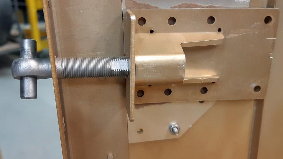
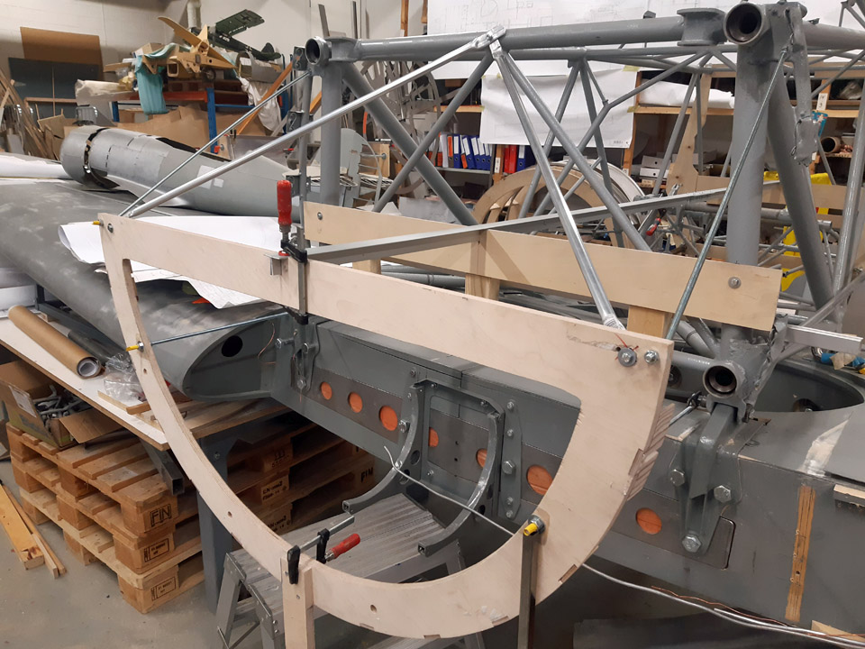
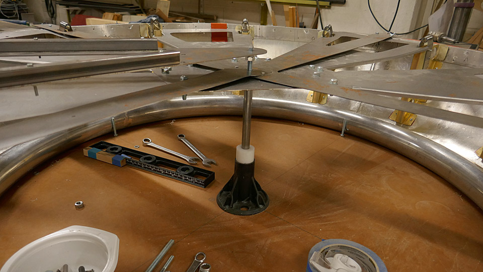
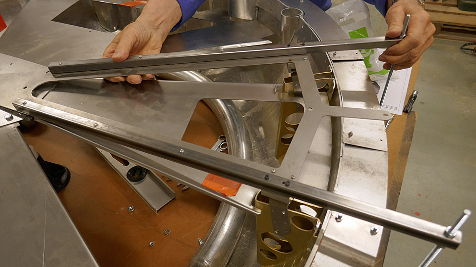
First the aluminium tube, which acts as the reference line was aligned to place. The top of the fastening ring was attached to the end of this tube. The plywood heat shield fastening ring was locked to the front bolts of the wing/fuselage joint with adjustable threaded rods from both sides. With the aid of these three fastening points the position of the plywood heat shield attachment ring could be defined to the millimetre in relation to the Myrsky fuselage frame. The top of the plywood attachment ring was propped to the fuselage frame with four metal supports, of which two are adjustable threaded rods. In addition the lower part of the attachment ring was propped to the floor.
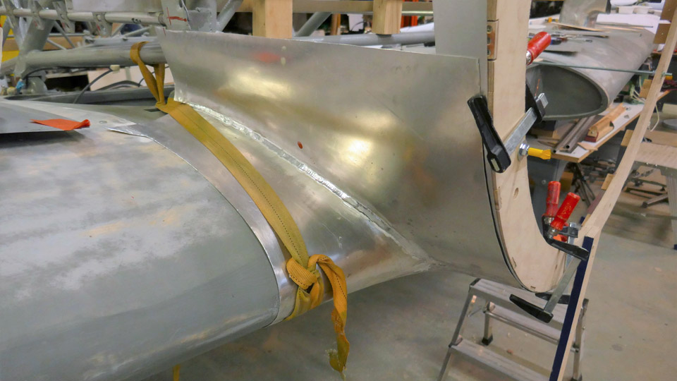
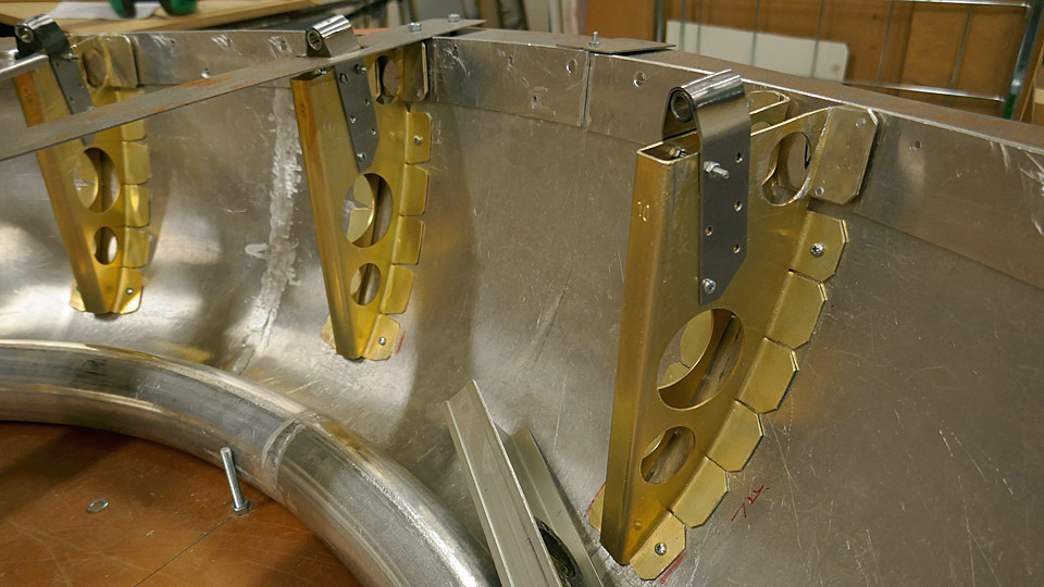
After the plywood ring was locked into place to the fuselage frame, the fitting of the front parts of the wing root fairings was started. The wing root fairing front parts were fitted to place in turns. They were attached first to the wing surface with cargo straps to keep the fairing tentatively in place during the fitting.
In the fitting, the wing root fairings were attached from their front part to the plywood attachment ring with clamps. It was noticed with pleasure that the aluminium sheet wing root fairings settled very well into place in relation with both the wing surface and the attachment ring. The front parts of the wing root fairings will finally be fastened to the fastening ring brackets with Dzuz-locks. In the test fitting of the wing root fairings the Dzuz-locks were replaced with plywood brackets, which were fastened to the plywood attachment ring. Because of the Dzuz-locks, a reinforcement ring will be made of aluminium sheet to the front edge of the wing root fairing. It has already been tentatively placed between the front part of the wing root fairing and the plywood brackets in the temporary fastening ring. Photos by Lassi Karivalo. Translation by Matti Liuskallio. |
|
Avainsanat: aviation history, restoration, MY-14, VL Myrsky, Tuesday Club |
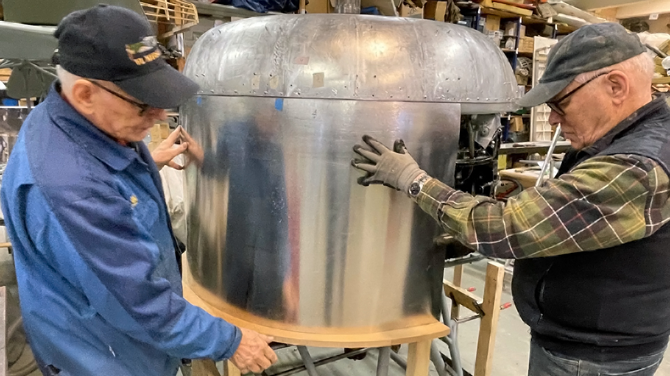
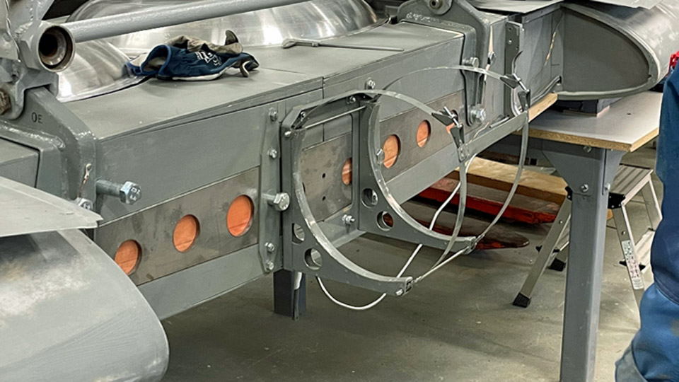
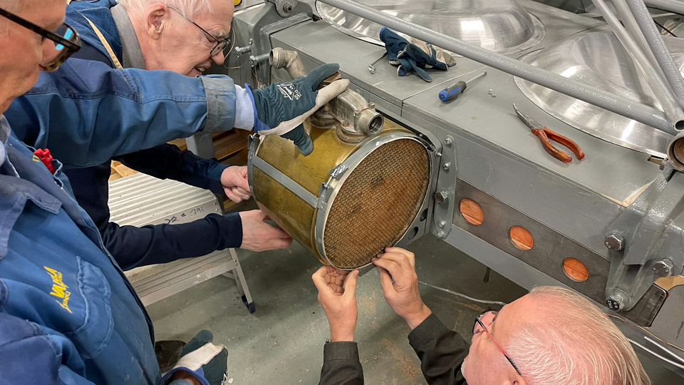
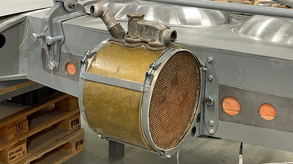
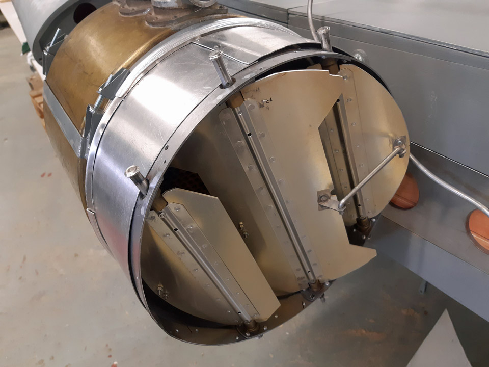
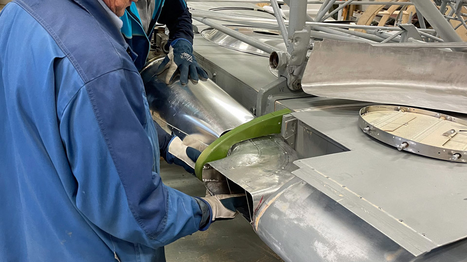
Time to test-fit the Myrsky oil coolerLauantai 19.8.2023 - Tuesday Club member Parallel with the fitting of the wing root fairings, the test-fitting of the barrel-shaped oil cooler was commenced. The Myrsky oil cooler is situated in the fuselage centre line, attached to the main spar “forehead”. Air comes to the oil cooler through an air duct from the left-hand wing’s leading edge. Respectively, after going through the oil cooler the air exits from the underside of the right-hand wing. For the MY-14 fighter restoration we have at our disposal an original Pratt & Whitney R-1830 Twin Wasp engine’s oil cooler, the very engine that powered the Myrsky. We received it from Airveteran Oy. Instead we have had to manufacture all the accessories for the oil cooler, including the ducts for the supply and exhaust air and the dampers adjusting airflow. The air ducts were made of 1mm thick, easily workable aluminium sheet. The pieces cut off the sheet were shaped in wooden shaping lasts, after which the seams were welded. We also made the dampers or gills that adjust the amount of air going through the oil cooler. The dampers adjusting the amount of supply air are controlled mechanically from the cockpit.
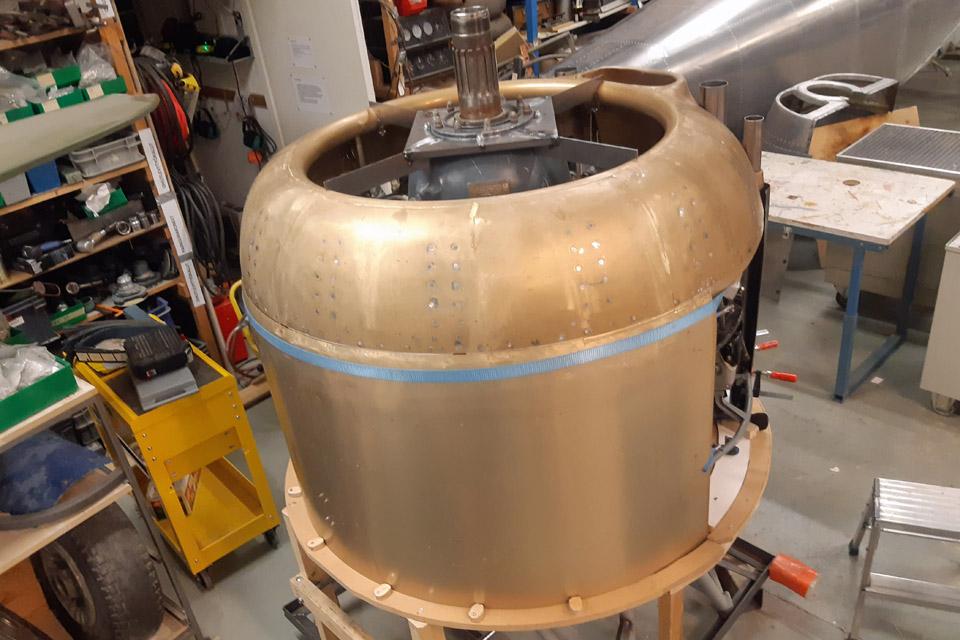
Photos by Heikki Kaakinen. Normally the oil cooler is permanently attached to the main spar. Because the MY-14 wing is made of two halves and the oil cooler is situated at the junction, the oil cooler must always come off, when and if the Myrsky will be dismantled for transportation to another museum or some other place to be placed on display. That’s why a handy rack with attachment straps was constructed. The oil cooler will be strapped on it and the rack is easily detachable from the wing spar and can also easily be reattached.
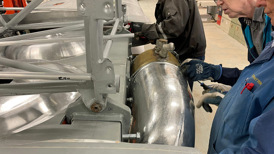
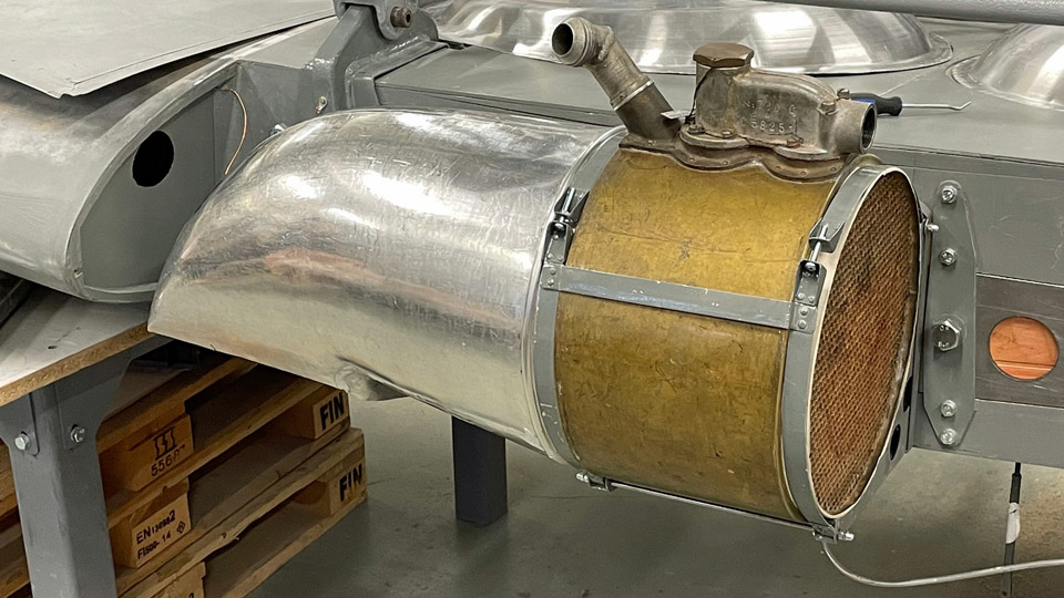
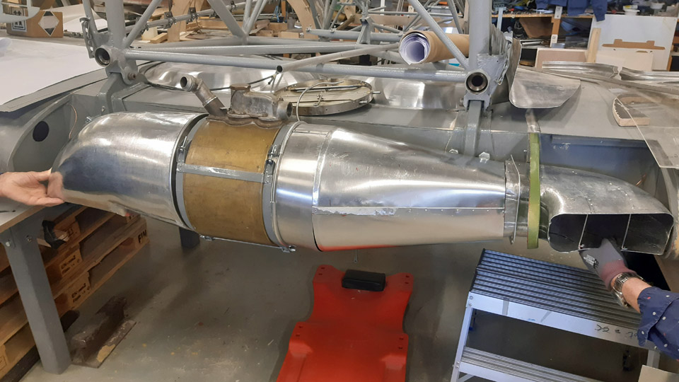
Photos by Heikki Kaakinen The test-fitting of the oil cooler was started by attaching the oil cooler attachment rack on the junction of the wing halves. The oil cooler was tightened to the straps. After that the cooler’s right-hand cooling air exhaust duct was fitted into place. The duct opens to the underside of the right-hand wing’s leading edge.
Photo by Heikki Kaakinen
The gills adjusting the incoming airflow were attached to the other end of the oil cooler. The gills are situated between the oil cooler and the supply air duct. The duct for incoming air is twofold. One end of the duct’s straight part is attached to the supply air damper and the other end to the front end of the L-shaped supply air duct. The opening of the incoming air duct is situated in the right-hand wing’s leading edge. There’s still work to do in fitting the oil cooler parts before every part is settled in its place as planned. A veritable “collection of gadgets” this Myrsky oil cooler system has proved to be.
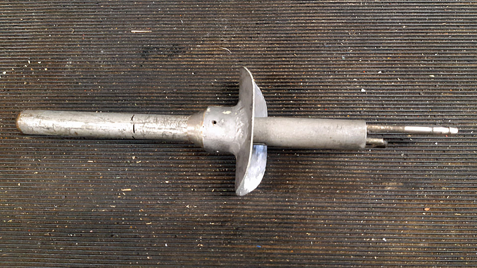
The pitot-tube, which measures the airspeed of the aircraft and is situated on the left-hand wing, was also test-fitted. The pitot-tube rack has been in place for long in the left-hand wing’s leading edge. We noticed, to our chagrin, that the 300 mm pitot-tube at our disposal was of a wrong length. It should be of the 500 mm long type. This can be seen in the Myrsky blueprints and photos taken of the Myrsky. Might there be a pitot-tube of the right length for us in the collections of the Finnish Air Force Museum?
Along with all other tasks numerous inspection hatches on the wings are being fitted into place. We had to grind the collars of the hatches a bit deeper, so that the hatches would become flush with the wing surface. Photos by Lassi Karivalo except if otherwise mentioned. Translation by Matti Liuskallio. |
|
Avainsanat: aviation history, restoration, MY-14, VL Myrsky, Tuesday Club |
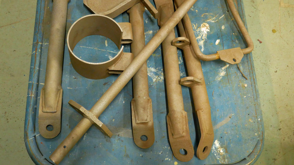
MY-14 midmost machine guns got caissonsKeskiviikko 12.4.2023 - Mika Rautasaari and Reino Myllymäki The VL Myrsky II had four heavy VKT 12,7 LLk/42-machine guns in the upper half of the forward fuselage. The machine guns were copies of 13,2 mm FN-machine guns, as the result of Swedish-Finnish illegal co-operation. They had been adjusted to the 12,7x99 NATO cartridges, which were already in use in Finland in the Brewster 239 fighters’ Colt MG 53-machine guns. Of the four machine guns, the caissons for the two midmost ones housed 220 rounds each. For the MY-14 restoration, it was a key issue that the innermost caissons, nor the mounting rails for the starboard one, hadn’t survived. However, the mounting rails for the port caisson were found, as was the lower support. Apart from that, the electric ammunition counters and the ammunition belt feeders’ guiding steel rolls, which had remained in the feeding chutes of all the three of Myrsky’s lateral machine guns, could be found.
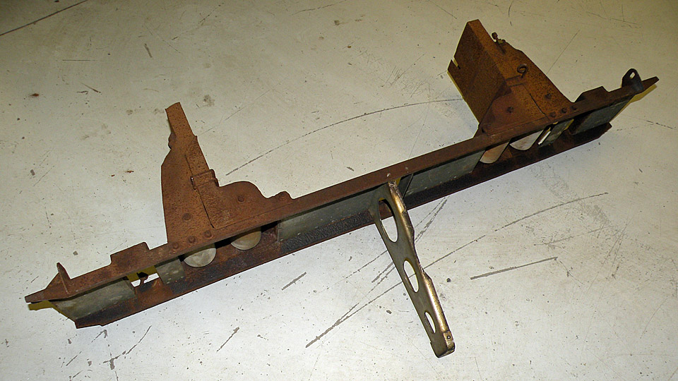
The original port side mounting rails and the lower support were blasted free of rust with glass balls, covered with Isotrol and painted grey. For the starboard side, new rails and the lower support were manufactured from steel according to the original blueprints. The lower support has threaded elevation adjustment.
The sides of the caissons were cut for us from 1 mm aluminium sheet with laser to the measurements in the blueprints, as were parts for the lid and handles. The edges of the caisson sides and the flanges that were cut from aluminium sheets, were bent to shape with a mould made of plywood.
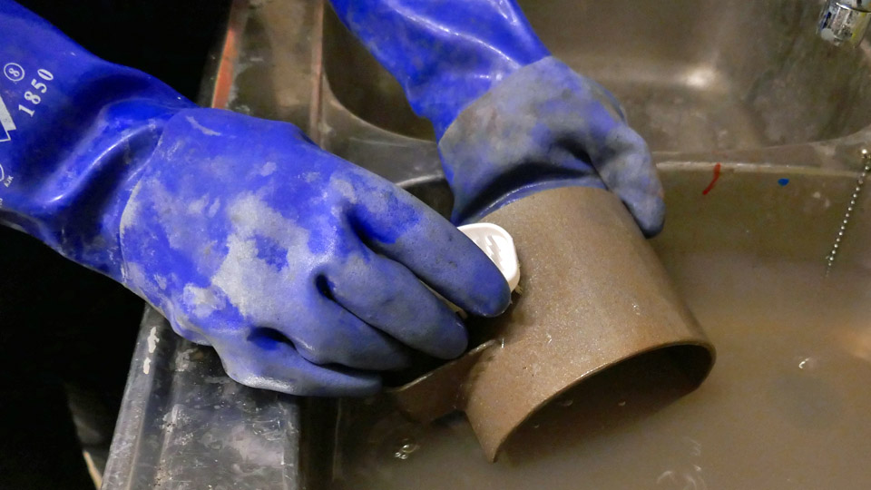
The original steel rolls guiding the ammunition belt feeding were cleaned with phosphoric acid and steel wool and the roll bearings were cleaned and greased. The ammunition counters had already been refurbished earlier, along with the assembly of the feeder chutes of the lateral machine guns. The refurbished rolls were installed inside the caissons, with the new belt guiding plates made of steel.
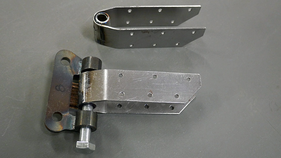
The lids of the caissons and the handles that could be turned to an upright position, were made of steel plates according to the blueprints. The lids were fitted with spring loaded latches and a hinge made of steel, and the ammunition counters were installed. A cover for the ammunition counter wire was made of aluminium according to the blueprints. Furthermore, an elevation piece of plywood was made for the connector, into which the ammunition counter connector was coupled with a collar made of aluminium. Guiding pieces of steel were made to the sides of the caissons to hold them in position on the installation rails.
The caissons were test assembled with screws and installed to the fuselage for the final assembly of the guiding rails. When the guiding rails had been fitted into place, the previously repaired attachment latches for the cases could be adjusted into the right place. The latch settles into the groove of the inner handles. The caissons were observed to settle into place reasonably well, although there isn’t any extra space to mention, and some pipes tended to be in the way when settling the caissons into place. Finally the caissons were dismantled and the aluminium parts were left to wait for anodizing and painting and the steel parts for protective lacquer and painting, after which the final assembly will be made by riveting. Photos by the Finnish Air Force Museum. Translation by Matti Liuskallio. |
|
Avainsanat: aviation history, restoration, MY-14, VL Myrsky |
The spring season 2023 for the Tuesday Club got startedLauantai 21.1.2023 - Tuesday Club member After a well-earned Christmas break work continued on January 10th, 2023 from where it was left on going for the break.
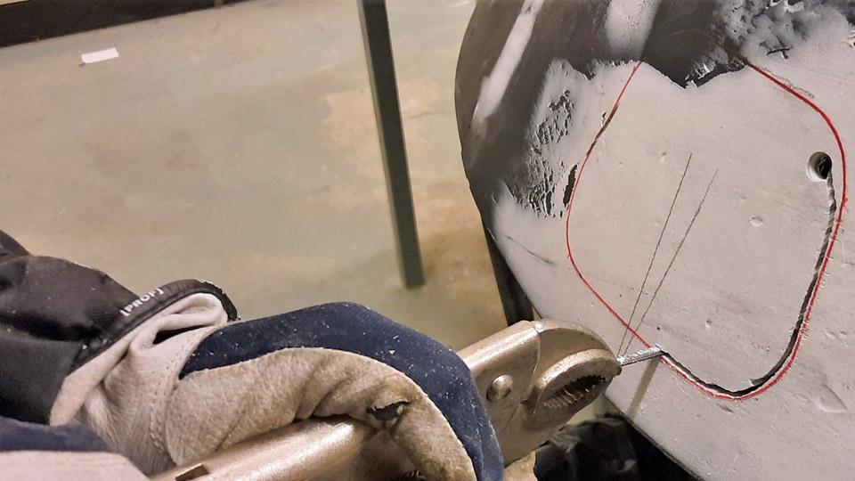
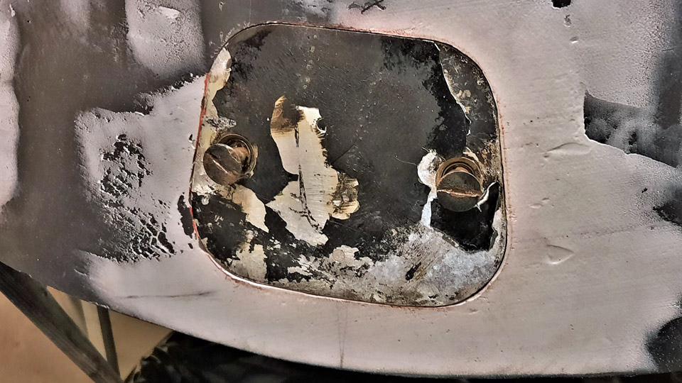
Photos by Reijo Siirtola The repair of the Caravelle III (DAF) nose radome damage was started by making an opening for the cover for the attachment bolt in the damage point, which was laminated over. An opening was sawn according to the measurements of the cover with a keyhole saw, after which a rabbet was laminated along the edges of the opening, against which the cover will be pressed and locked to the frame of the attachment bolt. Simultaneously the straightening of the damage to the nose pressure bulkhead outer circle was started. The crushed bulkhead circle has to be straightened in order to get the radome edge to be pressed tightly against the bulkhead circle and locked in place with three bolts.
Photo by Heikki Kaakinen By the beginning of the summer the starboard wingtip and the starboard horizontal stabilizer damages have to be repaired, so that everything will be ready when the Caravelle III (OH-LEA , ex SE-DAF) ) called “Bluebird” in Finnair colours will be transferred from the Pansio hall in Turku to close proximity of the Turku Airport terminal.
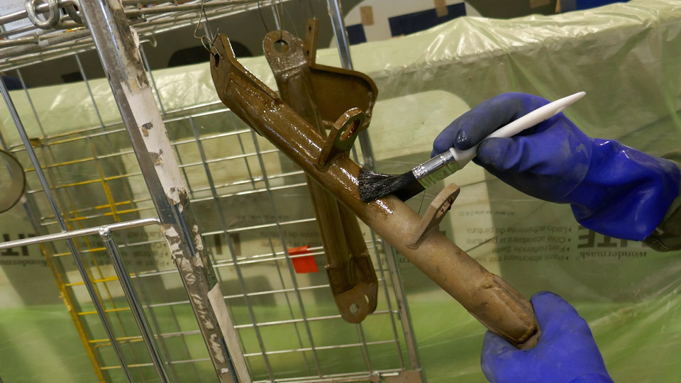
Photos by Juha Veijalainen The surface handling of the parts of the Caravelle towbar, which was brought along with the Caravelle III from Arlanda, is underway. The towbar used by SAS will be restored to the livery of the towbars used by Finnair. The sandblasted parts of the towbar are being painted with the grey Isotrol primer. The surface colour will be “Finnair blue”, apart from the towbar ends, which will be painted with yellow high visibility paint.
Photo by Antti Laukkanen
Photos by Juha Veijalainen
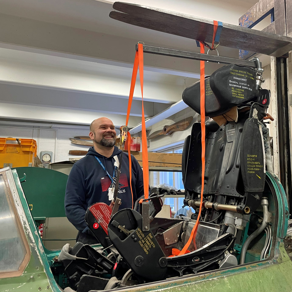
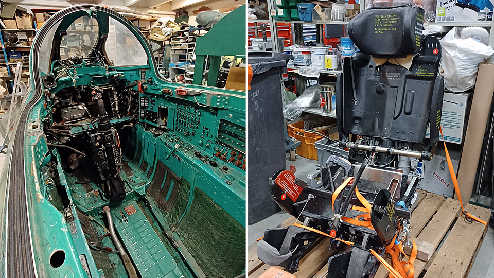
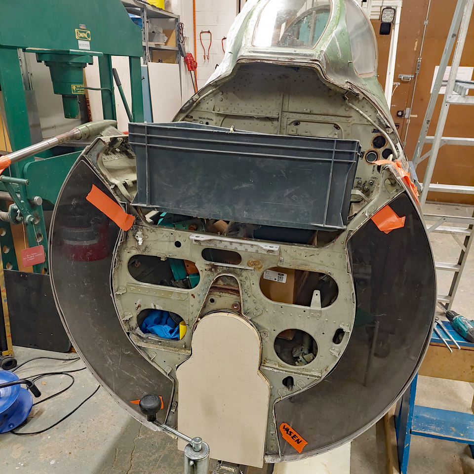
Photo by Osmo Väisänen We finally managed to dislocate the pilot’s seat from the cockpit of the MiG 21 BIS (MG-111), which will be transformed to a cockpit simulator. The dislocation was made possible by a dislocation bar, instructions and a manual received from the Guild of the Karelian Wing. Lots of original wiring still needs to be removed from the cockpit, before we can have access there to install the actual simulator equipment. The covering of the engine air intake duct openings in the cockpit rear and front bulkheads with plexiglass is underway.
Photo by Heikki Kaakinen Work continues with the Caudron C.50 (CA-50) aircraft. The re-covering of the fully restored port elevator with linen fabric was started and the unsatisfactorily tightened patches on lower wings were continued to be replaced with modern Oratex-material. The winter season barely allows any work on the interior of the DC-3 (DO-5) fuselage owned by Aviation Museum Society Finland. Work will continue with the warmer spring weather. Well, we have achieved something; the door between the cockpit and the cargo hold has received a new coat of paint. Translation by Matti Liuskallio. |
|
Avainsanat: aviation history, restoration, MY-14, VL Myrsky, Caudron C.59, CA-50, MiG-21BIS;MG-111 |
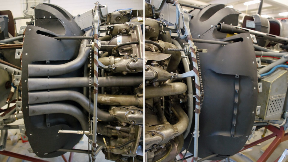
Working on the gills at TikkakoskiMaanantai 17.10.2022 - Reino Myllymäki When the transporting of ace Kyösti ” Kössi ” Karhila’s war trunk from Katajanokka to the Air Force Museum at Tikkakoski was added to the trip to Mikkeli, the opportunity offered itself to go and visit the Museum restoration shop to see and discuss the Myrsky restoration with the assistant conservator Antti Lappalainen. The main switchboard has been under work lately (of which there’s been a blog) and the engine radiator gills. They were, of course, rather an advanced construction because they moved lengthwise with the fuselage, without adding drag when deployed. According to historical documents the idea was taken from the gills of Junkers Ju-88, although in this bomber the gills opened outwards, at least according to photos.
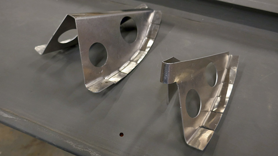
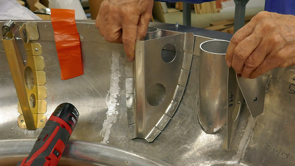
Of the Myrsky gills mainly parts of the gill actuating motor and some bearing housings have remained, in other words much has been done and must be done as neo production. A big entity are the actual gill plates, which superficially seem simple, but are rather complicated entities.
The gill mechanism, that leans on the cowling support frames, works so that the gill motor transforms the rotating movement through an axle and chain to screws, which when rotating move the gills lengthwise on their axles. The gills can be left in any position between their fore and after positions.
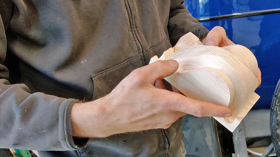
The gills are rather ”interestingly” shaped by the machine guns. In the photo carpenter/artisan Mika Rautasaari holds in his hand a mould or last of a gill that was milled out of wood in the spring. Based on this mould the part of the gill by the machine gun will be made. The final stretch in the restoration of MY-14 is looming on the horizon. Translation: Matti Liuskallio. |
|
Avainsanat: aviation history, restoration, MY-14, VL Myrsky |
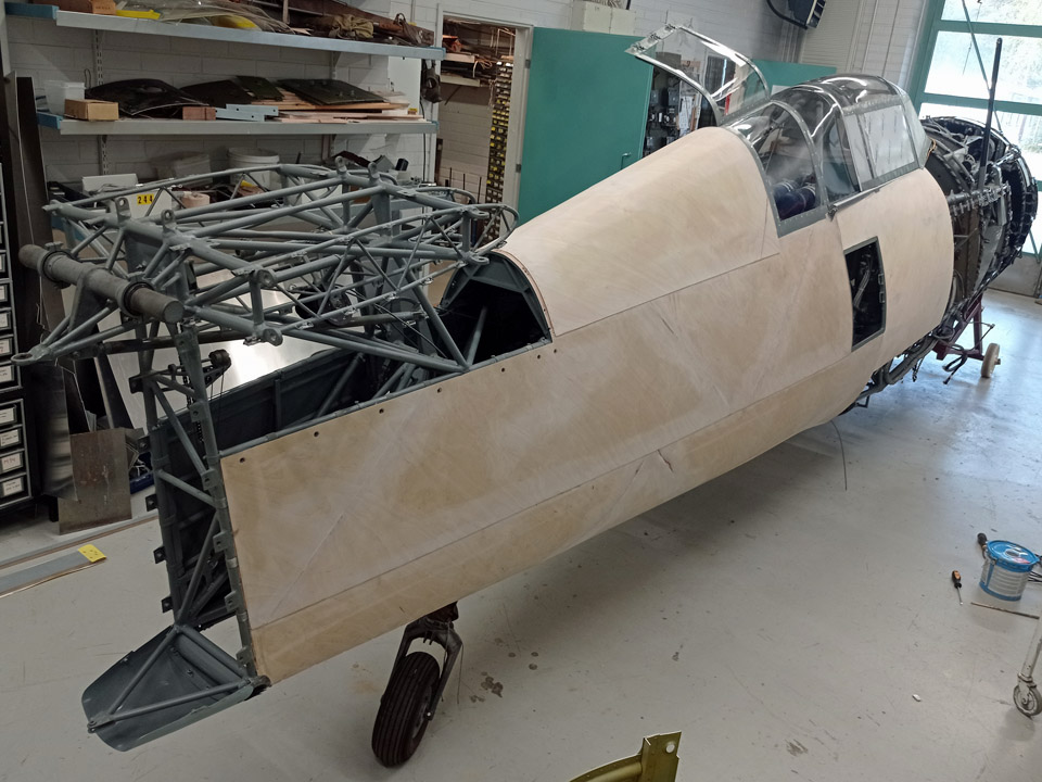
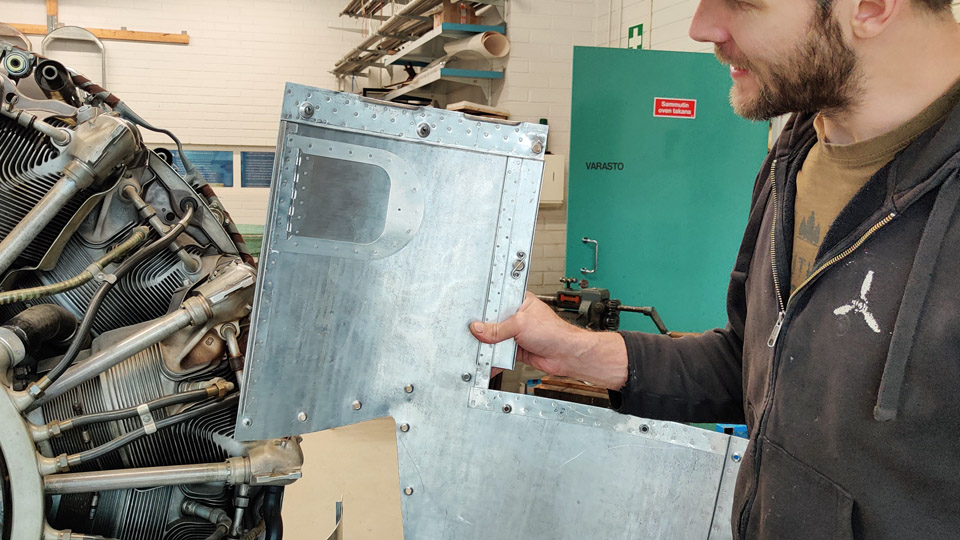
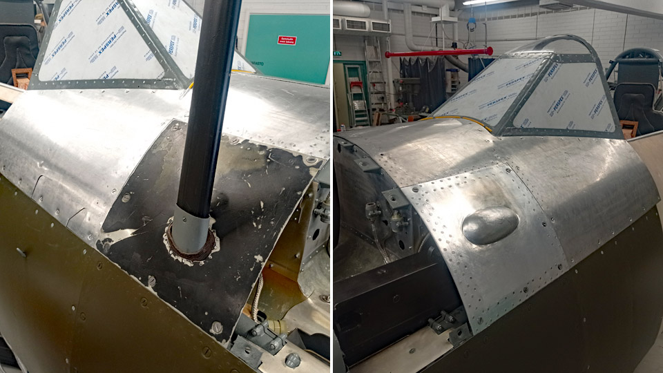
A glance under the cowling at TikkakoskiLauantai 10.9.2022 - Reino Myllymäki The undersigned had a chance – and need, too – to visit Tikkakoski to see how the restoration of MY-14 proceeded there. The work on the aluminium sheets forming the front part of the fuselage of MY-14 to make the opening hatches was nearly finished. Of the original sheets of aluminium there remained only a small piece around the root of the antenna mast. It had been part of MY-5 at its time. MY-5 and MY-6 have proved to differ from the other aircraft of the main production batch, even though they belonged to it.
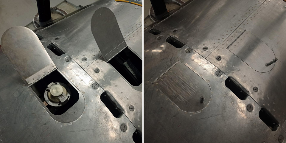
Photos: Finnish Air Force Museum. On the front fuselage sheets there are hatches for entry to the filler caps of the oil-and fuel tanks. There are similar hatches elsewhere, too, but for some reason the width of the hatch for the fuel tank is 10 cm, whereas the width of all other hatches is 11 cm. Because of the 1 cm difference, the parts of the hatch differ from all other hatches. The reason isn’t known, one only wonders….
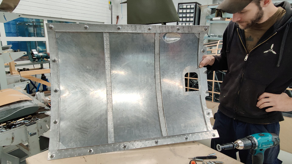
By turning the sheets, more peculiarities appear. The hatches have “happened to be” in a strange position, so that the sheet stiffeners had to be modified so that the side reinforcements, that form the lips of the hatches, could be fitted.
The jigsaw puzzle consisting of pieces of sheet metal is impressive, and the sheets could not have been cut according to plans, but the cutting lines had to be improvised. Such is the situation in restoration, but the state of the affairs has probably been the same when the aircraft were constructed at their time. Some of the braces attach straight to a counter piece in the fuselage, which means that a piece has been cut off from the sheet below. In another place the brace is attached straight to the sheet of aluminium beneath. After a couple of hour’s wondering, the MY-14 stabilizers were packed in my car, where their journey continued to Vantaa. Photos by Reino Myllymäki, unless otherwise indicated. Translation by Matti Liuskallio. |
|
Avainsanat: aviation history, restoration, MY-14, VL Myrsky |
The fitting of Myrsky's NACA-ring bracket formers and brackets for rivetingTiistai 19.7.2022 - Tuesday Club member In the restoration of VL Myrsky II the construction of the engine cowling or NACA ring front part, which is demanding, has been under work already for a couple of years. The Myrsky engine cowling consists of the engine covering NACA ring’s solid front and rear parts and the openable engine cowlings between them. This blog deals with the installing of the bracket formers to be riveted to the solid front part of the NACA ring. Later in this blog the solid front part of the NACA ring will be called NACA ring for simplicity. The Myrsky’s NACA ring has proved to be very difficult to make, and we have not managed to avoid extra work. This was caused by amongst other things the uncovering of the lost Myrsky major series NACA ring drawings at the end of last year. They differ especially in the upper part from the initial series Myrsky’s NACA ring drawings, according to which we have been building the MY-14 NACA ring. The difference between the drawings was, that in the major series NACA ring the diameter of the upper part of the ring is larger than that of the initial series. Because of this, the NACA ring that we had built had to have its upper part diameter increased, so that it would correspond to the shape of the major series shape of MY-14. The enlargement was possible by forging the upper part of the aluminium ring to the measurements of the major series. There are 14 bracket formers in the NACA ring altogether. Of those, ten are situated in the part of the NACA ring, which equates the rotation block. Four bracket formers are situated aside from the rotation block in the expanding upper part of the NACA ring. The opening of the air horn and the flame tubes of the four machine guns are situated in this area.
At the same time a jig was made out of a steel plate, to assist in focusing the bracket formers to their places. With the aid of a set up jig, which was made out of steel plates and locked in the “central hub” of the assembly table, two bracket formers can be positioned into place. After that the jig is moved forward to position and install the next bracket formers. The positioned bracket formers were fastened to the NACA ring with a couple of small bolts. The final fastening will be done by riveting.
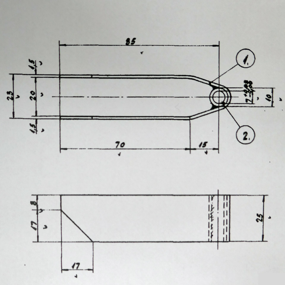
When the chromated 10 bracket formers had been installed, the actual brackets were installed at their tips, with which the NACA ring is locked with connection pieces to the eyes of the valve housing of the engine. The bracket on the former is a prong-like piece, bent from 1 mm steel plate, which has a welded socket for the fastening bolt at the end.
The brackets are installed at the end of the formers at an angle of 7.5 degrees. So they will meet the valve housing eyes to fasten the NACA ring to the engine. The brackets of the formers and the eyes of the valve housing are locked to each other with connecting pieces. The connecting pieces are fastened with bolts to sockets at the end of the former and with two bolts to the holes of the eyes in the valve housing.
When all ten chromated bracket formers with their brackets had been installed in place, the shaping work of the four bracket formers and their brackets to be installed on the upper part of the NACA ring was started. The bracket formers by the outer flame tubes are distinctly shaped more open-angled, compared with the other V-shaped bracket formers, to enable the flame tubes inside them. The bracket formers that are fixed on either side of the air horn differ from the other bracket formers in shape. In a way they are only half-sized compared with the other V-shaped formers.
First the open-angled bracket formers at the flame tubes were shaped to be installed. They were fastened tentatively in place with the aid of a jig, made especially for these two brackets. After this the shaping of the prongs, attached at the end of the bracket formers with sockets, so that they could be shaped into the form of more open bracket formers. The position of these brackets differs from the other bracket formers so that the bracket is right at the top of the bracket former. The installing of the bracket formers of the NACA ring upper part are still under work. Photos: Lassi Karivalo Translation: Matti Liuskallio. |
|
Avainsanat: aviation history, restoration, Tuesday Club, MY-14, VL Myrsky |
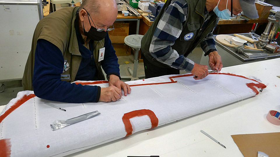
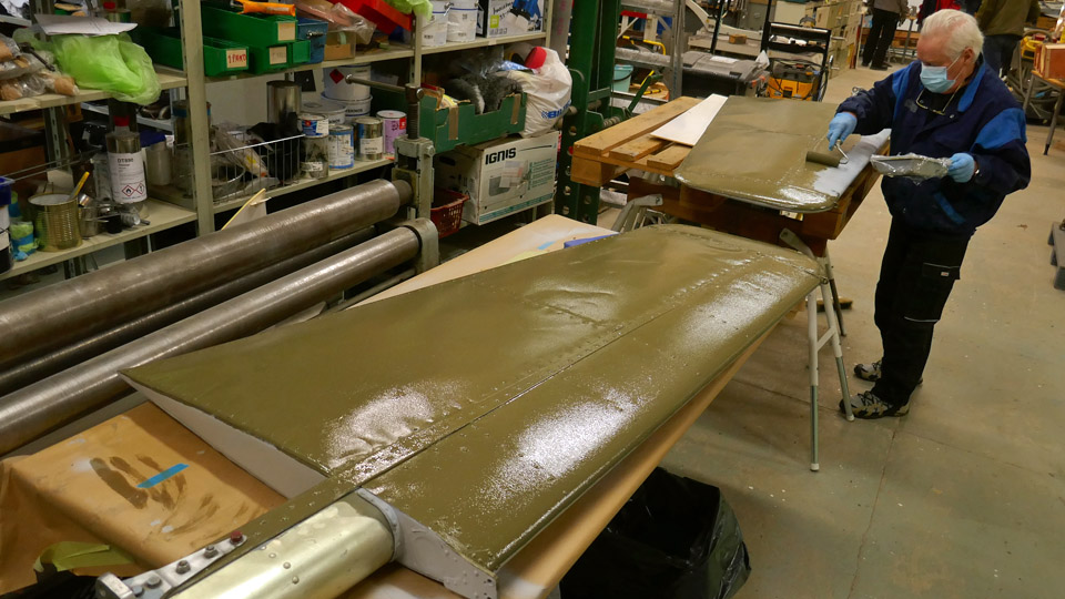
The Myrsky elevators? primingKeskiviikko 6.7.2022 - Tuesday Club member The VL Myrsky II (MY-14) elevators’ coating, which had started in April was finished at the beginning of May. As coating fabric, a 165 g/m2 linen fabric was used.
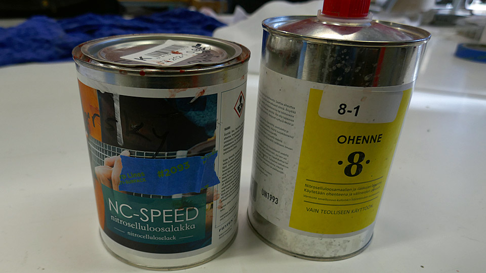
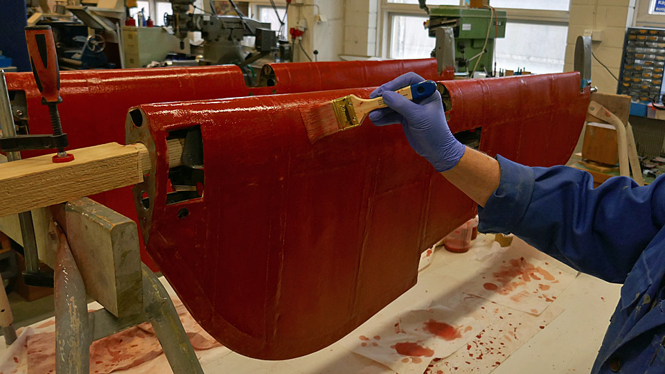
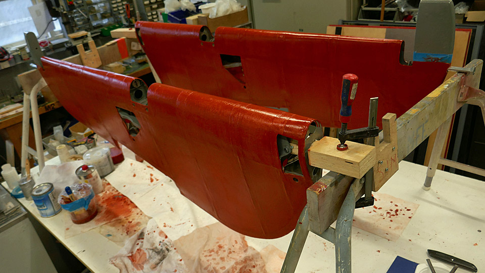
After the elevators were finished, the fabric was tightened to resemble a drum top with NC-SPEED nitro cellulose varnish. The varnish was dyed red with iron oxide. The tightening of the fabric was done phase by phase. It began with 50% thinned varnish. Thinner 8 was used for the purpose. From that we continued through 75% varnish to a full 100% varnish. Unthinned varnish was applied twice to the fabric cover of the elevators.After the elevators were finished, the fabric was tightened to resemble a drum top with NC-SPEED nitro cellulose varnish. The varnish was dyed red with iron oxide. The tightening of the fabric was done phase by phase. It began with 50% thinned varnish. Thinner 8 was used for the purpose. From that we continued through 75% varnish to a full 100% varnish. Unthinned varnish was applied twice to the fabric cover of the elevators.
Between the times of doping, the fabric surfaces were sanded smooth. After every application of varnish, the fabric tightened more. After four layers of varnish the fabric of the elevators had tightened to the wanted drum top level.
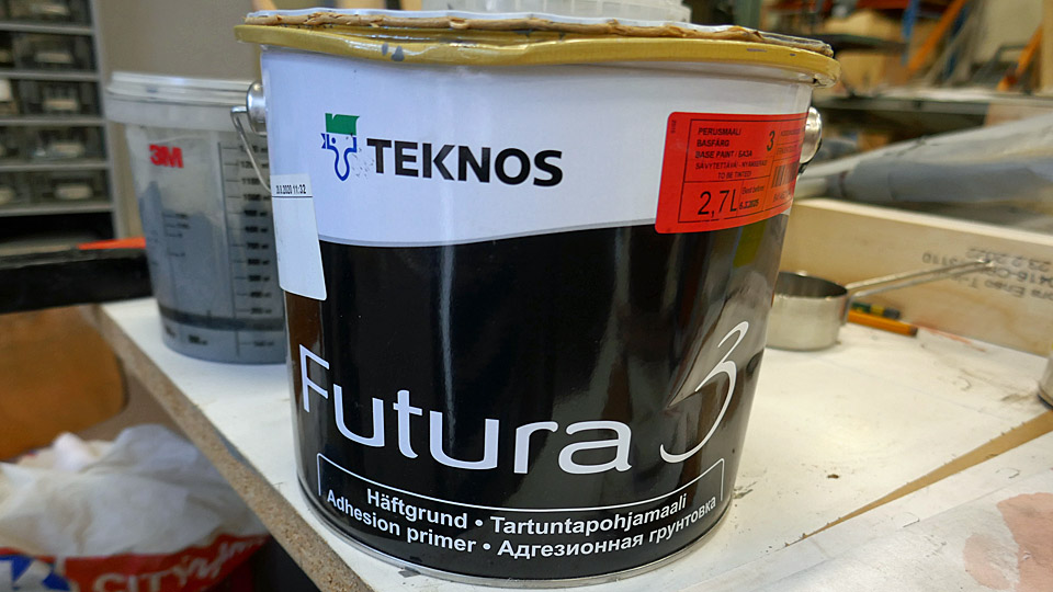
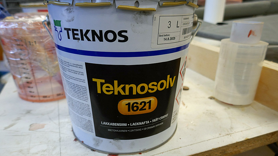
After tightening of the covering fabric, it was time to prime the elevators. TEKNOS Futura3 primer was chosen, and Teknosolv 1621 white spirit as thinner.
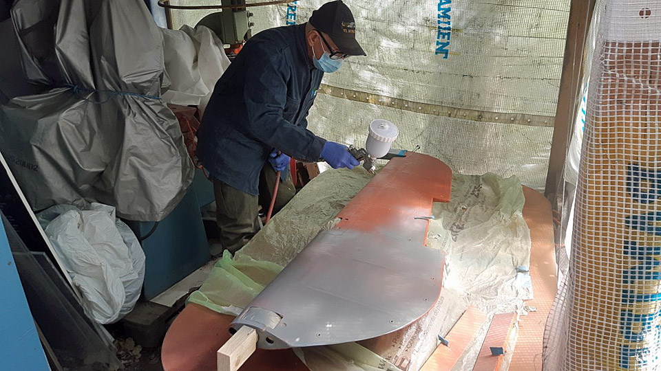
The priming was done by spraying, using the Futura 3 which was thinned to 75%. Before spraying, the openings in the elevators were covered to prevent the paint to get inside the elevators.
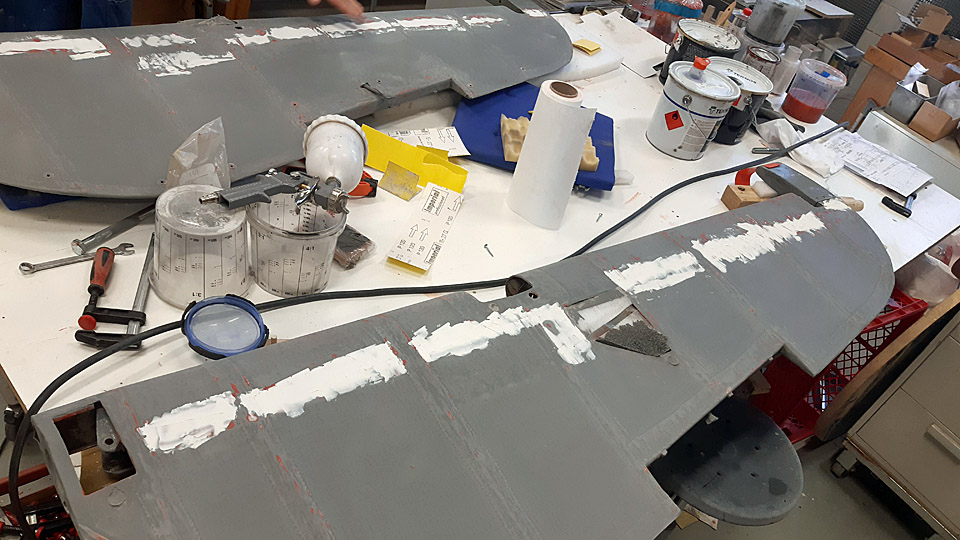
After spraying, the surfaces were sanded manually. At the same time, it was noticed that there was a slight depression on the trailing edge side of the elevator, along the whole length of it. Filler was applied to this area. After the filler had dried, the area was sanded to the form of the curvature of the elevator profile.
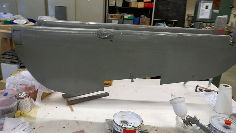
The second layer of the primer was also done with 75% Futura 3 primer. After spraying the surfaces of the fabric were sanded smooth. Special care was taken to the serrated edges of the protective strips on the sewn seams, so that the serrated edges could be sanded, so that they no longer feel like uneven spots on the surface of the fabric.
The elevators of the Myrsky have now been primed twice. We are debating that a possible third layer of primer could be sprayed on the surface of the elevators. Photos: Lassi Karivalo Translation: Matti Liusvaara. |
|
Avainsanat: aviation history, restoration, Tuesday Club, MY-14, VL Myrsky |
Tuesday Club started its spring season with full capacityTiistai 1.3.2022 - Tuesday Club member Suomeksi The Tuesday Club was not able to start its spring season in January because the amount of people allowed to work in the restoration workshop of the Finnish Aviation Museum was still limited due to the Covid-19 pandemic. Only the restoration work on the Myrsky MY-14 could be continued in January. Only half a dozen Tuesday Club members could work at a time, wearing masks. In the beginning of this year the Myrsky project has concentrated on the NACA-ring and the port wing landing gear doors, as well as finishing the Myrsky demo-wing before the Myrsky restoration exhibition will be opened.
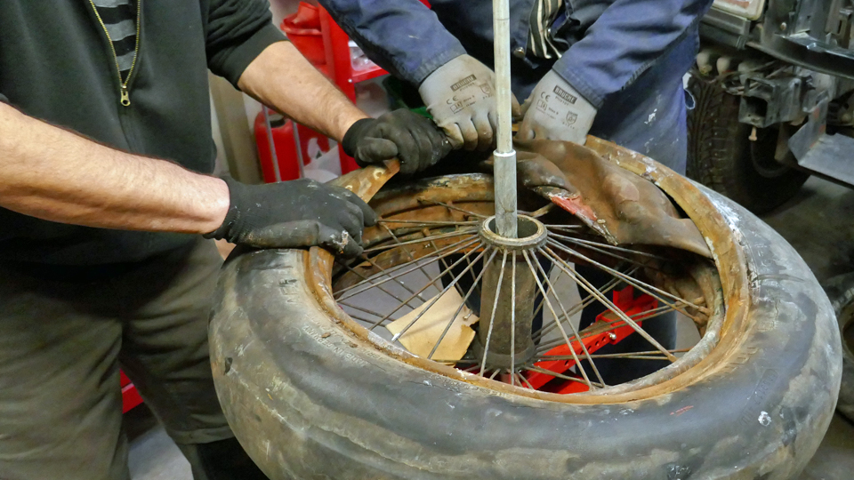
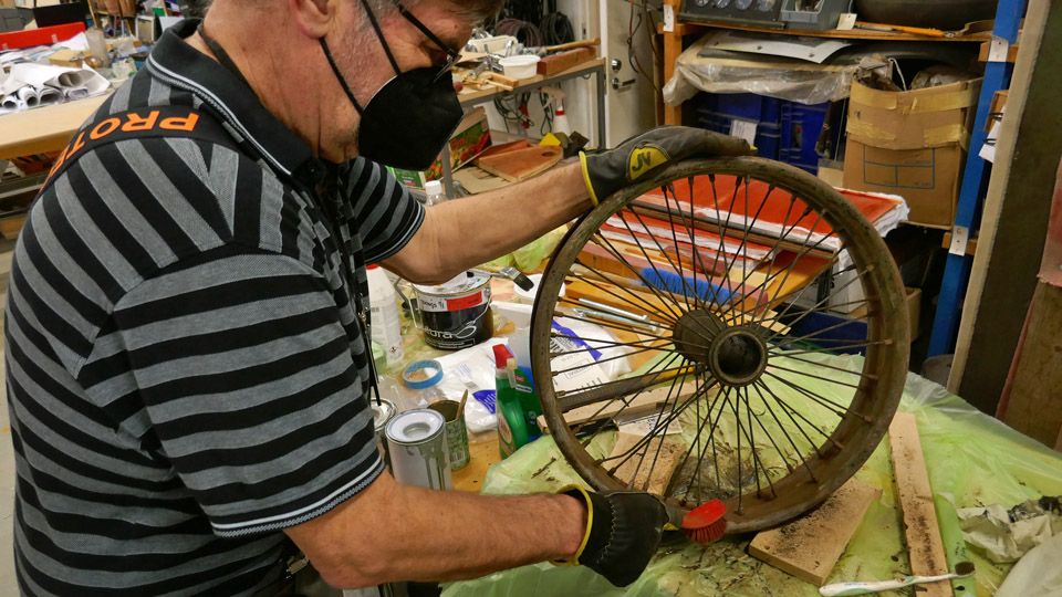
Along with the Myrsky restoration work, a couple of Tuesday Club members have been working to finish the painting of the Mil Mi-8P (HS-6) helicopter tail boom stabilizers and to take the large parts of the Super Caravelle towbar to be sandblasted. The tyres of two 1920s aircraft wheels have also been dismantled so that the wheels can be repaired. These wheels have been received from the Finnish Air Force Museum to be assembled on the Caudron C.50 (CA-50) aircraft.
As the national Covid-19 restrictions have been lifted due to the decreased health risks caused by the pandemic, it was agreed with the Finnish Aviation Museum that the number of people working in the restoration workshop can be increased. This enables us to launch other Tuesday Club activities in addition to the Myrsky work. On February 23rd we continued from where we stopped before Christmas, particularly with the Caudron C.59 conservation and the Super Caravelle towbar restoration. We still work in two groups of 10 Club members, one group on Tuesdays and the other on Wednesdays. The Myrsky team, with less than 10 members, is working on Tuesdays, Wednesdays and Thursdays.
The coming weeks will be spent in cleaning the parts which were dismantled from the Caudron’s fuselage, and after that the parts will be painted. Two landing gear wheels were received from the Finnish Air Force Museum for the Caudron. The wheels and spokes are cleaned from dirt, grease and rust. Mechanical and chemical methods are applied.
The Caravelle towbar has been dismantled and all dismantled parts have been cleaned of rust, either with phosphoric acid or by sandblasting, and the painting work can be started. Before painting, the sandblasted parts were washed to remove the sand dust, which remained on the surface. Then the parts were carefully dried, using compressed air. Some parts have already been painted with clear Isotrol varnish which will prevent rust. Photos: Lassi Karivalo Translation: Erja Reinikainen. |
|
Avainsanat: aviation history, restoration, VL Myrsky, MY-14, Caudron C.59, CA-50, Mil Mi-8P, HS-6, Super Caravelle |
Situation update from TikkakoskiTorstai 24.2.2022 - Reino Myllymäki A visit to Tikkakoski on February 11th made it possible to write one situation update, that was published on February 20th, 2022. But on February16th the restoration group at Tikkakoski sent more updates, mainly pictures.
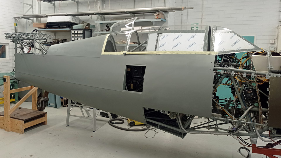
The covering sheets around the wind screen are nearing to being completed. Mind you, of the original sheets only one survived, around the root of the antenna. All the others are made of the blanks, constructed by Antero Flander. Riveting was a huge job, 2500 flush rivets! Now the first covering sheets have been primed and surface painted, although the olive green will yet be revived and the final lines between the colours will be repainted with the camouflage painting.
The tail fairings have also received priming and surface coats of paint. Fitting them in place can start now, as the stabilizers are at Tikkakoski for test fitting.
The fire plate has been painted matt black and refitted. The disassembled exhaust pipes, too, have been refitted on February 11th.
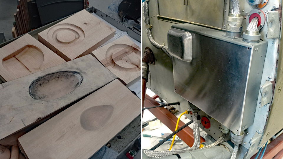
The front firewall switch case has been fitted with a cover, on which a” bulge “ was made by forging against a wood last. Other wood lasts have been made for forging, partly with CNC-milling, partly by hand crafting. The “bulges” by the machine gun breech block solenoids that look small in photos, are in fact quite large. They, too, have been made by forging against wood lasts.
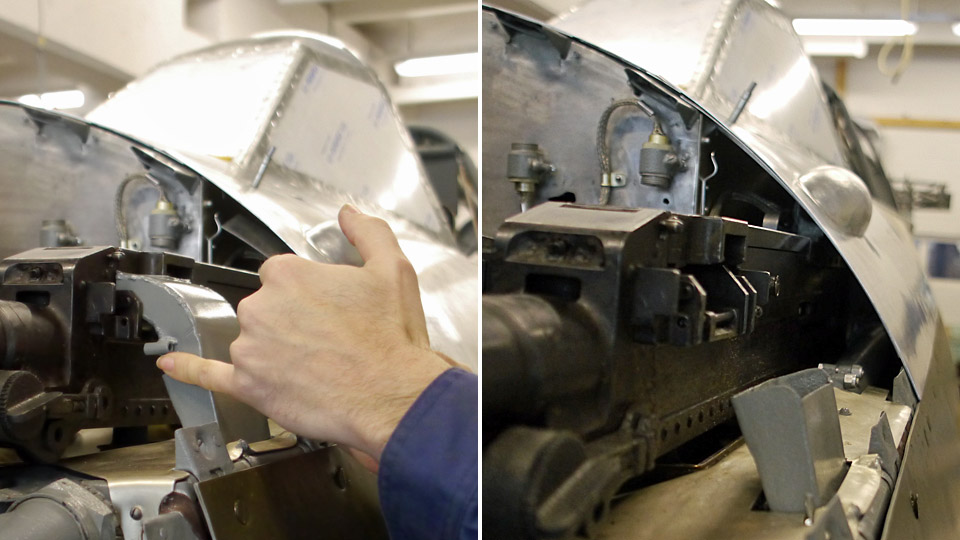
The “bulge sheets” by the outer machine guns have been constructed in such a manner that the breech cover can be opened and closed without taking the whole sheet off. On top of that, it was observed that the cartridge chutes of the outer and inner machine guns differ from each other in the extent of material thickness. They were probably designed by different draughtsmen.
Photos: The Air Force Museum, unless otherwise mentioned. |
|
Avainsanat: aviation history, restoration, MY-14, VL Myrsky |
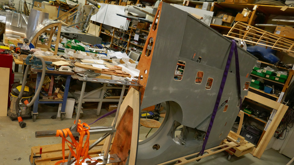
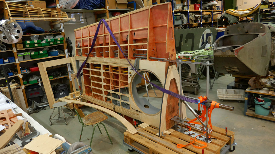
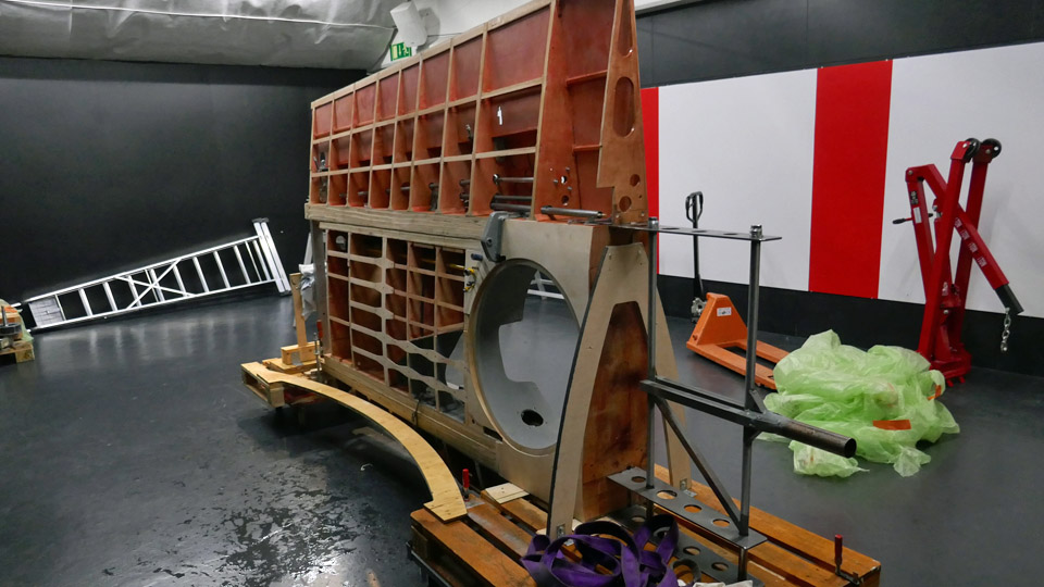
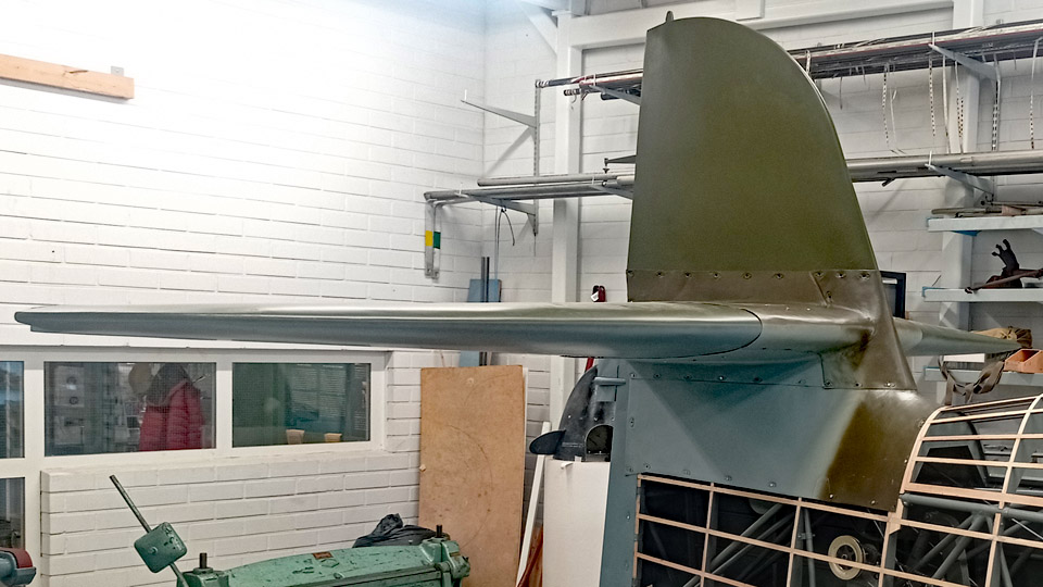
Myrsky's demo wing was moved to mid hall of Finnish Aviation MuseumTiistai 22.2.2022 - Tuesday Club member When the underside of the demo-wing, built in the VL Myrsky II (MY-14) restoration project, had been painted with Futura 3 adhesive primer, it was ready to be moved from the restoration workshop of the Finnish Aviation Museum into the museum’s mid hall. An exhibition about the VL Myrsky II restoration project will be built in the mid hall. The demo wing will be used in the exhibition to show the museum visitors what the wood-structured wing and the equipment were like in the Finnish WWII VL Myrsky fighter. All the equipment of the Myrsky’s wing have been assembled into the demo wing, including landing gear, operating mechanisms of the ailerons and the hanger for the auxiliary fuel tank / bomb. To allow a better view of the wing structure, the upper side of the wing has not been covered with plywood.
The demo wing includes a 2,5-metre section of the starboard wing and a one-metre root part of the port wing. The demo wing was used for testing how to build the Myrsky wing’s root part before starting to build the actual wings for the Myrsky MY-14. Now the demo wing will be used as a showpiece.
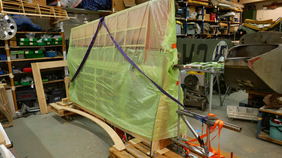
For moving the demo wing into the exhibition, pallets with wheels were fastened at both ends of the wing, which weighs nearly two hundred kilos. The demo wing was supported on racks made of steel and plywood, fastened on the pallets. The wing was locked into a vertical position with the leading edge downwards.
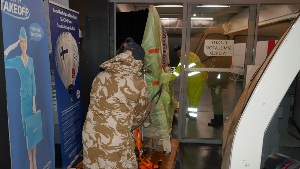
Having the wing in this position was the only way to manoeuvre the wing through the flight simulator room in the Aviation Museum’s mid hall and into the space reserved for the exhibition in the mid hall. Even this way the wing had to be wriggled through the hall inch by inch.
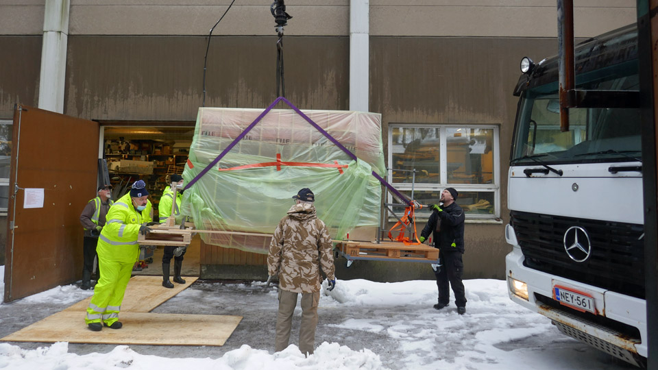
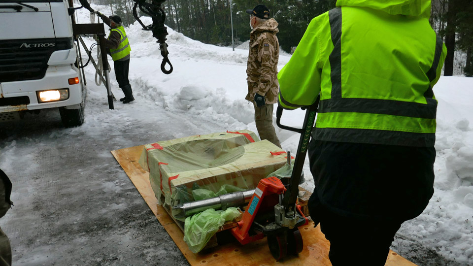
The wing was moved from the museum’s restoration workshop to the mid hall’s outer door on a lorry with a hoist. The transfer took place on a very rainy day, so the wing was protected from the rain by wrapping it in plastic.
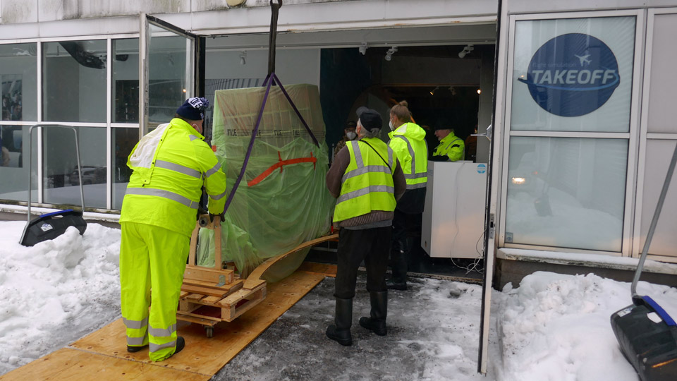
The wing package was pushed out of the restoration workshop on the pallets with wheels, then the hoist straps were fastened. The wing was lifted, using the hoist, and moved onto the bed of the lorry. The lorry transported the demo wing to the mid hall’s outer door. There the wing was lowered in front of the door with the hoist, then it was pushed on the pallets through the door and into the simulator room in the mid hall. The one-metre section of the port wing was also brought to the mid hall on the same lorry.
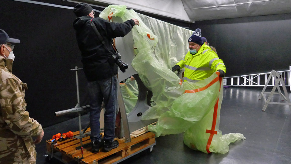
In the simulator room the four-metre demo wing on its pallets was manoeuvred between the simulators until it was at a right angle facing the doorway to the mid hall exhibition area. The demo wing was gently pushed into the space which is reserved for the Myrsky exhibition. It was a close call, because there was only an inch between the pallets and the door frame. When the demo wing had reached its destination, the rain protecting plastic could be removed.
Now the demo wing will be prepared for exhibition. First the pallets will be removed, then the starboard and port side wing halves will be joined, and the landing gear will be assembled into the starboard wing. There will be also a Myrsky’s rear fuselage in the exhibition, with the wooden vertical and horizontal stabilizers, which were built in the Myrsky MY-14 restoration project, and the original metal elevators will be assembled, too. In the Myrsky restoration project the Aviation Museum Society’s Tuesday Club has concentrated, among other things, on the wings, tail, landing gear, oil cooler and engine cowlings. The Finnish Air Force Museum has been working on the fuselage restoration. Hopefully the MY-14 restoration will be completed next year. Then the genuine Finnish WWII Myrsky fighter would be on display for the public.
The VL Myrsky II restoration project exhibition is open between 5.3. – 31.5.2022 at the Finnish Aviation Museum during its normal opening hours. The exhibition is in the mid hall, used for changing exhibitions, and a museum ticket is needed. The ticket prices are: adults 12 €, reduced groups 6 €, children below 7 years € eur and Museum Card 0 €.
I warmly recommend a visit at the Myrsky exhibition which will open in March. There you will learn about the restoration work of Myrsky MY-14 and about the history of the Myrsky fighter, which was the only WWII fighter of the State Aircraft Factory to reach series production phase. Photos: Lassi Karivalo. Translation: Erja Reinikainen |
|
Avainsanat: aviation history, restoration, VL Myrsky, MY-14, MY-5 |
The stabilizers to Tkkakoski, wheel to VantaaSunnuntai 20.2.2022 - Reino Myllymäki The undersigned had a chance to visit the Air Force Museum at Tikkakoski on Friday Feb.11th 2022. As earlier, the trip had many purposes. The day before yesterday I went to photograph the Sasky aircraft at the Mänttä agency and on Friday the main purpose was to scan the photo albums of Paavo Kahla and Kurt Södergård for the coming Paavo Kahla book.
But since I was at Tikkakoski, I went to see the Myrsky - II project situation. Now I had reason more than usual, because in the boot of the car came the MY-14 stabilizers from Vantaa to Tikkakoski for the fitting of the fairings.
The stabilizers had a coat of paint on the surface, only the black camouflage colour on top of the olive green was missing. The paintwork on the plywood surfaces of the stabilizers seemed very good compared to the original parts, as can be seen in the photos.
Also the fire plate had been painted at Tikkakoski. The matt black doesn’t really show in any photos, and we don’t know for sure, whether the Myrsky aircraft were painted like this, although this is strongly supported by the painting of the VL Humu’s respective parts. Photos: Reino Myllymäki Translation: Matti Liuskallio |
|
Avainsanat: aviation history, restoration, MY-14, VL Myrsky |
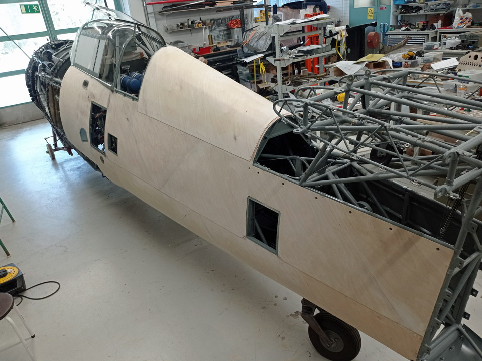
MY-14 fuselage covering with plywood is progressing againSunnuntai 12.12.2021 - Reino Myllymäki According to the photo update from the Air Force Museum from today, it’s plain to see that the covering of the fuselage of MY-14 with plywood is progressing, as well as the making of the aluminium hatches in the covering.
The front fuselage cover hatches have been made of Antero Flander’s blanks, which have been cut to measurements and riveted together. Easier said than done, because there are myriads of 2,6 mm rivets, double the amount compared to the Brewster, so they say. And they aren’t even load carrying parts.
The covering sheets themselves are of 1mm thick aluminium thin sheet. The pins of the Dzus-locks on one of the cover sheets are original VL produce, apart from them the parts are neo products.
The port side plywood covering is about to be finished. Photos: Reino Myllymäki Translation: Matti Liuskallio. |
|
Avainsanat: aviation history, restoration, MY-14, VL Myrsky |
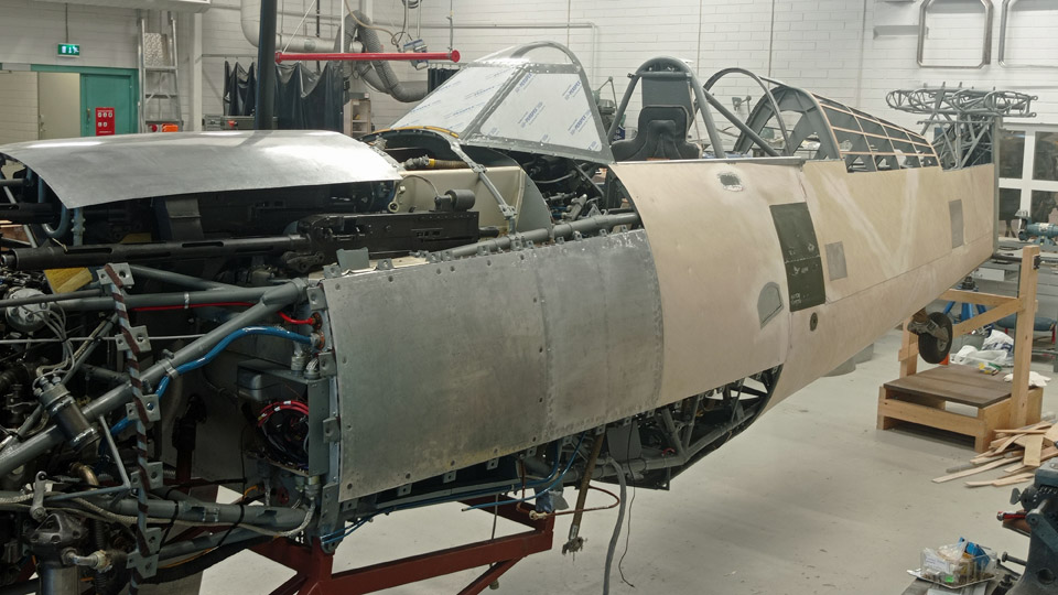
Filler ring and supporting ring of Myrsky?s NACA-ringMaanantai 25.10.2021 - Tuesday Club member The NACA-ring of the VL Myrsky II is complicated to build. Fortunately the most difficult phases of work have already been completed at the Tuesday Club when building the ring for the Myrsky MY-14 engine, which is under restoration. When the NACA-ring and its parts have been chromated and the fastener consoles, among others, have been fastened on the inner surface of the ring, the NACA-ring can be test assembled on the Pratt & Whitney R-1830 engine, which is available at the Finnish Aviation Museum. It is rather fortunate that this engine is on display at the Aviation Museum and there is no need to travel for the test assembly all the way to Tikkakoski, where the Pratt & Whitney engine has already been assembled on the MY-14 fuselage, under restoration at the Finnish Air Force Museum. The engine, which is available at the Finnish Aviation Museum, has been on a DC-3 but it suits well for the test assembling of the Myrsky’s NACA-ring.
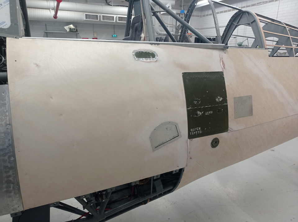
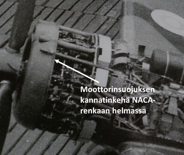
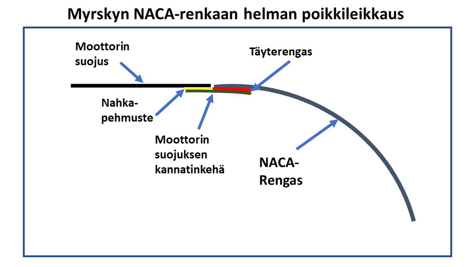
The Tuesday Club team has been working lately on the filler batten ring (täyterengas), which will be fastened on the edge of the NACA-ring (NACA-rengas), as well as the supporting ring (moottorin suojuksen kannatinkehä) for the engine fairing. The supporting ring is fastened on the filler ring and its edge extends 30 mm outside the NACA-ring’s edge. The supporting ring forms a base outside the NACA-ring’s hem for the edge of the engine fairing. The supporting ring is covered with leather (nahkapehmuste) to absorb the resonance between two aluminium surfaces, which is caused by the engine.
First the filler ring, a 40 mm wide ring cut from 2,5 mm thick aluminium sheet, was fastened on the edge of the NACA-ring. The filler ring was shaped to match the curvature of the NACA-ring’s edge and preliminarily fastened on it with clamps. Then the filler ring was fastened with small bolts. When the ring was firmly in place, the bolts were replaced with flathead machine screws so that the surface of the filler ring is smooth when the supporting ring is assembled on it. Eventually both the filler ring and the supporting ring will be riveted on the NACA-ring.
85 mm wide strips were cut from 1,5 mm thick aluminium plate for constructing the supporting ring. One edge of each strip was bent to form a small gutter. Then the strips were shaped against the filler ring to match the curved shape of the NACA-ring. In the shaping process the supporting ring is also pressed tightly against the filler ring surface. When this had been achieved, holes were drilled through the supporting ring and the filler ring, and the supporting ring was fastened on the filler ring using small bolts.
The filler ring and supporting ring had to be made also where the machine gun barrels penetrate the NACA-ring. This was not easy because the machine gun barrels form “bumps” on the edge of the NACA-ring. This means that the filler ring and the supporting ring had to be shaped to match the gun barrel “bumps”. Several rounds of modifications had to be made before the filler ring and the supporting ring fitted nicely into place at the barrel “bumps”. During the modification process it had to be checked that the edge of the supporting ring extended exactly 30 mm outside the hem of the NACA-ring.
When the supporting ring had been preliminarily fastened, a line of holes was drilled through the ring and the filler ring under it for the future riveting work. Crosshead bolts were placed temporarily into the rivet holes. Now it could also be checked how the air intake duct of the air horn fits against the supporting ring between the machine gun barrels. Photos: Lassi Karivalo Translation: Erja Reinikainen |
|
Avainsanat: aviation history, restoration, VL Myrsky, MY-14 |
Ilmailumuseot.fi - Aviationmuseums.fi


 Photos: Reino Myllymäki