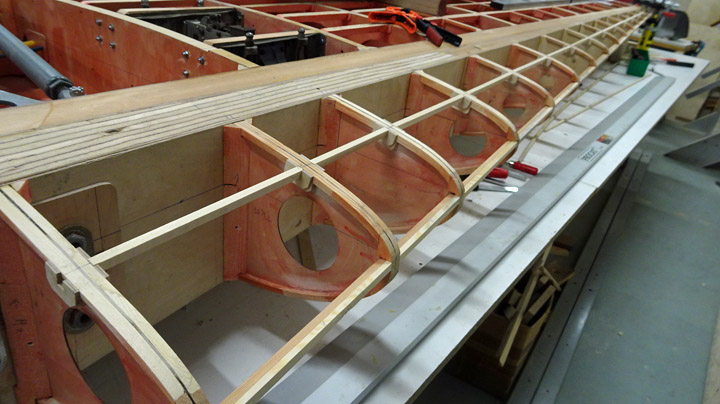
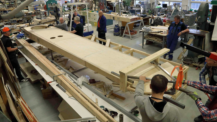
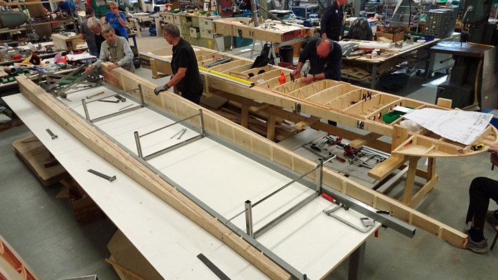
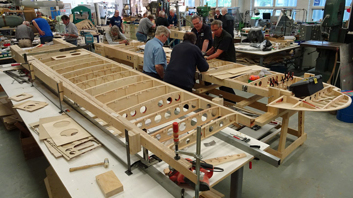
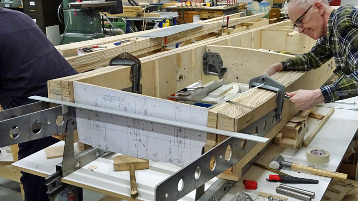
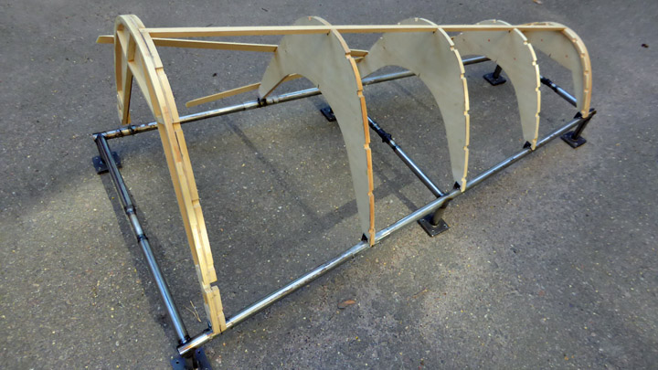
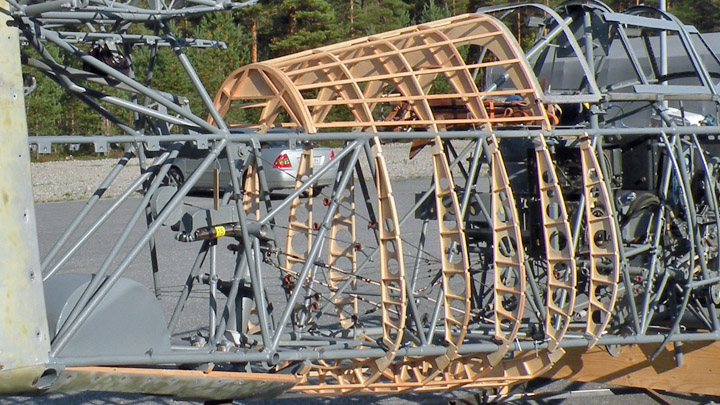
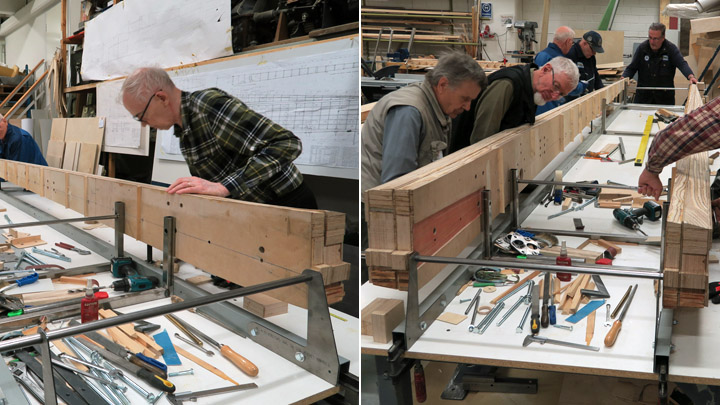
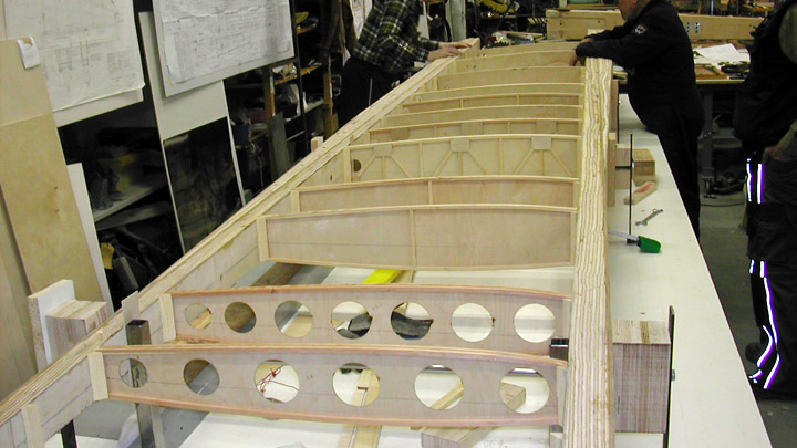
Leading edge of Myrsky wing is assembledKeskiviikko 20.2.2019 - Member of Tuesday Club The Tuesday Club team has been working on the restoration of VL Myrsky’s wings. The work has progressed to the phase when the ribs on the leading edge of the wing can be installed. Previously the ribs have been prepared for the assembly and the tube for the electrical cable of the navigation light has been fastened on the front spar.
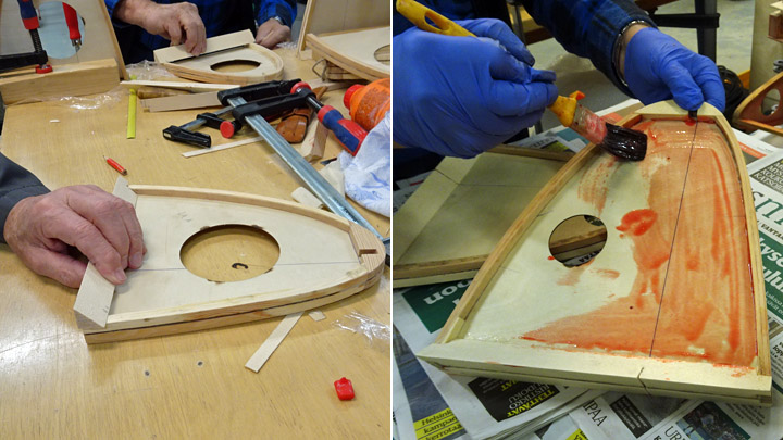
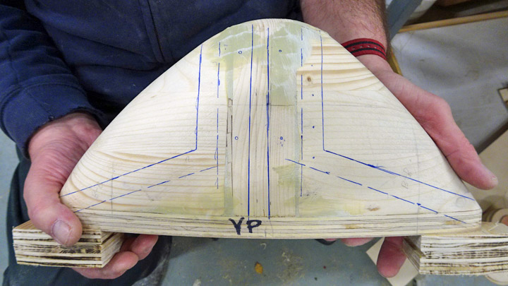
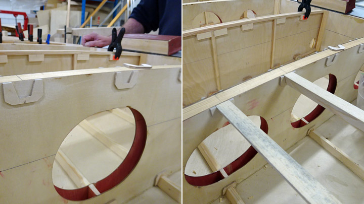
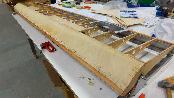
The ribs for the leading edge of Myrsky’s wings were made about a year ago. Triangular wooden battens were fastened on the root of each rib so that they can be glued onto the front spar. This arrangement makes the gluing surface wider on the rib root. Before gluing the ribs into place their sides were protected against humidity using polyurethane varnish, tinted red.
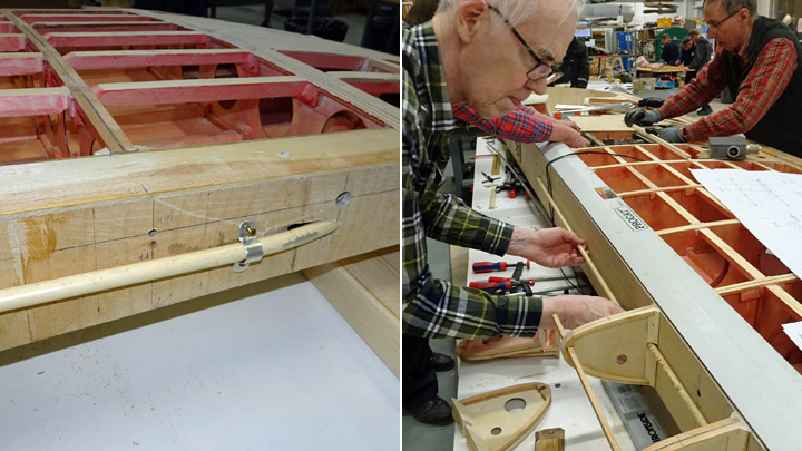
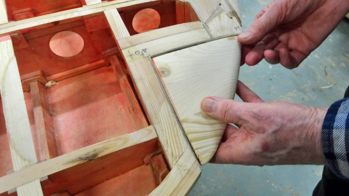
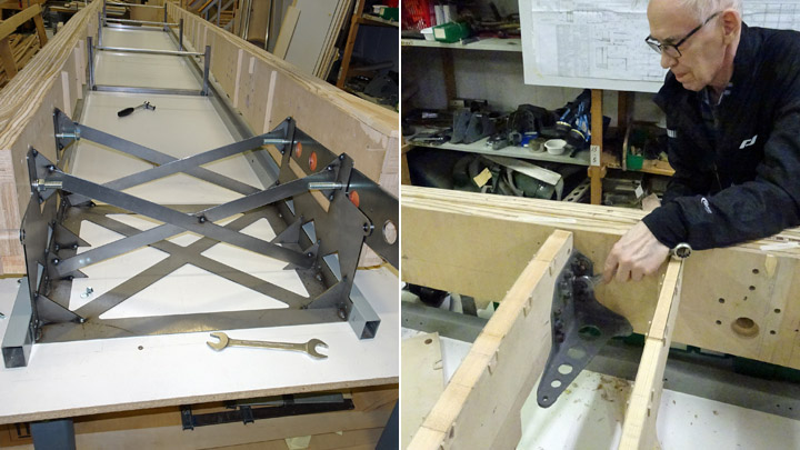
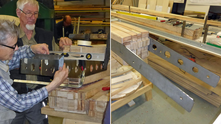
The aluminum tube for the electrical cable of the navigation light on the wingtip was installed before the ribs were installed. The aluminum tube was fastened in the middle of the front spar side facing the leading edge. Aluminum clips were used for fastening the tube on the spar. A notch for the tube had to be carved on the root of each rib before the ribs could be glued onto the front spar.
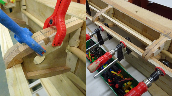
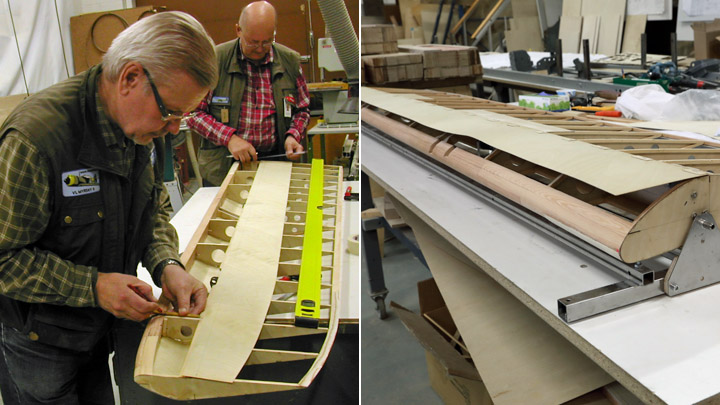
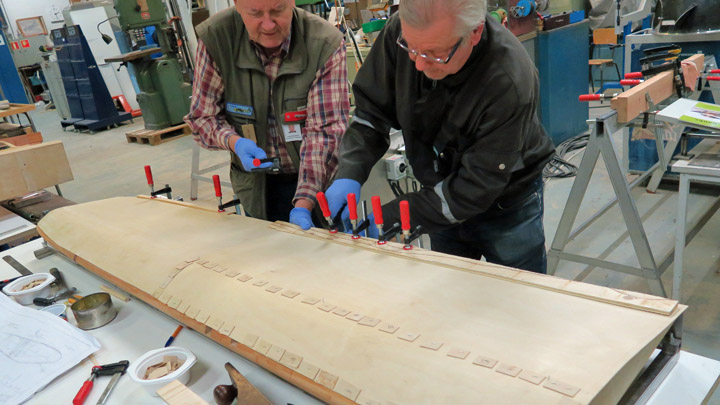
It is important that all the ribs are glued onto the front spar so that their tips are fully in line. If they are not, this will cause problems when covering the leading edge with plywood. A long metal bubble level was the perfect tool for making sure that the rib tips are in line.
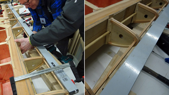
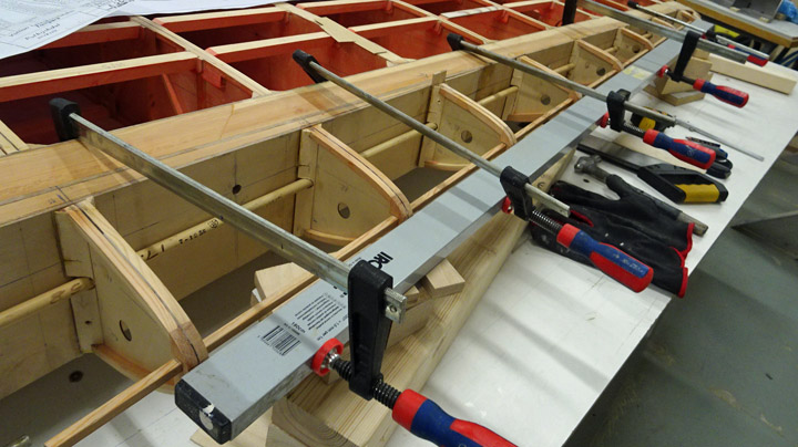
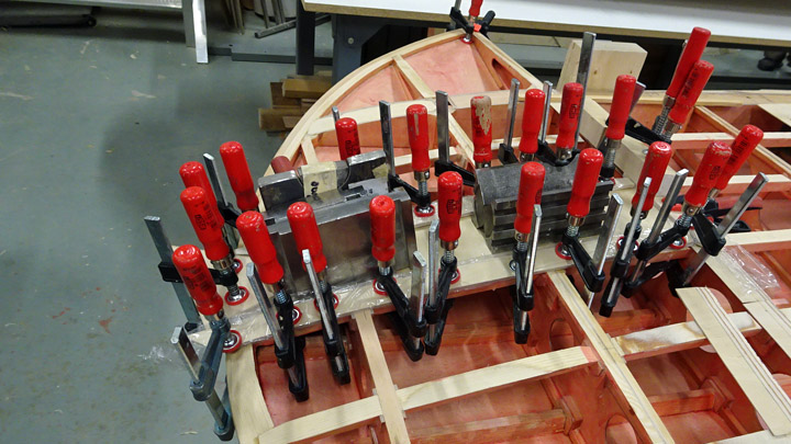
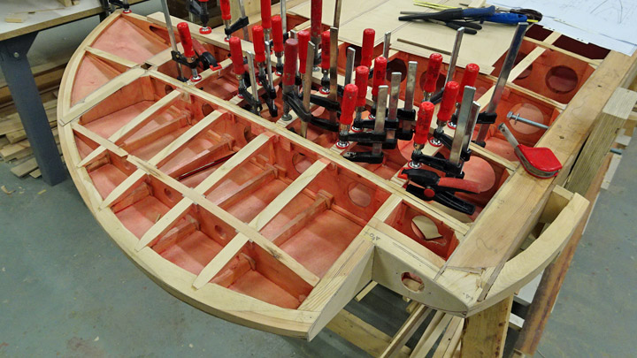
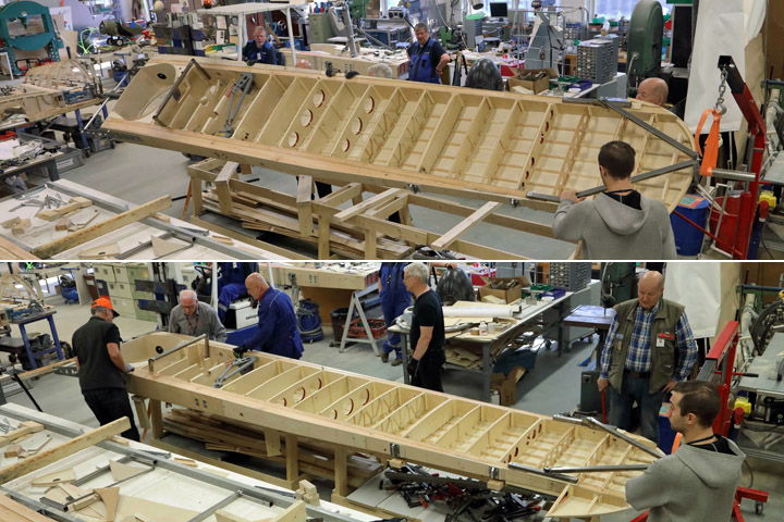
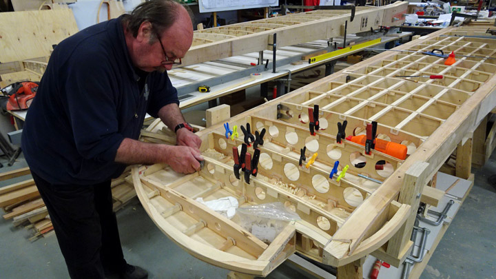
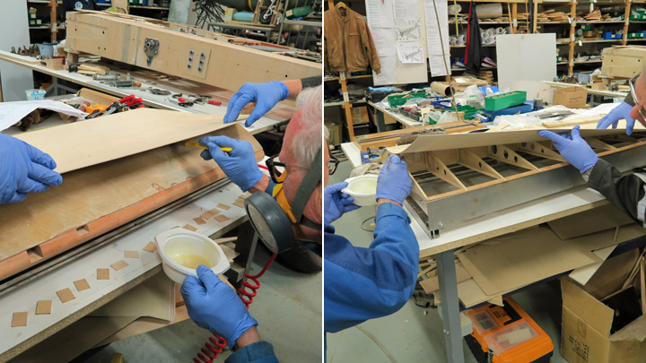
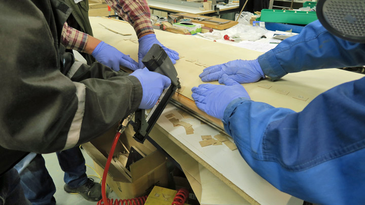
The level showed that the ribs had slightly different lengths, a couple of millimeters. To compensate the error, thin strips of plywood were glued on the root of the shorter ribs. Several ribs had to be modified to make them slightly longer so that the tips met the level. When all the rib tips were in the correct position, a thin connecting wooden batten (8x8 mm) was pushed through the hole at the tip of each rib. When the batten was in place, the ribs were glued onto the front spar and secured into place with clamps.
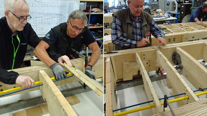
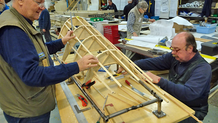
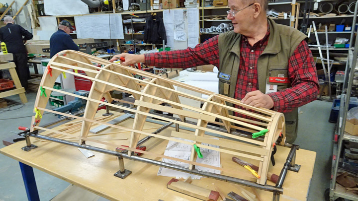
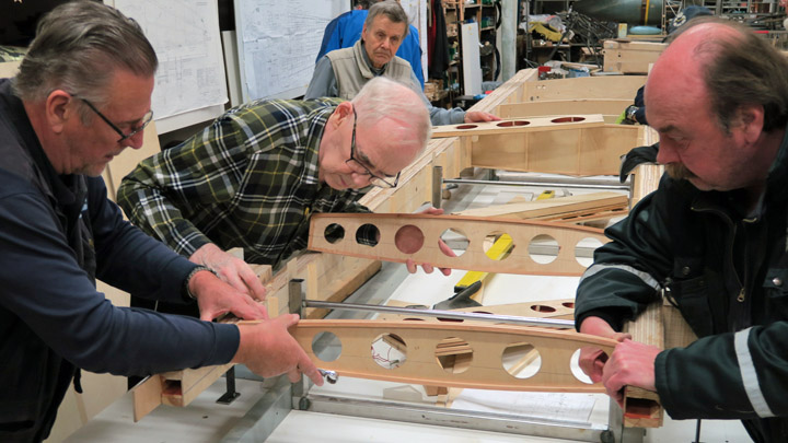
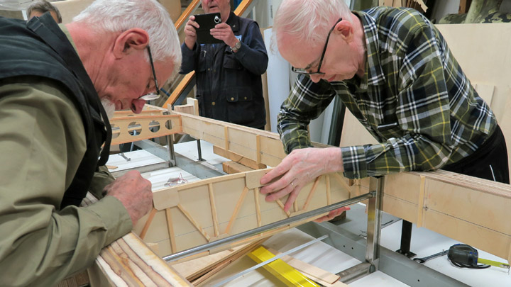
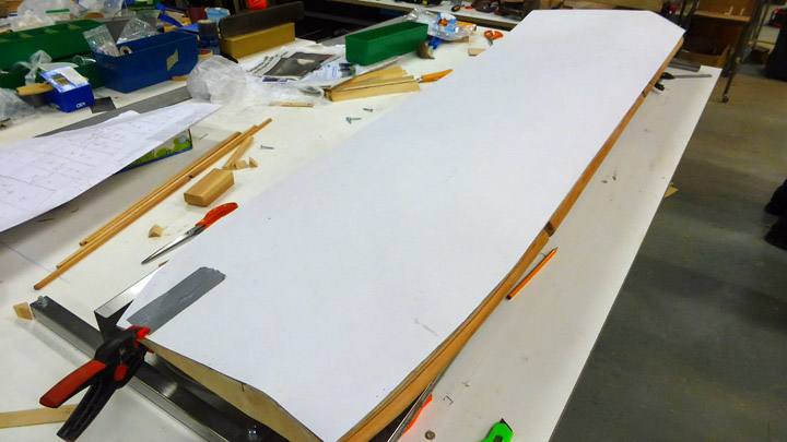
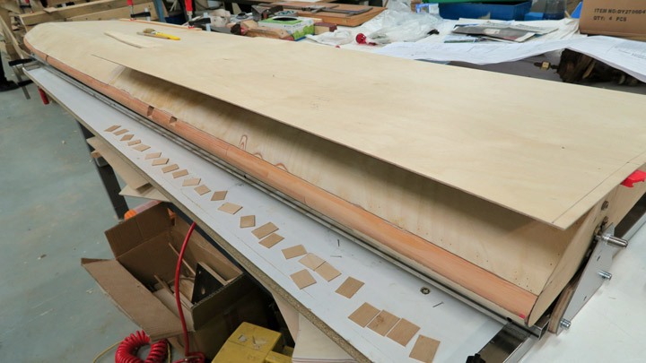
When the glue had dried, the installation of the supporting battens between the ribs could be started. The battens are installed on the ribs on the upper and lower side of the wing, covering the full length of the wing. Strips of plywood were glued on both sides of each rib, at the lower edge. Then the supporting battens were glued onto the strips.
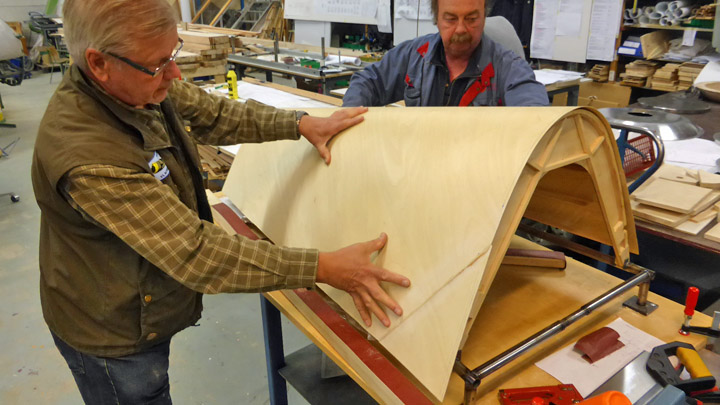
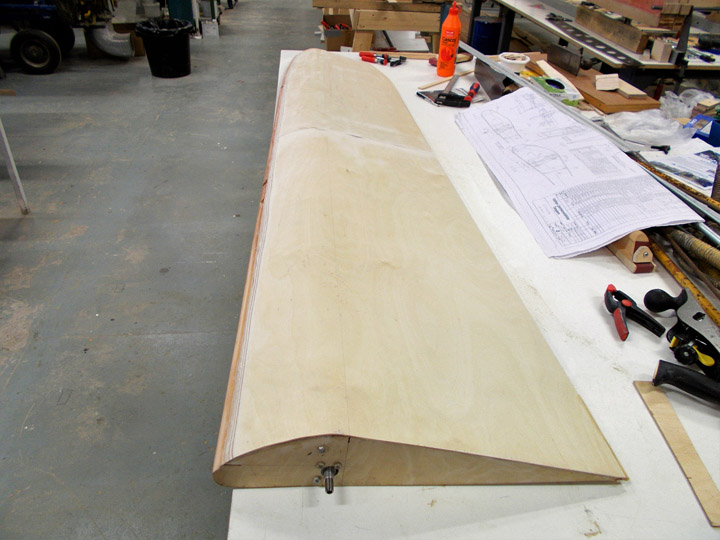
The battens on the upper side of the ribs will be installed when the wing has been turned around. Another supporting batten was added on the front side of the batten which penetrates the tips of the ribs. Now the tip batten became thicker and the front edge of the batten is at the level of the rib tip. The ribs were installed in a similar way on the leading edge of Myrsky’s both wings. Photos: Lassi Karivalo Translation: Erja Reinikainen |
|
Avainsanat: aviation history, restoring, old aircraft, VL Myrsky II, MY-14 |
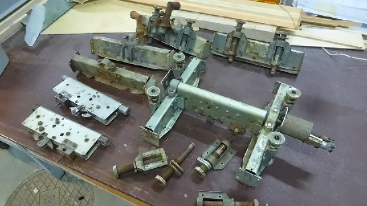
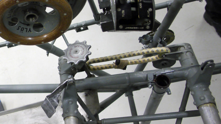
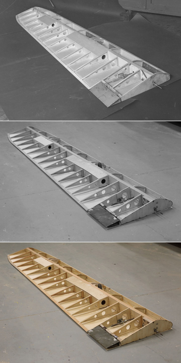
Rack for auxiliary fuel tank of Myrsky is testedMaanantai 14.1.2019 - Member of Tuesday Club The VL Myrsky fighter has inside both wings a rack for fastening an auxiliary fuel tank or a bomb. The Tuesday Club team had several original parts of the rack for the Myrsky restoration work. The rack parts were repaired and cleaned and assembled together to form the racks on both wings of the Myrsky and also for the short wing built for test purposes. The rack on the test wing has been already tested.
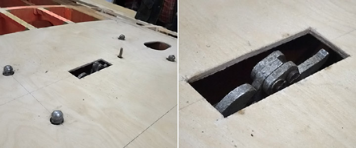
The racks had been installed on both wings on the Myrsky. The area around the rack had also been preliminarily covered with new plywood so that the rack could be tested. Holes were made into the plywood covering for the rack mounting locator pins and the catch, which the auxiliary fuel tank or the bomb is locked on. Another hole was made for the indication pin, which forwards the information to the pilot when the auxiliary fuel tank or bomb has been released.
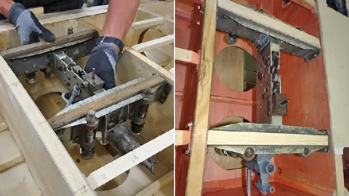
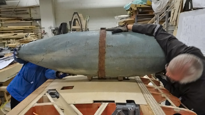
The testing of the rack could be done easily as the wings are on the assembly jig with the lower side upwards. For the test procedure the team could use an original Myrsky auxiliary fuel tank - fortunately a bomb wasn’t needed for the testing! The team decided to test the rack on the starboard (right) wing.
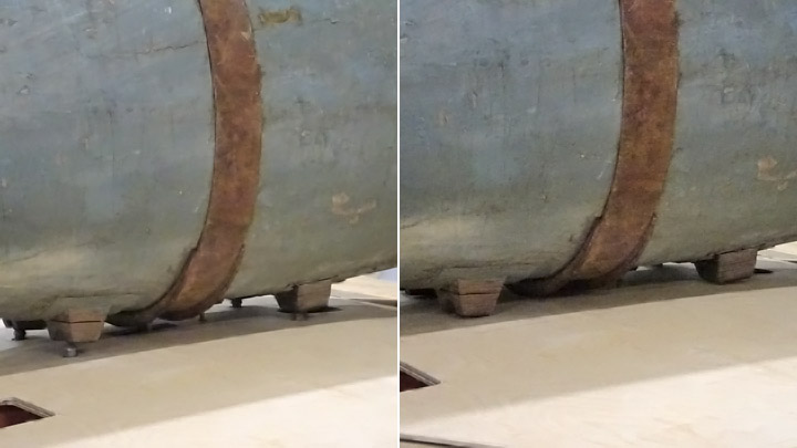
The auxiliary fuel tank was lifted upside down on the wing, which was upside down on the assembly jig. The tank was placed above the rack so that the four wooden steering blocks met the mounting locator pins, which penetrated the wing covering. The lock ring on the surface of the auxiliary fuel tank slid through the hole on the wing covering towards the lock catch on the rack.
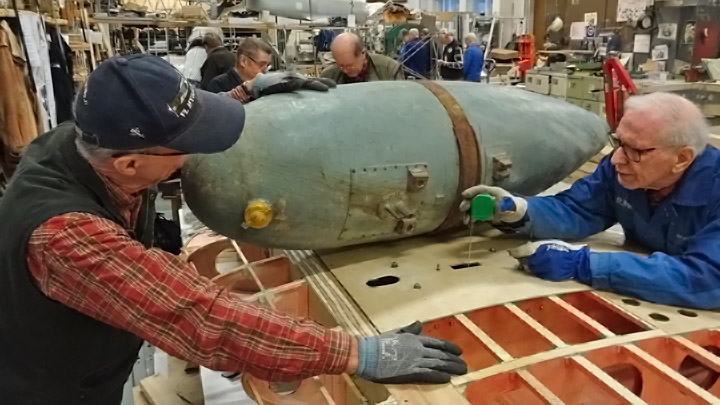
The team was annoyed to discover that the fuel tank didn’t lock on the rack. When the tank was lifted and the distance of the lock catch from the wing surface was measured, the team noticed that the rack, placed inside wing between two wing ribs, was located about 5 mm too deep. The lock ring of the auxiliary fuel tank didn’t reach the lock catch. Although the rack had been installed according to the measurements on the drawings, this was what the situation was.
The team sighed and continued working, dismantled the rack and installed it again, this time 5mm closer to the surface of the wing. The auxiliary fuel tank was tested again on its place, this time it locked perfectly on the lock catch of the rack. Photos: Lassi Karivalo Translation: Erja Reinikainen |
|
Avainsanat: aviation history, restoring, old aircraft, VL Myrsky II, MY-14 |
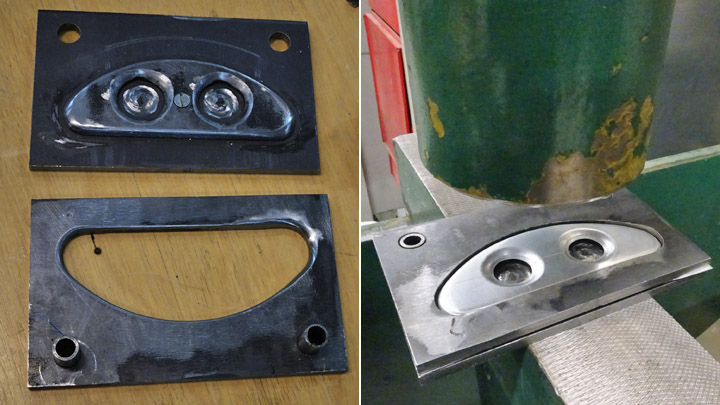
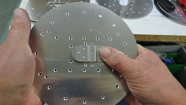
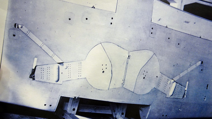
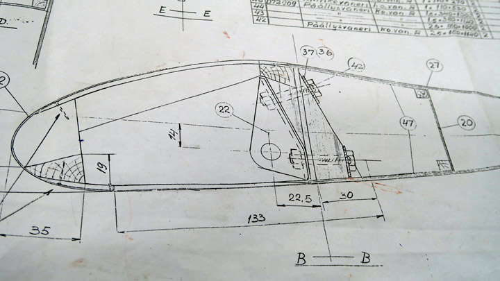
Hatch for Myrsky auxiliary fuel tank rack is being madeLauantai 8.12.2018 - Member of Tuesday Club There are several different inspection, maintenance and operation hatches on the wing of VL Myrsky II. There are four hatches for the auxiliary fuel tank racks which also served as bomb racks, two on either side. The hatches are made of 1 mm aluminium sheet. They are round and 17,5 cm in diameter. In the middle of each hatch there is an elongated lock disk, which has a spring and can be pushed open and closed using a finger.
The operation hatches of the auxiliary fuel tank rack have a complicated structure. Fortunately, the Tuesday Club team had a detailed original construction drawing for making the hatches. The drawing has been dated in November 1944, so it is from the time when the Myrsky planes were in production. Also one original auxiliary fuel tank rack hatch had been found. Other original hatches are not available.
The drawing on the auxiliary fuel tank rack hatch illustrates well how detailed drawings have been made even of the smallest parts when the Myrsky was designed. The drawing describes in detail the construction of the hatch and its parts, 12 of them in total. 42 rivets are needed when the parts are assembled together.
When the team started making the hatches for the Myrsky wings, billets for all the different hatches were cut from 1 mm aluminium sheet. Some of the hatches are round, some rectangular. A laser cutter was used for cutting the hatches. The exact shape and size of each hatch was programmed for the laser cutter and the data was fed into the cutter using a memory stick. The holes for the rivets were also cut using the laser, several rivets are needed to fasten the parts together. The advantage of the laser cutter is that the outcome is exactly according to the original drawing.
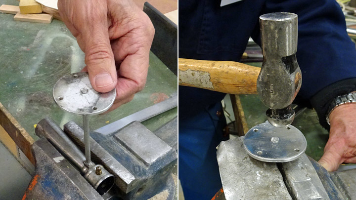
The first task of the team was to make the hatches for the auxiliary fuel tank and bomb racks. Six hatches are needed, two for each side and two for the Myrsky test wing. The first item to be made were the crescent-shaped stiffeners on the inside of the hatch. Twelve billets, slightly larger than the final stiffeners, were cut from 1 mm aluminium sheet. Two holes were cut according to the original drawing for making the stiffener lighter. For pressing the billets into shape, female and male pressing moulds were made. The billets were pressed into shape between the moulds.
The extra “skirt” was cut off.
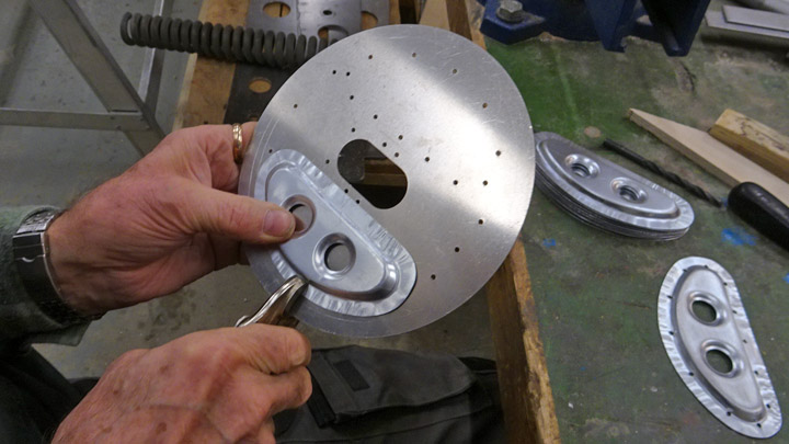
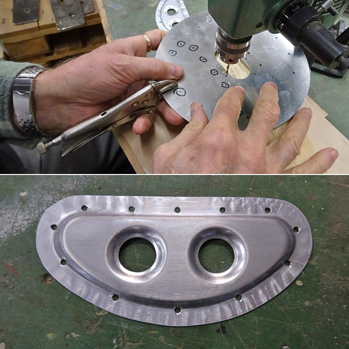
The following task was to drill rivet holes on the edges of the crescent-shaped plates, so that they could be riveted on the inside of the hatch. The stiffener was clamped tightly on the inside of the hatch plate, exactly on the right place. Then the hatch plate was turned around and the rivet holes for fastening the stiffener, already laser cut on the hatch, were marked using a marker pen.
The holes were drilled along the edge of the stiffener. Soon all 12 stiffeners were ready to be fastened on the hatch plates.
Another Tuesday Club team was working on the lock disks which will be placed in the middle of the auxiliary fuel tank hatch. The parts of the lock disk were riveted together and the lock disk was preliminarily placed into the opening in the middle of the hatch. A lot of work will be needed before the six auxiliary fuel tank hatches are ready, not to mention all the other hatches, which are at the billet stage. |
|
Avainsanat: aviation history, restoring, old aircraft, VL Myrsky II, MY-14 |
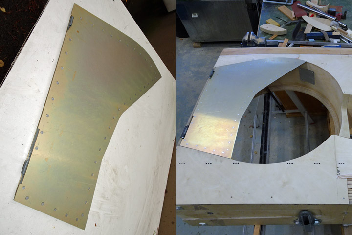
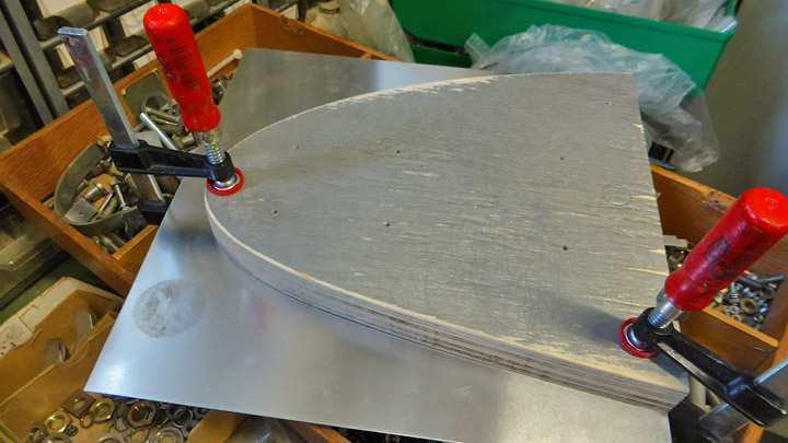
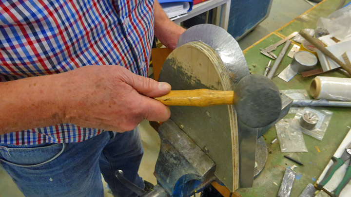
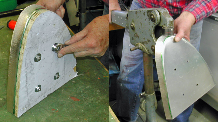
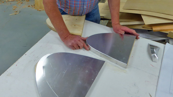
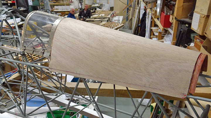
Lower sides of Myrsky's wing tips coveredSunnuntai 11.11.2018 - Member of Tuesday Club The VL Myrsky II (MY-14) is being restored by the Tuesday Club and its wings are nearly ready in the area between the wing spars. The upper sides of the wings have been covered between the spars, but the lower sides are still without plywood covering. The covering won’t be finished before all the equipment, tubes and wires have been installed inside the wing. However, the covering of the lower side of the wing tip could be partly installed. Here the wing tip part means the rounded end of the wing.
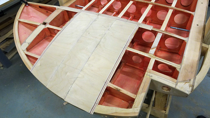
The upper side of the wing tip was covered with a single sheet of plywood, stretching over the whole wing tip area. This was possible because the upper surface of the wing tip is arched only in one direction. The lower side of the wing tip arches significantly upwards towards the tip and also sideways. This is the reason why the lower surface of the wing tip can’t be covered using one sheet of plywood: a large sheet can’t be bent properly into two directions.
The solution was to use narrow strips of plywood which are glued together. These strips of plywood can be bent to match the double arching form of the wing tip.
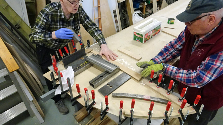
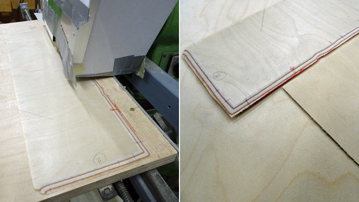
15 cm wide strips of 1,5 mm plywood were cut to match the length of the wing tip. The strips are be glued together using lap joints, so the edges of the strips were beveled (2 cm of the edge), using a mitre grinding machine. Before gluing, the inner surfaces of the strips were protected using polyurethane varnish, tinted red.
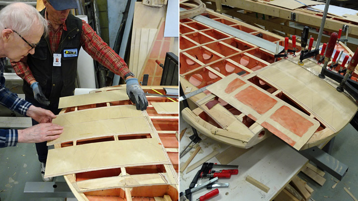
The plywood strips were glued into place one by one, starting in the middle of the wing tip. Heavy weights were placed on the strips after gluing. The plywood strips were clamped tightly on the rib and batten structures of the wing.
The whole lower side of the wing could not yet be covered because the navigation light wiring, etc. has to be installed inside the wing. The covering of the lower side of the wings has been started: three strips of plywood have been glued into place on both wings. |
|
Avainsanat: aviation history, restoring, old aircraft, VL Myrsky II, MY-14 |
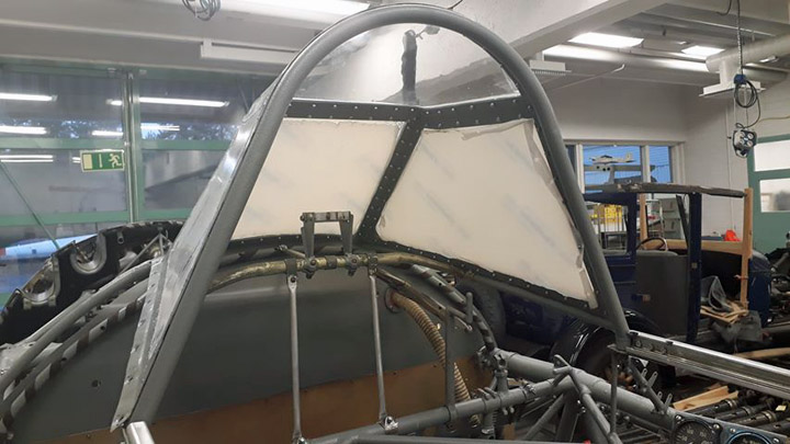
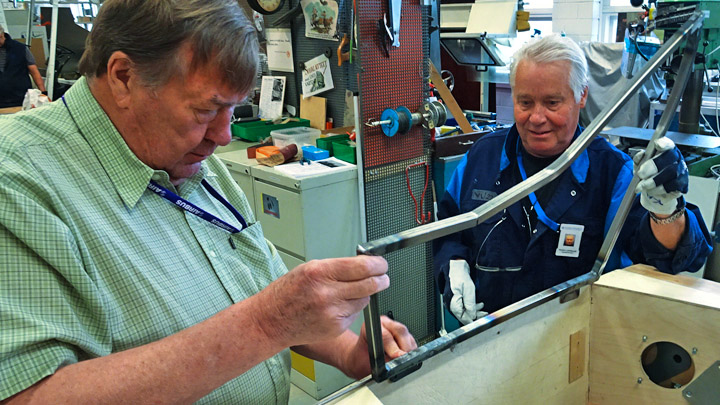
MY-14 got windscreenPerjantai 9.11.2018 - Reino Myllymäki Perspex or acryl or PMMA was found in the beginning of the 1930s. It got a tradename Plexiglas in Germany and Perspex in U.K. These tradenames led to generic name pleksi (in Finnish) or perspex (in English). Nowadays these generic names mean later innovations like polycarbonat (PC), too.
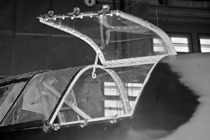
The VL Myrsky II restoration project has a windcreen already glazed with green frames. This item has been shown in several exhibitions. It is a spare part never used in any Myrskys. It might be installed to another aircraft and little changed. Therefore it won't be installed to the MY-14.
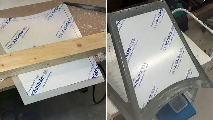
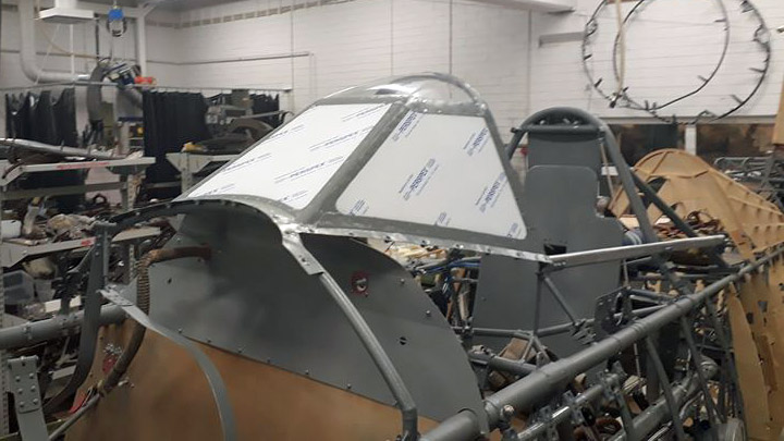
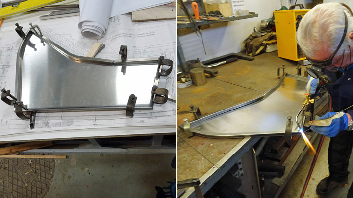
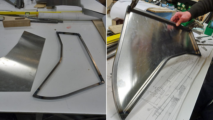
The restoration team of the Finnish Air Force Museum used another windscreen for the MY-14. The windscreen has four perspex plates: one arched and three straight plates. The arched plate is original and it was smoothed. The straight plates were disappeared and the team made new ones. The plate edges have rabbets so that the plate will be on the same level with the frame. The rabbets were made by a rabbet cutter.
The installation of the strainght perspex plates was the first stage, then the arched plates will be taken under construction. There were arched perspex plates in the windscreen, canopy and aft glazing. The installation of the gun sight is under construction, too.
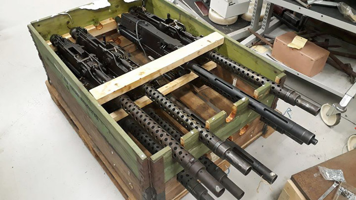
During the arrangement of the storage, the Myrsky's weapons were taken to wait the installation. There is two 12,7 mm LKk/42 heavy machine guns of VL Myrsky and six 12,7 mm Breda-SAFAT heavy machine guns of Fiat G.50 in same box in the photo. |
|
Avainsanat: aviation history, restoring, old aircraft, VL Myrsky II, MY-14 |
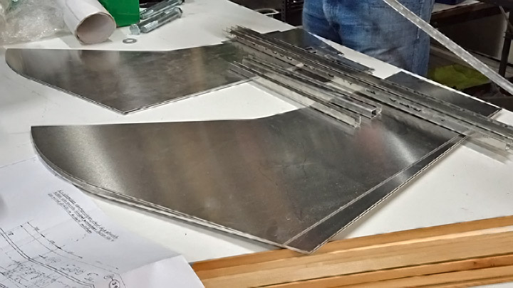
Wheel well cover of Myrsky?s test wing installedSunnuntai 4.11.2018 - Member of Tuesday Club The wheel well covers for VL Myrsky II (MY-14) wings have been under construction since spring. Three covers will be made: two for the actual Myrsky and one for the test wing.
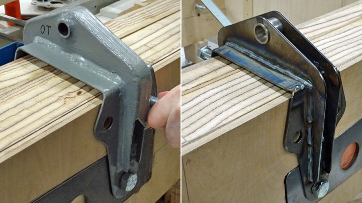
The wheel well cover consists of two sheets of aluminium and a supporting frame in between, made of 15mm steel tubes. The aluminium sheet on the inside is slightly smaller than the outer sheet. Rivets are used to attach the aluminium sheets to the supporting structure so that the cover forms a box construction. The wheel well cover is attached to the edge of the wheel well with two hinges. The hinges are fastened on the edge of the steel tube structure of the cover.
During this autumn the wheel well cover for the test wing has been under construction. The assembly of the wheel well cover, and the function of the hinges will be tested on the test wing before making the covers for the actual Myrsky wings.
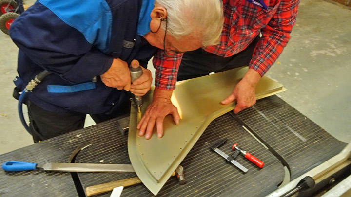
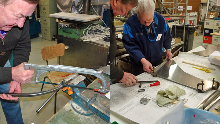
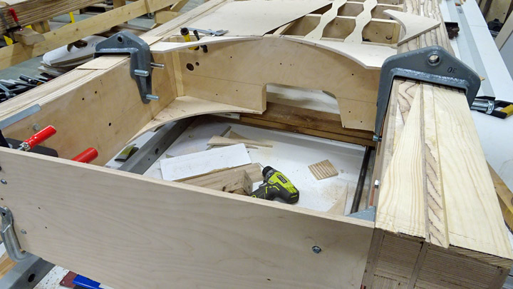
The steel tube structure was made first, then the hinges were welded on the frame and then the cover structure was assembled into the wheel well hole. The hinges were fastened to the edge of the wheel well to see how the cover fits and functions. Several modifications were needed, and the position of the hinges had to be changed before the assembly team was happy with the result. When the correct position of the hinges on the tube frame had been found, the aluminium plates could be riveted on the frame.
The aluminium plates and the tube structure were clamped together, into a tight package. Holes for the flush rivets were drilled along the edges of the cover so that the drill penetrated both aluminium sheets and the tube construction between them. The holes are about 4cm apart and their edges were bevelled with a drill so that the rivet tops will be at the same level as the aluminium sheet top.
Before riveting the aluminium sheets were sent to be chromed. Chroming forms a thin organic layer on the surface of the aluminium and protects it from oxidation. The chromed surface is an excellent foundation for painting work. The chroming was not done by the Tuesday Club.
When the chroming had been done, riveting could be started. 20mm long flush rivets were used. A pneumatic riveting hammer was used when placing the rivets one by one into the holes on the wheel well cover. No problems occurred during the riveting work and the aluminium sheets and the steel tube frame soon formed a box construction. The cover could be fastened on the edge of the wheel well by installing the hinges. When the cover was closed, it fitted tightly into the wheel well opening.
The next step in the restoration work will be to assemble a spring mechanism into the wheel well under the cover. This mechanism will push the cover open when the landing gear is taken out. A lever will be installed on the inside of the cover to close the cover. When the landing gear is pulled in, the wheel of the gear will push the lever and the wheel well cover closes. |
|
Avainsanat: aviation history, restoring, old aircraft, VL Myrsky II, MY-14 |
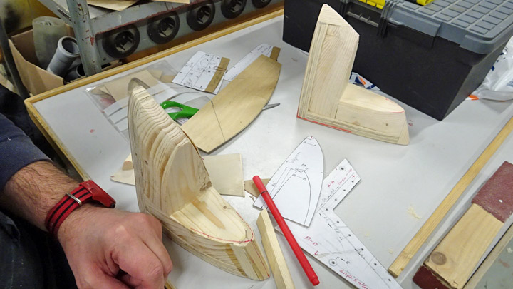
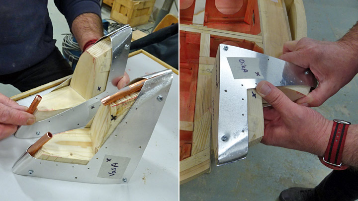
Ongoing activites at Myrsky wingtipSunnuntai 28.10.2018 - Member of Tuesday Club In the restoration work of VL Myrsky II the installation of the navigation lights is under way. When the tip of the wing was built, a gap was left on the front corner of the wing so that the navigation lights could be installed later.
The navigation light on the wingtip consists of a transparent aerodynamically designed plexiglass cover and its frame, made of aluminium, which attaches the cover onto the wing structure. The actual navigation light bulb is inside the cover, surrounded by a small red or green plastic cover.
The plexiglass cover of the navigation light is made in a vacuum moulding machine. The heated 2mm pvc plexiglass plate is pressed on a mould which has the shape of the navigation light cover. When the plexiglass has cooled on the mould, it is cut into shape.
The mould for the navigation light cover was made from wood. Pieces of wood were glued together to form a piece large enough for the moulds of the navigation light covers on both wings. The piece of wood was cut and milled following drawings so that it had the shape of two navigation light covers, back to back. When the desired shape had been reached, the piece was cut into two parts. Now the moulds for the two light covers were ready.
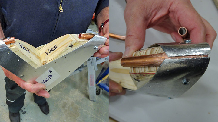
The cover is assembled into the gap at the wingtip using a frame made of aluminium sheet. For the making of the frame a mould is needed, following the shape of the plexiglass cover. The aluminium frame is made of two halves, upper and lower, which are welded together around the mould. Also in this case the mould was made from wood, matching the shape of the navigation light cover.
The upper and lower halves of the aluminium frame were screwed onto the wooden mould and the ends of the two halves met correctly. A piece of copper tube was placed under the ends of the frame halves to protect the mould from excessive heat when welding the parts together. The tube also forms a solid base under the frame edges when the welding is done.
Some additional work is still required before the navigation light cover mould is ready: it needs a supporting structure before it can be attached to the vacuum moulding machine. The mould for the aluminium frame is ready and the halves can be welded together to form the frame. |
|
Avainsanat: aviation history, restoring, old aircraft, VL Myrsky II, MY-14 |
Both wings of Myrsky are being assembledLauantai 9.6.2018 - Member of Tuesday Club In the beginning of this year the Tuesday Club of the Aviation Museum Society has been working on the Myrsky project and the main emphasis has been in assembling the left wing of Myrsky MY-14. The test wing has also been under construction and some metal parts have been made too. The left wing has been assembled in a steel framed assembly jig where the wing spars have been firmly fastened. The area between the wing spars was built in the jig and the areas of the leading and trailing edge will be built later.
In the beginning of May the left wing was at the phase where the area between the wing spars was nearly ready and its upper surface covered with plywood. At this point the wing didn’t need the support of the jig anymore and could be unfastened. A lifting support was built from steel tubes for both ends of the wing before unfastening and moving it from the jig. The supports were necessary because the wing is too heavy to be moved manually.
Photo: Jorma Laakkonen. When the wing had been unfastened from the jig, it was lifted by the supports at the ends of the wing using a forklift and a manual lift and moved on a wooden working platform. The wing was also turned upside down so that the covering of the lower wing surface can be started.
Photos: Jorma Laakkonen. The covering of the wing was started by building the supporting battens for the plywood covering. This means fastening the lines of lengthwise battens between the wing ribs. The plywood covering is glued on these battens and secured by screws.
The construction of the battens was started by gluing plywood rests on the upper edge of each rib. The battens will be installed on these rests and the ends will be glued on the ribs. The battens were glued one by one as “bridges” between the ribs. By the end of May the installation of the battens had been completed and the actual covering of the area between the wing spars could be started.
The aim is to have the covering ready before the left wing will be placed on display in the VL Myrsky-project exhibition at the Finnish Air Force 100th Anniversary Airshow. Also the test wing built by the Tuesday Club will be on display there.
When the left wing was unfastened from the jig, it can be used for assembling the right wing of Myrsky. Now the Tuesday Club team had reached the point where both wings of Myrsky can be built and assembled simultaneously and side by side in the restoration room of the Finnish Aviation Museum.
The construction of the right wing in the jig will follow the same procedure as for the left wing. The wing will be built in the jig until the area between the wing spars is ready and the leading and trailing edges will be built later.
The wing spars of the right wing were fastened on the jig and the ribs were installed between the spars. The ribs had been ready and waiting for some time for the wing assembly to begin. The ribs were easily installed and the wing construction began to take shape. The metal brackets for the landing gear system were fastened on the wing spars and ribs and the fuel and air pipes of the auxiliary fuel tank were pushed into place through the holes in the ribs.
When the fuselage with engine, the left half of wing and the test wing are on the show in the Finnish Air Force 100th Anniversary Airshow on June 16th and 17th 2018, there is on the show the biggest Myrsky assembly since 1965. See you there! Photos (execept when separately mentioned): Lassi Karivalo. |
|
Avainsanat: aviation history, restoring, old aircraft, VL Myrsky II, MY-14 |
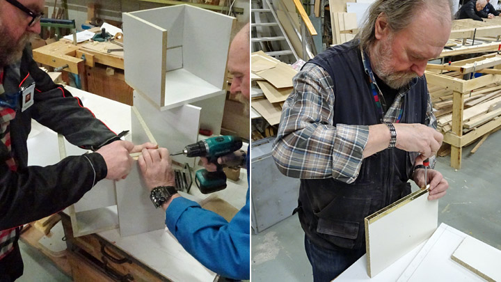
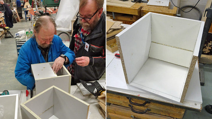
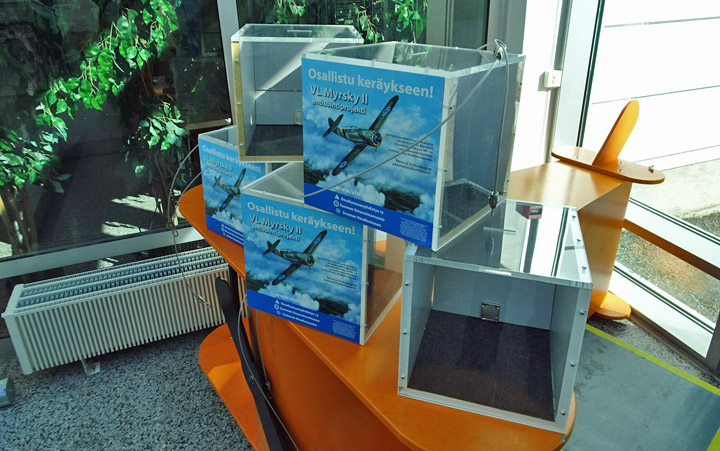
Money collection boxes for Myrsky project are readyMaanantai 2.4.2018 - Member of Tuesday Club The Aviation Museum Society is arranging a fund raising campaign for the VL Myrsky restoration project, the campaign began in December 2017 and it ends at the end of November 2018. Five new money collection boxes are needed for the campaign. The Tuesday Club was given the task to make the partly transparent money boxes. First the model of the money box was designed at the Tuesday Club. The starting point was the existing collection box which is in the lobby of the Aviation Museum. Also the suitable existing materials in the museum material storage had to be taken into account, e.g. old melamine surfaced shelves and thick transparent Perspex sheets. The collection box was designed to have its sides, bottom and back wall made of 20 mm thick melamine surfaced chip board and its top and front wall of thick plexi. The box is cubicle in shape and its dimensions are 30x30x30 cm. The dimensions were determined by the existing Perspex sheet which was 30 cm wide. The back wall of the box consists of two parts and the upper and lower parts are joined together with a hinge. The lower part of the back wall is used as a hatch to empty the donated cash from the box. The team decided to build first one test box. Pieces were sawn to measure from the old melamine covered shelves to form the bottom, sides and back wall. Then the bottom and sides were assembled together. After minor adjustments the parts were attached using Erikeeper Plus glue and screws. Then the back wall was cut in two parts to make the hatch. The upper and lower parts of the back wall were connected to each other using a piano hinge. The upper part was attached between the sides of the box using glue and screws. A lock was installed on the openable lower part of the back wall and a hole for the locking beak was made into the bottom plate of the box.
The team was pleased about the way the test box looked and “mass production” to build the other four boxes could be started. The bottoms, sides and back walls for all four collection boxes were sawn from the existing shelves. The frames of the four boxes with the openable hatches were built following the model.
As old melamine covered shelves had been used to build the boxes, the sides of the chip boards had to be covered to make them look nice. White covering strip was used for the sides, it was glued into place using the heat of a flat iron. Before the plexi pieces were installed to form the front wall and the top, a piece of carpeting was glued on the bottom of the box as padding.
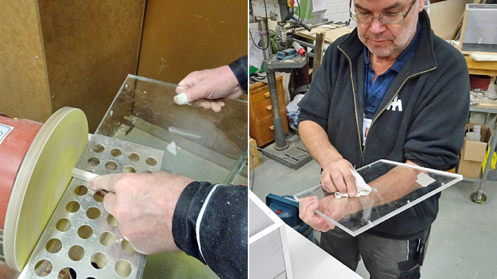
The front walls and roofs for all five collection boxes were sawn from 30 cm wide and 7 mm thick Perspex sheets. The sawn edges of the plates were buffed out.
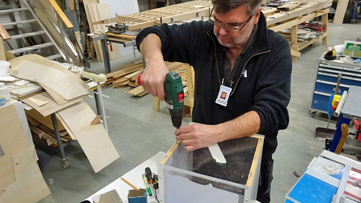
The transparent parts were fitted into place in each box. A rectangular opening was milled in the middle of the roof sheets, this would be used for dropping cash into the box. The transparent surfaces were thoroughly cleaned before assembling the plexis on the boxes using screws.
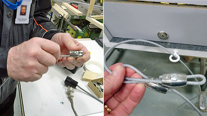
To prevent the stealing of a donation box, 4 mm thick plastic covered steel wire was purchased for each box. Each box also needed two wire rope grips for the loops at each end of the wire. The loops were needed for the padlock. An eye hook was attached on the back edge of the bottom plate and the wire was threaded through. The aim is to attach the money box to a nearby structure and lock it in place using the wire and the padlock.
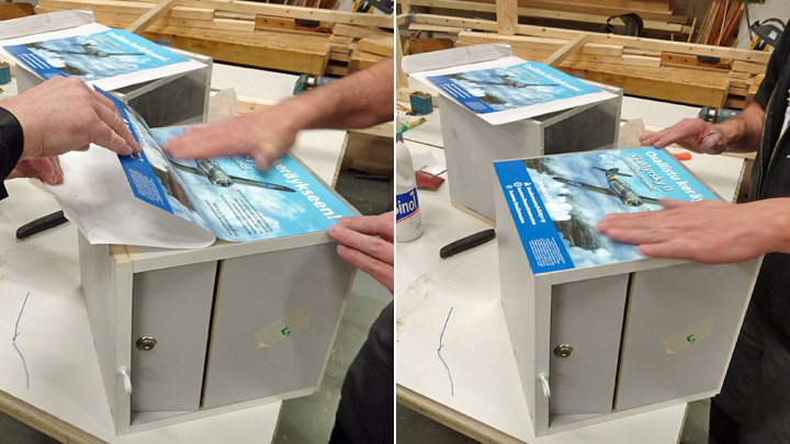
The work was concluded by attaching stickers on both sides of each box, introducing the Myrsky project and the permit for the fund raising campaign.
The money collection boxes of the VL Myrsky restoration project are now ready. When you see such a box, made by the Tuesday Club, you have a good opportunity, even a responsibility, to drop some money into the box and support the VL Myrsky II restoration project. |
|
Avainsanat: aviation history, restoring, old aircraft, VL Myrsky II, MY-14 |
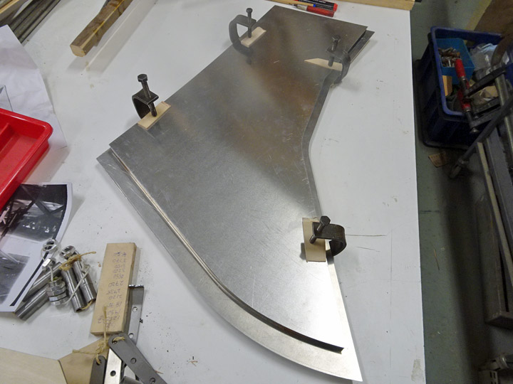
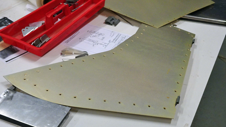
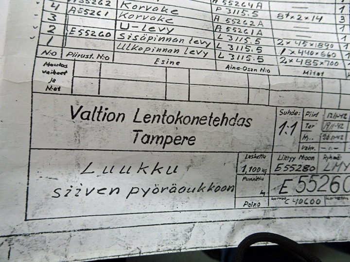
Myrsky's daisy cutters under constructionSunnuntai 25.3.2018 - Member of Tuesday Club The test wing in the VL Myrsky II restoration project has progressed to the phase where the construction of the mainwheel inner door (“the angel wing”) has been started. In the original VL Myrsky drawings this part has been named “hatch” but the word “door” has been used in this translation. The inner door covers about half of the wheel well. The other half is covered by the mainwheel door, which is attached to the landing gear leg and covers half of the wheel.
The opening and closing mechanism of the mainwheel door operates like this: when the landing gear is pulled into the mainwheel well inside the wing, on its way in the wheel pushes a lever on the mainwheel door which closes the door. The outer edge of the mainwheel door fairing presses against the inner door fairing, shutting it firmly. When the landing gear is taken out, the inner door linkage mechanism pushes the door automatically open using spring load.
The mainwheel inner door in Myrsky has box construction. It consists of two aluminium fairings with a supporting metal frame in between. The inner door fairing is 2 mm thick aluminium plate on the outside and 1mm thick aluminium plate on the inside. The outer measurements of the inner fairing are 440x660 mm and those of the outer fairing 485x700 mm, so the inner fairing is smaller than the outer. This means that the outer fairing forms a flange at the edge of the fairing.
Some hinge mechanisms of daisy cutters have been survived but the doors not. Therefore the doors have to be manufactures as new production. There is metal frame between the inner and outer fairing of the mainwheel inner door. It runs along the edge of the inner fairing. The aluminium fairings are attached to the frame by riveting. Originally the Myrsky mainwheel inner door had an open U-shaped aluminium frame structure, on which the fairings were separately riveted. A different structure was chosen in the Myrsky restoration project. The supporting frame between the fairings is made of 15x15mm rectangular steel tube. The outer and inner fairing are attached to the frame with rows of rivets penetrating the frame. Rows of holes are drilled into the supporting frame for the rivets. The test wing in the Myrsky project is a wing half, couple of meters long, and it has only one mainwheel well. Therefore only one mainwheel inner door is needed for the test wing. The Tuesday Club team decided, however, to build three doors: one for the test wing and two for the actual Myrsky (which naturally has two mainwheel wells).
The work was started by laser-cutting the fairings according to their accurate measurements: the three outer fairings from 2 mm plate and the three inner fairings from 1 mm plate.
Then the supporting frame structures were made. Pieces matching the inner fairing measurements were cut from 15x15 mm rectangular steel tube. Three sets of pieces were cut, one set of pieces for each “daisy cutter”. Some of the tubes had to be bent to match the curving edges of the inner fairing.
The frame pieces were placed along the edge of the inner fairing of the mainwheel inner door and attached to it using small clamps. Then the work continued in the “welding space”, i.e. a sea container outside the Finnish Aviation Museum where the pieces were welded together to form the frame along the edge of the inner fairing. A similar procedure was used to weld the two other frames.
Now the mainwheel inner door supporting frames and inner and outer fairings were ready. The next phase will be to rivet the fairings onto the frame. |
|
Avainsanat: aviation history, restoring, old aircraft, VL Myrsky II, MY-14 |
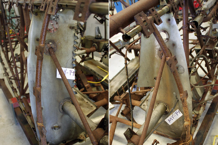
Alodine 1200 S and MY-14Tiistai 20.2.2018 - Reino Myllymäki Suomeksi There were several different process in order to enhance the corrosion protection of aluminium alloys in the 1940s. For example, the bulkheads may got either VLO 32742 part 40 and 41 processes (anodic treatment and bichromating) or part 42 process (treating in chromium nitric acid).
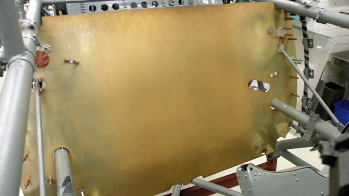
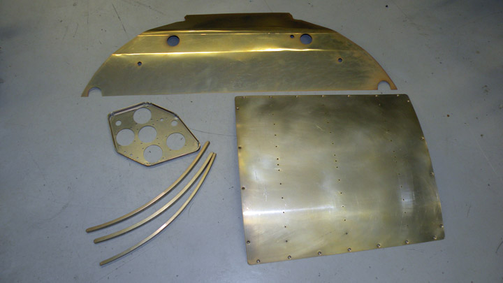
That kind of processes or agents were not in use anymore. MY-14's bulkheads are reproduced from new material by using design drawings and survived parts of bulkheads. Now they were yellow chromated by Alodine 1200 S process. Same process was used for the bottom access panel and instrument panels.
Alodine 1200 S process for MY-14's parts was provided by Patricomp Oy. Photos: The Finnish Air Force Museum. |
|
Avainsanat: aviation history, restoring, old aircraft, VL Myrsky II, MY-14 |
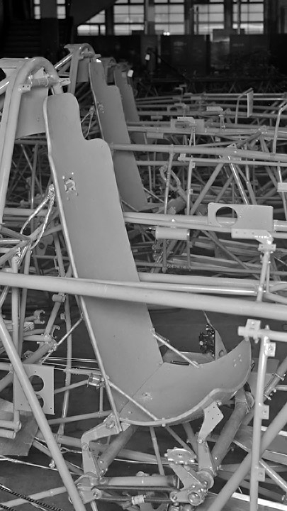
Armoured pilot's seat of VL MyrskySunnuntai 18.2.2018 - Reino Myllymäki Before WWII, the fighter pilot's seats were normally not armoured. However, Russians were predecessors. The Finnish Air Force started the armouring during the Winter War, mostly that work was concluded before the Contiuation War. For example, the pilot's seat armours for Gloster Gladiator II biplane fighters were ordered on February 26th 1940 and for Morane-Saulnier M.S.406 monoplane fighters on March 5th 1940. Furthermore, Hawker Hurricanes were armoured after Winter War and the armouring of Brewster is totally own story. The Finnish Air Force ordered 100 armoured pilot's seat from Swedish Avesta steel factory. These seats were intended to 50 Fokker D.XXIs ordered from the State Aircraft Factory but they were suitable for Fokker C.Xs, too. Now we know that the pilot's seat of Fokker D.XXI and VL Myrsky were same kind of. That means that VL Myrskys could have pilot's seats made in Avesta. These armours were 10 mm thick.
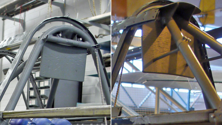
The armour of the VL Myrsky's pilot's seat is three-piece. Pilot's head armour is fixed to the upper part of the steel-tube fuselage frame. Other two pieces form the pilot's adjustable seat.
The original pilot's head armour of the MY-14 has preserved as a part of the steeb-tube fuselage frame. Photos: Reino Myllymäki.
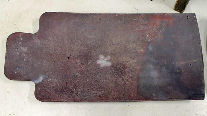
The armoured back rest is an original part but it has been in a crashed Fokker D.XXI fighter. It has been straightened and needs some changes.
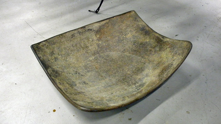
However, the armoured seat was lacking. It was produced as new production part by a subcontractor. Brewster 239's seat was used as a model since the drawings of the seat lacked. The result looks like original!
The brackets of the seat lacked too, but luckily the drawings were preserved. Mr Matti Patteri converted the drawings to the cutting files by CAD and the brackets' blanks were cutted by laser by Prolaser Oy. Blanks were welded by the restoration team at the Finnish Air Force museum. The armoured pilot's seat will be covered by felt, flannel and pegamoid. The felt will be glued to the seat.
Photo: Reino Myllymäki Some parts such as the adjusting screw and sandums were conserved or restored earlier and are now fixed to the MY-14. Photos: Historic photo: archives of the Finnish Aviation Museum. Other photos unless separately mentioned: the Finnish Air Force Museum. |
|
Avainsanat: aviation history, restoring, old aircraft, VL Myrsky II, MY-14 |
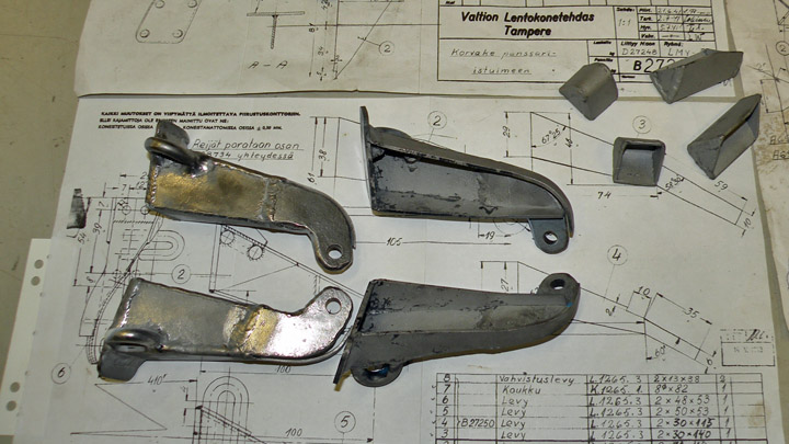
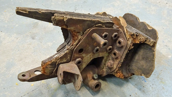
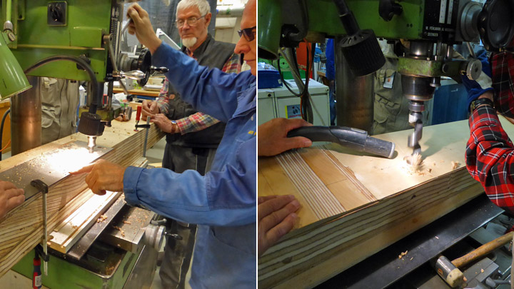
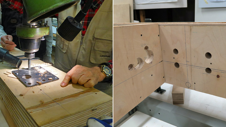
About metal parts of Myrsky wingsPerjantai 16.2.2018 - Member of Tuesday Club There are many metal parts in the wooden wing structure of the VL Myrsky. The majority of these metal parts connect to the wing structure and the parts have to be installed at the same time when the ribs of the wing are attached between the wing spars.
Several of the metal parts are involved in the fastening of the landing gear at the root of the wing. These parts include e.g. the fastening of the diagonal rear strut of the landing gear which is attached to the rear spar, the fastenings of the landing gear strut which are attached to the seam of the fourth rib on the rear and front spars and the bearing and locking disc of the retracting actuator of the landing gear which is fastened on the front side of the front spar. The metal brackets, which fasten the wing to the fuselage, are fastened on the upper edge of the front and rear spars. In the mid-wing area there are also the fuel and compressed air tubes for the auxiliary fuel tank and the trimming mechanisms for the ailerons.
Some of the existing metal parts of the wing are original parts which have been installed in a Myrsky. They come from the wings of Myrsky which have been stored in the forest and decayed there for decades. The parts were salvaged from the forest, the moss was removed and the parts were cleaned, sand-blasted and painted grey. Also the original bolts and nuts belonging to these parts were salvaged and cleaned to be used again.
All of the metal parts needed for the wing were not found, so the missing parts have had to be made. The original parts and their drawings have been used when making the new parts. New parts have been needed to fasten the landing gear and also to fasten the wing to the fuselage.
There are four metal brackets on the upper edge of the front and rear spars which are needed to attach the wing to the fuselage. This means that when the Myrsky fuselage will eventually be placed on top of the wing, only four bolts will be needed to lock the wing and fuselage together.
Before the front and rear spars of the wing were fastened on the assembly jig, holes were drilled for the landing gear fasteners and for the bolts connecting the brackets of the wing and fuselage. When the wing spars had been fastened on the assembly jig, the installation of the ribs and the metal parts was started. It didn’t take long before all the metal parts had found their place and had been fastened on the wing spars.
The fuel and compressed air pipes of the auxiliary fuel tank were collected from the Finnish Air Force Museum. The original parts were rusty and had to be honed clean. The fuel tubes were painted yellow using a standard colour (Dicco 6 / RAL 1003 Signalgelb) typical for tubes on an aircraft and the compressed air tubes were painted blue. Then the tubes were pushed in place through the holes in the ribs. |
|
Avainsanat: aviation history, restoring, old aircraft, VL Myrsky II, MY-14 |
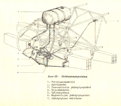
Aluminium rib and oil cooler in left wing of MyrskyPerjantai 2.2.2018 - Member of Tuesday Club
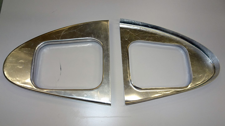
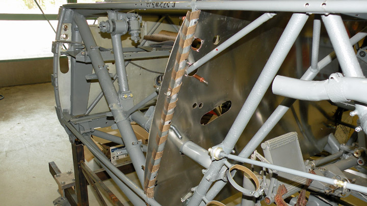
Photo: Photo archive of the Finnish Air Force Museum The oil cooler of the Pratt&Whitney R-1830 Twin Wasp engine in VL Myrsky is located in the lower part of the engine mounting, in front of the foremost wing spar. The cooling air is led in through a three-port air intake opening in the leading edge at the root of the left wing. The supply air flows from the air intake to the cooler in an air duct. From the other end of the cooler the warm exhaust air flows through an air duct to the exhaust opening which is located on the lower surface of the leading edge on the right wing.
At the root of the left wing the end of the air duct is attached to the leading edge rib which is made of aluminium plate. The other ribs of the leading edge are made of plywood. The aluminium rib has a hole with a flange matching the size of the air duct.
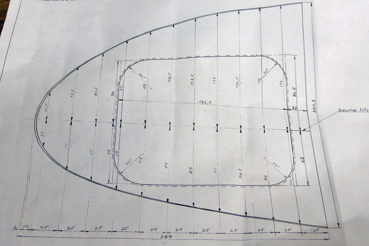
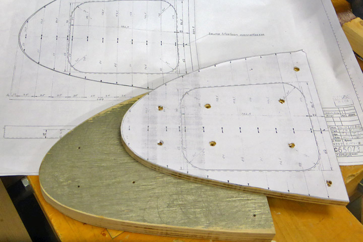
One of the tasks in the Myrsky restoration project was to build this aluminium rib. The drawings of the rib were available, so fortunately precise instructions for the task existed. First a mould had to be made in order to be able to bend the rib into its final shape.
The profile of the rib was cut out from a paper copy of the drawing and glued on thick plywood. Tracing the edges of the drawing two similar rib-shaped plywood pieces were sawed. The mould was needed to bend the edges of the aluminium plate rib so that they form a rim 22 mm wide.
The plywood mould was used to draw the shape of the rib onto 1 mm aluminium plate and 22 mm was added around the shape for the rim. The preliminary shape of the rib was cut and attached tightly between the two plywood moulds.
The following step was to bend the overlapping edge of the aluminium plate over the edge of the mould to make the rim. The plate was forced carefully to bend using a rubber hammer so that the aluminium wouldn’t break at the pleat / knuckle.
When the edge had been roughly bent, the rim was forced to its final shape using a sheet metal shrinker. The outer edges of the rib were now ready and the work could proceed to the next phase.
A hole for the air duct was made to the middle of the rib, following the dimensions in the drawing and taking into account the width of the flange for attaching the duct. The shape of the hole was drawn on the rib. The hole was made by first drilling a line of small holes following the drawn shape and then cutting along the holes using plate shears. The plywood mould of the rib was needed again: a similar hole was made in the middle of the mould. The aluminium rib was fixed tightly between the moulds. Then the edges of the hole in the aluminium plate were preliminarily bent against the edge of the plywood mould to form the flange and the final forcing was done using the sheet metal shrinker.
Now the rib for the leading edge at the root of the left wing was ready. Two similar ribs were made – one will be installed on the test wing and the other on the actual Myrsky wing. Photos: unless separately mentioned: Lassi Karivalo |
|
Avainsanat: aviation history, restoring, old aircraft, VL Myrsky II, MY-14 |
Restoration is none straightforward work - funny stories from workshopKeskiviikko 31.1.2018 - Reino Myllymäki Aviation Museum Society visited in the Finnish Air Force Museum on Saturday 27th January 2018. There was possibility to visit in the workshop where the VL Myrsky fighter MY-14 is restored. The progress during the first half of the year 2017 was remarkable. During the last half the team has had other duties, too. Therefore the progress has slowed down a little. Almost all original parts are fastened to the aircraft.
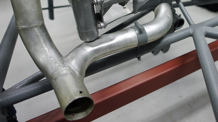
The original cockpit ventilation pipe has been found but it was dented. The straightening work was big. Especially a dent behind curves was laborious to be straightened. When the straightened pipe was fastened, it was easy to note that foot controls will hit to it. The original production drawing has disappeared but according to the installation drawing, the pipe has no dents. It is possible, that the needed dent has been hit in the production.
Another pipe laborious to be straightened, is located in left hand side of the cockpit. An aluminium pipe changes shape from round to oval.
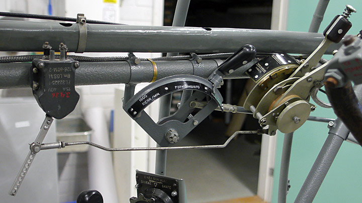
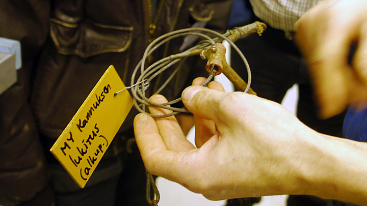
During the storage cleaning a rod with a special shape was found. It was easy to identify. It is a connection rod between the throttle lever and an electricity switch needed to warn the pilot when the engine idles and the landing gear is up. The orginal part is now installed and substitutes already installed reproduction part.
Another original part, which was found after production of the new part, is the locking wire of the tail wheel. The reproduction part has been allowed to stay in the MY-14. The original part ensured that the reproduction part has been produced right way.
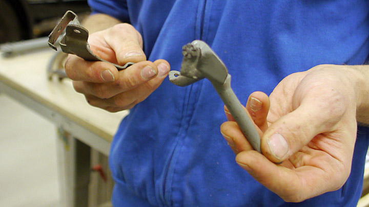
A very interesting part was found in the storages. After another unidentified part was found, both of them could be identified. They were brackets of the manual starter. One is bracket of the hand crank and another is part of a reserve clutch. The will be installed in the MY-14.
The pilot seat of the VL Myrsky has sandums. Since the rubber features are different in warm and cold, the aircraft has different sandums for summer and winter use. However, it is possible that same sandums were used all year. |
|
Avainsanat: aviation history, restoring, old aircraft, VL Myrsky II, MY-14 |
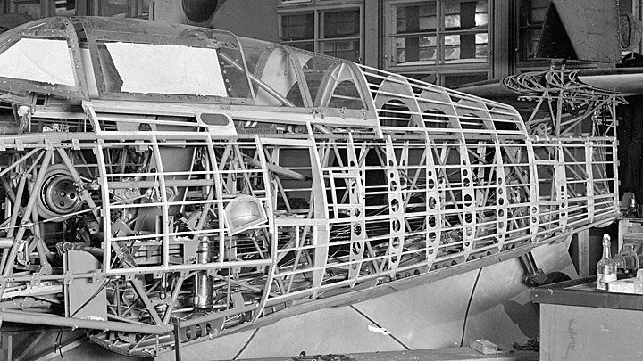
Myrsky rear fuselage coveringPerjantai 26.1.2018 - Member of Tuesday Club The VL Myrsky is a fighter plane having mixed construction. The wings are made of wood and the fuselage consists of a tubular steel frame covered with a covering structure that gives the aircraft its shape. The rear fuselage covering consists of wooden upper, lower and side skin panels which are attached to the steel tube frame construction. The covering consists of wooden arc-shaped formers and wooden stringers and the skin is made of 1.2 mm plywood.
Photo: Finnish Aviation Museum photo archive In the first Myrsky serial production individuals the lower, side and upper coverings of the rear fuselage were built directly onto the tubular steel frame. Later the lower and upper coverings were pre-built on an assembly jig and attached onto the frame in one piece. The sides, however, were still built directly onto the frame of the plane. The upper skin plywood panel in the rear fuselage of Myrsky doesn’t meet the upper edge of the side skin panel in a butt joint but slightly overlaps the side panel. In a similar way the side skin plywood panel’s lower edge overlaps the upper edge of the lower panel’s upper edge. This is how the rear fuselage covering has a lap joint structure.
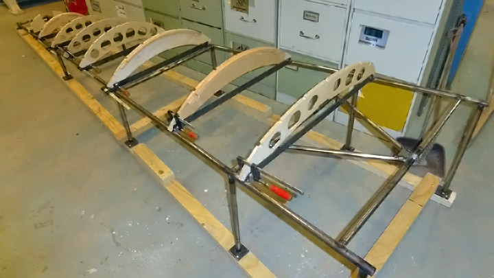
The Tuesday Club built tubular steel frame assembly jigs for assembling the upper and lower coverings of the Myrsky. The jig dimensions match accurately the dimensions of the Myrsky steel frame construction. This ensures that the upper and lower coverings which are completed on the jig will fit precisely the Myrsky tubular frame.
The assembly of the rear fuselage upper covering was started in the Tuesday club by attaching the formers on the jig. The wooden formers have been made in the youth workshop operated by the city of Vantaa. The jig frame has brackets for attaching the roots of the formers in the correct position. Corresponding brackets exist on the Myrsky steel frame.
When all the formers for the upper covering were in place, the wooden stringers connecting and supporting the formers were attached and modelled to their final shape.
When the formers and stringers had been glued together, the upper covering skin plywood could be preliminarily installed. The skin on the upper and lower covering will be finished later.
The upper and lower coverings without the plywood skin have already been preliminarily assembled on the Myrsky MY-14 fuselage at the Finnish Air Force Museum.
Photo: Finnish Air Force Museum The Tuesday Club has made two rear fuselage coverings for the Myrsky. Why two? One covering belongs to the Myrsky MY-14 which is under restoration. But what about the other one? It will be assembled on the less famous Myrsky MY-5 steel frame. The MY-5 frame is one of the four existing but damaged Myrsky tubular steel frames.
The MY-5 steel frame has been reserved for the model wing which has been built in the Myrsky restoration project. The model wing is the 2,5 m long root part of the right wing. When the model wing is completed, it will be attached to the MY-5 frame. The MY-5 frame will also have another model wing: the root part of the left wing, about 1 m long which will be built in the restoration project. The other rear fuselage upper covering which was made now will be assembled on this frame. Maybe the Tuesday Club will have the energy to build also the lower and side coverings for the MY-5... The Myrsky MY-5 frame with its short model wings and upper coverings will eventually be placed on display at the Finnish Aviation Museum. At the moment the MY-5 tubular steel frame lies unrestored at the Finnish Air Force Museum in Tikkakoski. Photos: Unless separately mentioned: Lassi Karivalo. |
|
Avainsanat: aviation history, restoring, old aircraft, VL Myrsky II, MY-14 |
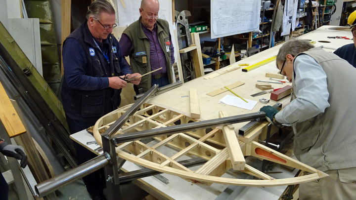
Myrsky wing begins to take shapeTiistai 7.11.2017 - Member of Tuesday Club The Tuesday Club of the Finnish Aviation Museum Society has finally reached the phase when the renovated Myrsky MY-14 wing is assembled. To reach that point a lot of work has been necessary - to build the wing spars and ribs. The building of the wing spars has taken 2,5 years and they were finished in late spring 2017. Building the ribs took 650 hours of work.
Before the wing spars could be attached to the wing assembly frame (the jig), some holes had to be made for the feed-through and fitting of equipment which will be later installed into the wing. Holes are needed for machinery and equipment which operate e.g. landing gear, guns, bombs and auxiliary fuel tank, ailerons, etc. The frame of the wing will first be built between the wing spars, including the equipment inside the wing, before the leading and trailing edges are assembled.
During the autumn the main work item has been to make the holes into the wing spars. At the same time supporting braces for the ribs have been installed between the front and rear spars. The connecting steel plate joint of the wing halves has been under construction as well. The original Myrsky wing was 11 meters long and weighed 440 kilos whereas the renovated Myrsky wing will consist of two parts, this solution was chosen mainly for practical reasons.
The matching imbedding and holes for the bolts attaching the connecting steel plates were made to the attachment point of the wing halves, i.e. the root of the wing spars. It is important to attach the steel plates to the spars at the correct angle so that the two wing halves will form a uniform wing which corresponds to the original Myrsky drawings.
On Tuesday October 17th 2017 all preparations had been made to attach the Myrsky right wing spars to the assembly jig. The assembly jig made of steel beams and pipes cut to measure had been prepared well in advance. First the rear spar was attached to the jig and then the front spar. The spars were locked in place using steel rods installed across the jig frame.
When the wing spars were firmly attached to the jig, the preliminary installation of the wing ribs between the spars took place. The ribs had been made last spring. They were not yet glued in their places at this phase.
As a proof of Tuesday Club work quality, the ribs settled firmly and tightly in their places between the spars. The upper edges of the ribs were also in line – this was noted by placing a steel ruler on top of the ribs.
The wing spars attached to the assembly jig and the ribs between them are an amazing sight. This is an important milestone for all the Tuesday Club members who have been involved in the building of the Myrsky wing. This moment almost corresponds a “topping out” in a house construction. |
|
Avainsanat: aviation history, restoring, old aircraft, VL Myrsky II, MY-14 |
Covering work of Myrsky aileronsSunnuntai 29.10.2017 - Member of Tuesday Club The aileron frames of VL Myrsky II (MY-14) had been finished in the Tuesday Club by the beginning of September. The ailerons were built according to the original Myrsky drawings. A pair of photographs proves this: an original photo of a Myrsky aileron from the State Aircraft Factory and a photo taken of the aileron made by the Tuesday Club. However, the Tuesday Club used modern Casco Outdoor wood glue.
The ailerons of an airplane often have fabric covering even if the plane itself has duraluminium or plywood covering. On the plywood-covered Myrsky the ailerons were also plywood-covered. According to the original drawings the ailerons had 2,5 mm plywood covering in the area between the aileron spar and the aileron’s leading edge but 1,5 mm plywood in other areas. At the aileron’s leading edge the front edge of the plywood covering reached about 3 cm over the wooden leading edge strip. The seam of the 2,5 mm and 1,5 mm plywood plates was located on top of the aileron spar.
When the aileron covering was discussed at the Tuesday Club, the decision was to use a structure different from the one on the original drawings. The 2,5 mm plywood would be difficult to bend into the curving shape of the aileron’s leading edge so instead of the original material thickness, 1,0 mm plywood - which is easier to bend - would be used first to cover the area between the aileron spar and the wooden leading edge. Then the whole aileron would be covered with 1,5 mm plywood. Using this method there would be no need to bend the thick plywood at the aileron’s leading edge and also the plywood seam on top of the aileron spar would be avoided. The original material thicknesses (2,5 mm and 1,5 mm) in the different areas of the aileron would be reached as the result of combining the two plywood layers. The Tuesday Club wondered why the Myrsky designer had originally chosen a more complicated and structurally weaker method to cover the aileron.
The right wing aileron was covered first. A piece of 1,0 mm plywood was cut to measure, matching the area between the aileron spar and the aileron’s leading edge covering the whole length of the aileron. Some milling work was required before the piece could be fitted to its place. Then the plywood covering was glued into place. Two-component epoxy glue was used with some cellulose fiber added. The glue was spread on the surfaces of the aileron spar, the ribs of the leading edge and the leading edge batten and the plywood covering was pressed on them.
A compressed air stapler was used to make sure that the plywood covering fixed tightly onto the aileron structure. To avoid the staples to drive too deep into the covering plywood, small additional pieces of plywood were placed between the staples and covering. When the glue had dried the staples and the protecting pieces of plywood were removed. Then the front edge of the plywood on top of the aileron’s leading edge and the rear edge on top of the aileron bar were ground thin and slightly slanting.
Now the covering the whole upper surface of the aileron with 1,5 mm plywood could be started. The decision was to use two pieces of plywood and to place the seam in the middle of the aileron. In front of the aileron spar the plywood is attached to the 1,0 mm plywood which was already in place. In other areas of the aileron the thicker plywood would be glued onto the aileron spar, ribs and the trailing edge batten.
First a cardboard pattern was made, matching the area of the aileron. Two pieces from the 1,5 mm plywood were cut based on the pattern. The plywood pieces were milled and fitted into place for gluing. The covering plywood piece closer to the wing root was glued into place first and after that the piece toward the wing tip.
When gluing, the plywood pieces were first attached to the aileron spar using a couple of nails to keep the pieces in the correct position. Then epoxy glue was spread on the plywood which had already been installed and on the spar and the 1,5 mm plywood was pressed tightly against them. Staples along the edges of the plywood and the spar ensured that the plywood was tightly attached.
The work continued to fix the rear part of the plywood onto the aileron structures. Epoxy glue was spread on the ribs and on the trailing edge batten and the plywood was pressed against them. A heavy steel plate was placed on the plywood as weight and clamps were used to press the read edge of the plywood against the trailing edge batten.
When the glue had dried the clamps and staples were removed. Finally the front edge of the plywood on top of the aileron’s leading edge was ground slightly slanting to match the curved shape of the leading edge.
Now the upper side of the right wing aileron had been covered and the following phase will be to cover the lower surface of the aileron. Before that the inside of the upper surface and the inner structures of the aileron have to be protected with varnish. The lower side of the aileron will be covered using a similar method as was used on the upper surface. When the right wing aileron has been covered, the work on the left wing aileron will be started. |
|
Avainsanat: aviation history, restoring, old aircraft, VL Myrsky II, MY-14 |
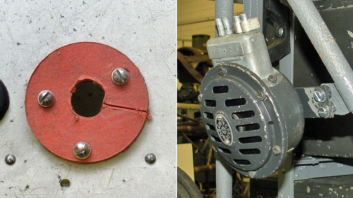
Screws and plasticsTiistai 8.8.2017 - Reino Myllymäki You can check the success of the restoration work of old aicraft by looking the screws. If you will find some Torx or Phillips screws, something has went wrong. The Phillips (PH) screw was invented by John P. Thompson who sold his invention to the Phillips Screw Company in 1935. Although 85 % of U.S. screw manufacturers have sold the licence in 1940, the State Aircraft Factory did not use Phillips screws in VL Myrsky. The Pozidriv (Pz) is derived from the Phillips screw and it is therefore an younger invention. Phillips and Pozidriv screws are almost past now, since the 1967 invented Torx (Tx) is a common solution now. So, VL Myrsky has no PH, Pz or Tx screws. Only slot head screws and hexagonal head bolts.
The slot head screws of the State Aircraft Factory in connection with a Parkesine abrasion shelter and the alarm buzzer. Photos: Finnish Airforce Museum. Do not ignore plastics! You can find selluloide "windows" in the aircraft of the 1920s. VL Myrsky has maybe none selluloide parts but Parkesine has been used in VL Myrsky as buttons and abrasion shelters. The Parkesine was invented in 1856 and the selluloide in 1870. Selluloide has been used as film material until asetate substituted it in 1950s.
The propeller controllers button has made from Parkesine and the instruction panel from Paxolin. Photo: Finnish Airforce Museum. You can find a lot of Bakelite or phenol formaldehyde resin from the VL Myrsky. Some buttons are made from casted Bakelite. Paxolin is a composite material of Bakelite and paper. Paxolin has used for example in the instruction panel of the propeller controller. The most important use of Bakelite is plywood. Theodor Goldschmidt invented Tego-film in late 1920s. Tego-film is Bakelite extracted in a silk paper. German manufacturers did not succeed in plywood manufacturing by Tego-film. But the Finns succeed accidentially in 1929. Before WWII Finland was the second greatest plywood manufacturer in the World. The number one was Soviet Union. It was possible to produce weatherproof birch plywood and laminated veneer lumber by Tego-film. Veneer lumber was used in propeller blades, antenna mast, spars and tail strucure. Birch plywood was used in spars, ribs, tail structures and in the cover of the wing and the fuselage. The diagonal plywood was used, too. The grain direction has turned 45 degrees in the diagonal plywood.
The cabin aft glazing and canopy have been made from Plexiglas. Photo: Finnis Aviation Museum. The third - or is it fourth? - plastics used in VL Myrsky is acrylic (PMMA). It was invented in 1928 and commercialised as Plexiglas in 1933. The canopy and the cabin aft glazing have been made from acryl. It is possible to made curved shapes from acryl. However, it is not very durable material. Nowadays the polycarbonate (PC) is more durable but also more expensive material. The polycarbonate was invented in 1898 but commercialised after WWII. |
|
Avainsanat: aviation history, restoring, old aircraft, VL Myrsky II, MY-14 |
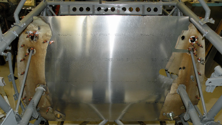
Cockpit bulkhead for MY-14Torstai 27.7.2017 - Reino Myllymäki VL Myrsky has two aluminium bulkheads. The front bulkhead is vertical and it is located just after the engine stand. The rear bulkhead - the cockpit bulkead - is inclined and is located in front of the cockpit. The engine with accessories is located in front of the front bulkhead. There is between bulkheads a space for the fuel tank, the oil tank, cartridge boxes and the box for spent cartridge cases - and the veapons.
After WWII the aluminum plate was expensive and therefore the middle parts of the cockpit bulkheads of the MY-5, MY-9 and MY-14 have exploited and only the borders are left. These parts have lot of through holes with Parkesine abrasion shelters.
The restoration of the cockpit bulkhead started from drawings. The shape of the bulkhead transferred to a cardboard. The existing parts of the bulkheads set against the drawing. The shape of the bulkhead was correct but some of the through holes were in different places. Some holes were coated by riveted aluminium discs and now holes were made in new places. All of them was modelled to the new bulkhead.
The new bulkhead was made from 0,4 mm duraluminum plate by using the cardboard as a model. The needed thorough holes were made and the abrasion shelters were made from the original Parkesine. Some of the thorough holes had rubber barrels and they were renewed by using partially original spare parts. The original aluminium coating discs were exploited except one which destroyed during the dismounting. The restoration work of the cockpit bulkhead is incomplete. |
|
Avainsanat: aviation history, restoring, old aircraft, VL Myrsky II, MY-14 |
Ilmailumuseot.fi - Aviationmuseums.fi