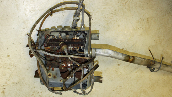
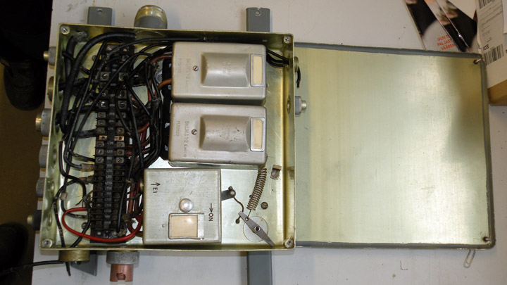
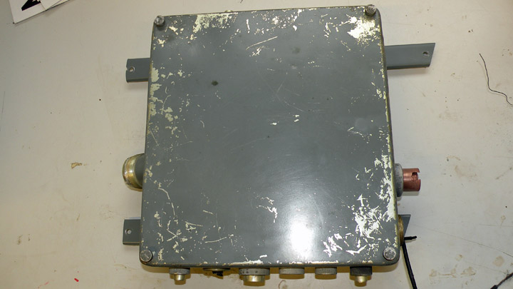
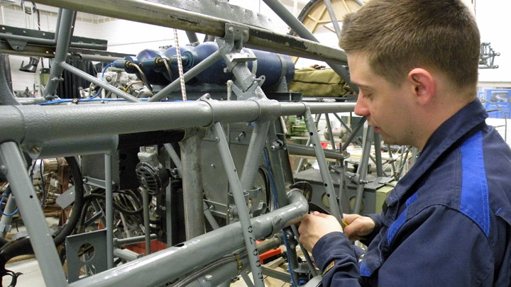
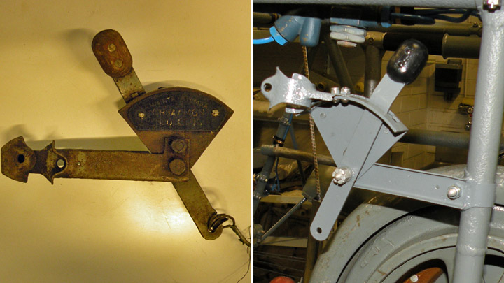
Switch box of landing gear motor for MY-14Torstai 20.7.2017 - Reino Myllymäki Not long ago I found a design principle of VL Myrsky: They tried to use mechanic and electric systems and avoid pneumatic and hydraulic systems. Only landing gear wheel brakes are hydraulic and the fuel transfer from drop tanks to the main fuel tank is based on compressed air. All other systems are either mechanic or electric. There are three electric motors: starter, gill adjustment motor and the motor of landing gear and flaps. According to the guidelines of the steering committee of the VL Myrsky II restoration project the mechanism of the landing gear system will not be complete. The landing gear will be moved in and out but not electrically. The reason for that is that almost all parts of the system are missing and the aircraft will stay over landin gear in the show. The complete system would be very expensive. When the aircraft has a electric motor, it has switches and switch box, too. The switch box of landing gear's electric motor is situated near the motor and the battery in the rear part of the cockpit.
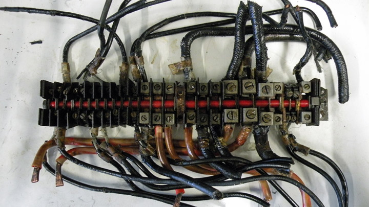
The switch box of the MY-14 is still alive ... at least almost. The box is twisted and in poor condition. Instead of it, a useless original switchbox has been taken to be the basis of the restoration work. One Siemens LMS 1-2 solenoid switch has been found in the Finnish Air Force Museum and another in the Hallinportti Aviation Museum. The covers and the main switch were found in the storages of the Finnish Air Force Museum. The switch panel has taken from the switch box of the MY-14.
The switch panel was disassembled, cleaned by phosphoric acid and LPS oil and the locked up screws were opened. The Bakelite marking strip was cleaned and the new markings were painted on white. The parts of the main switch were blasted by glass balls and the rebound cable was renewed.
The main switch was cleaned by soda blasting and equipped by the base plate of the original switch. The solenoid switches got base plates of the original switch box, too. The base plates had to be straightened and cleaned by soda blasting.
The mounting brackets were straightened, blasted by glass balss and painted first by strippin lacquer and then by the paint finish. The box was cleaned by washing agent and Miraclean. The result was protected by Renaissance vax. The fixing screws were straightened.
Finally, the switch box was fixed to the fuselage. |
|
Avainsanat: aviation history, restoring, old aircraft, VL Myrsky II, MY-14 |
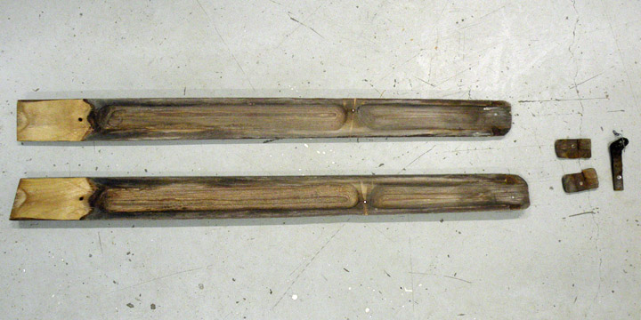
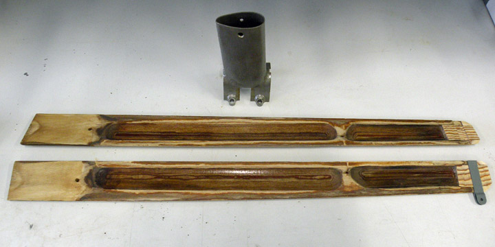
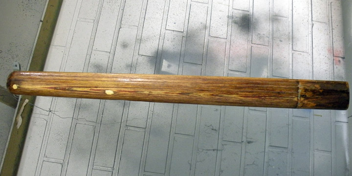
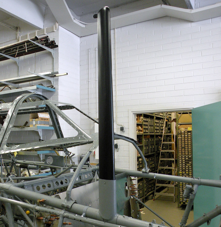
VL Myrsky has wooden aerial mastTiistai 18.7.2017 - Reino Myllymäki The aerial mast is on the right side of the front fuselage. The aerial cable is drawn between the mast and the vertical tail. The aerial lead-in is in the rear part of the canopy aft glazing.
It is hard to imagine that the material of the aerial mast is wood. Exactly, the material is the laminated veneer lumber made from birch veneer and Bakelite.
The aerial mast of the MY-14 has survived. OK, without painting and now almost splitted. The mount for cable was corroded as well as the root bracket.
The restoration of the aerial mast was started by straightening the joint surface between halves by planing. The wooden filling block of the top of the mast was renewed according to the drawing and the original part.
The cross section of the mast is like a drop. The mast has been lightened by making two cavities to both halves. There is none wirings and therefore the only one reason for cavities is lighten the weight. The cavities were cleaned and lacquered by Isotrol.
The mast halves were glued together by an epoxy resin. The outside of the mast was cleaned and lacquered. The cable mount was renewed according to drawings and the original part. The original root bracket was blasted by glass balls and lacquered. After that, the mast was fixed to the bracket by a slot-headed screw look like the original.
According to the remaininig paintings, the aerial mast has been painted first completely gray and after that the wooden part has been painted to black. The restoration work followed that observation. The result looks like the aerial mast in old photos.
In addition to propeller blades and the frame of the boardin step, the aerial mast is the fifth original wooden part of the MY-14. Historical photo: via Kalevi Keskinen, others: The Finnish Air Force Museum. |
|
Avainsanat: aviation history, restoring, old aircraft, VL Myrsky II, MY-14 |
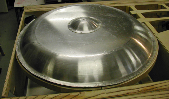
Potplate and engine for MY-14Lauantai 15.7.2017 - Reino Myllymäki VL Myrsky II has a 0,75 mm thick domed steel plate between the engine and the engine stand. It directs air stream and protects fuel tank, cartridges and cockpit against fire. There is no remaining pot plates of VL Myrsky II. Therefore it has to be made. Antero Flander from Flanco Oy in Rautalampi started the work. He made the potplate according to the drawing E61328. Some finishings were lacking but all parts and markings concerning needed cuttings included to the delivery.
There is one blog about pot plate: 13.3.2016. The pot plate was finished at the Finnish Air Force Museum workshop to correspond to the report for amendment number C302 and drawing E61328-I. According to the repair description dated October 30th 1944 the top of the pot plate of the MY-14 has converted to detachable. The pot plate has been cut in two places and a hole was cut for the carburettor air intake. Needed holes for screws were drilled and the seams were strenghtened by strips. The flanged nuts were riveted. The edges of the hole for the carburettor air intake were strenghtened by strips and equipped with a leather border.
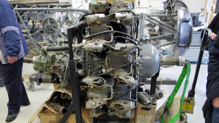
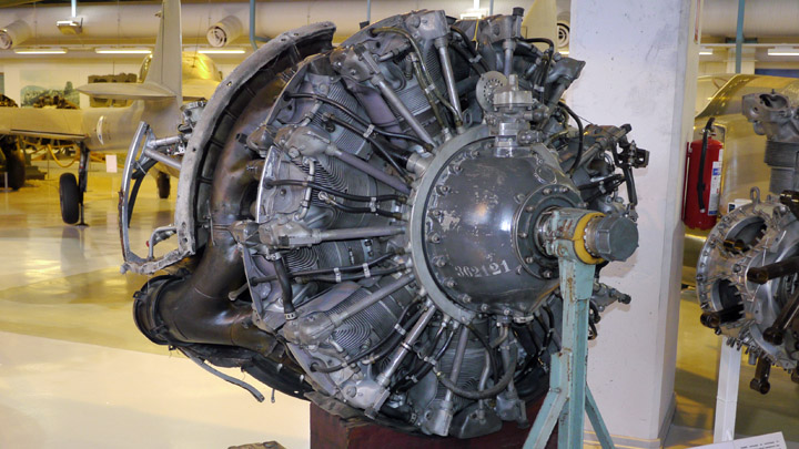
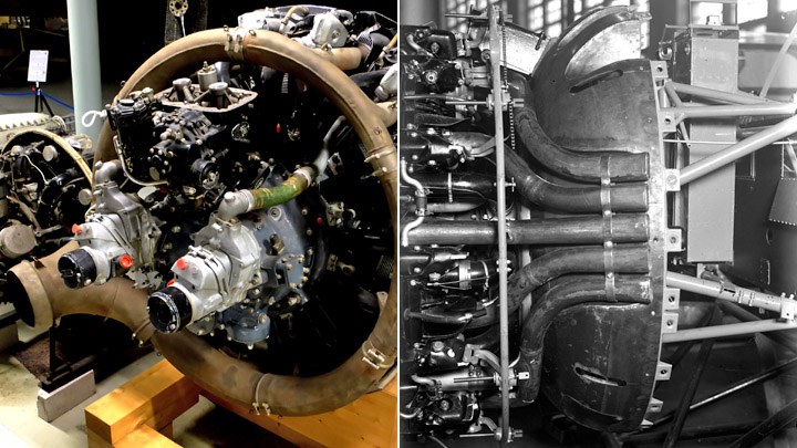
The engine stand was otherwise usable but the vibration observers were too poor and the bolts were disappeared. The barrels of the observers could be restored. The vibration observer rubber of the VL Myrsky II is equal to one used in the Fokker D.XXI with Twin Wasp Junior engine. However, the hole for bolt is bigger. By using an original part as a model, a drawing has benn made and Korja-Kumi Oy in Tampere manufactured new rubbers according to the drawing. The barrels were restored but needed bolts, nuts and washers were bought from a hardware store. A STW C3 engine has been installed to the stand. The STW C3 is a Swedish-built copy of the original Pratt & Whitney R-1830 SC3-G engine. The weight of the engine was 653 kg and a truck was needed in the installation work. Firstly, the project tried to acquire a pure SC3-G engine for the MY-14. Although at least 127 engines were bought to Finland, none was survived! An alternative S1C3-G engine has been in Douglas DC-3 passenger plane and stored years at the Finnish Aviation Museum. During the fall 2016, a second alternative has been found: STW C3 of the Saab B 17A target tug aircraft.
STW C3 engine in the workshop of the Finnish Air Force Museum. "I thought during last winter, that STW C3 is the most authentic engine for MY-14 in Finland", said conservator Harri Huopainen from the Finnish Air Force Museum. But the engine was not complete and needed a lot of work.
The engine of MY-14: a S1C3-G engine from the show of the Finnish Air Force Museum. Due to that, the former DC-3 engine type S1C3-G from the show of the Finnish Air Force Museum has been chosen for the MY-14. The only difference between SC3-G and S1C3-G is the rated altitude of maximum boost. According to FAA´s flyer A-699, the SC3-G can be converted to S1C3-G by changing the fuel and by adjusting the ignition timing. So, the fixed engine needs to be removed... First photo: Antero Flander, others: Reino Myllymäki. |
|
Avainsanat: aviation history, restoring, old aircraft, VL Myrsky II, MY-14 |
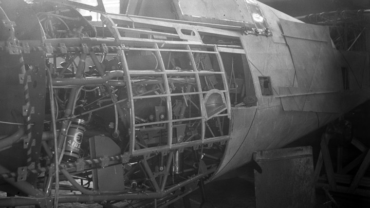
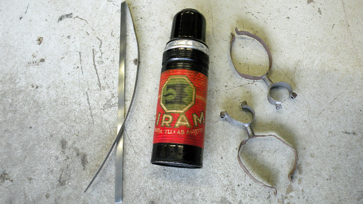
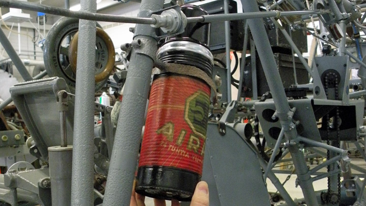
Why there is thermos bottle in structure of Myrsky?Torstai 13.7.2017 - Reino Myllymäki If you look at the old photos of the VL Myrsky II, you can find a thermos bottle in the middle of the studs, wires and pipes. What is the function of that Airam thermos bottle?
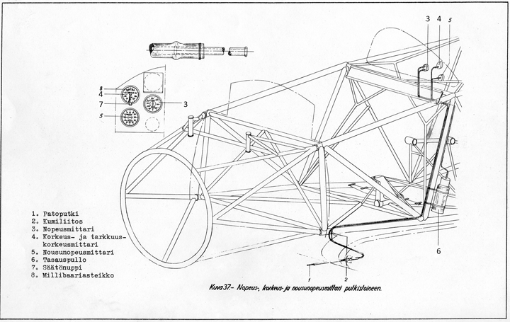
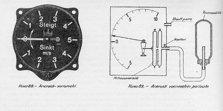
The Airam thermos bottle is a balance bottle of the variometer. The variometer get the static pressure from the pitot tube as the speed and altitude meters.
When the aircratft is climbing, the air pressure lowers and there is a growing pressure difference in the variometer. The variometer does not meter the pressure difference directly since the comparison pressure comes from the balance bottle. The pressure of the bottle is changing slowly and therefore the difference is different than theoretically it should be.
The balancing bottle is a standard Airam thermos bottle. The capacity is 0,44 litres including the 0,5-1,0 meter long capillary pipe.
The variometer has has 8 to 10 second delay. If the climbing changes rapidly to the lowering, the variometer can indicate still climb during the start of the sinking. Otherwise the variometer indicates the climbing and the lowering and their speed.
The original Airam balancing bottle has been donated to the project by the Airam. The bottle's place is above the map box in the left side of the cockpit. So, it easy to understand if somebody presume it pilot´s hot chocolate bottle! Historical photo: The Finnish Aviation Museum. Other photos: The Finnish Air Force Museum. |
|
Avainsanat: aviation history, restoring, old aircraft, VL Myrsky II, MY-14 |
Control column for MY-14Torstai 6.7.2017 - Reino Myllymäki The original control column of the MY-14 is not preserved. Only the rocker, balusters, the root and the wiring were left in the steel framework of the MY-14. All parts in the frame were corroded. Luckily, the surfaces of the sliding bearings were in good condition.
A control column of the VL Myrsky in the show in the Jämijärvi airshow in July 2015. Photo: Reino Myllymäki. The Finnish Air Force Museum had two incomplete control columns of the VL Myrsky. Another of them was restored wrongly. By using parts of both control columns, the MY-14 could get it. The Bakelite cover has been taken from the wrongly restored column. The firing button was found in the storages. The root block of the column was in better condition than the one in the MY-14´s frame and it was accepted to restoration. Otherwise MY-14´s original parts were accepted.
The MY-14 cockpit on June 20th 2017. The crank starter and the switch of the alarm buzzer on the left top. The propeller control lever and the throttle levers below them. The tail wheel lever, the trim control box and the map box at the bottom. The meaning of the brackets above the map box will be found from the next blog. Photo: The Finnish Air Force Museum. The parts of the mechanism were blasted by glass balls and painted separately. The stick of the control column was left unpainted and lacquered by Isotrol Klarlack only. The red help texts were repainted. The wiring renewing would demand the dissassembly of the riveting and therefore only the visible part was renewed. |
|
Avainsanat: aviation history, restoring, old aircraft, VL Myrsky II, MY-14 |
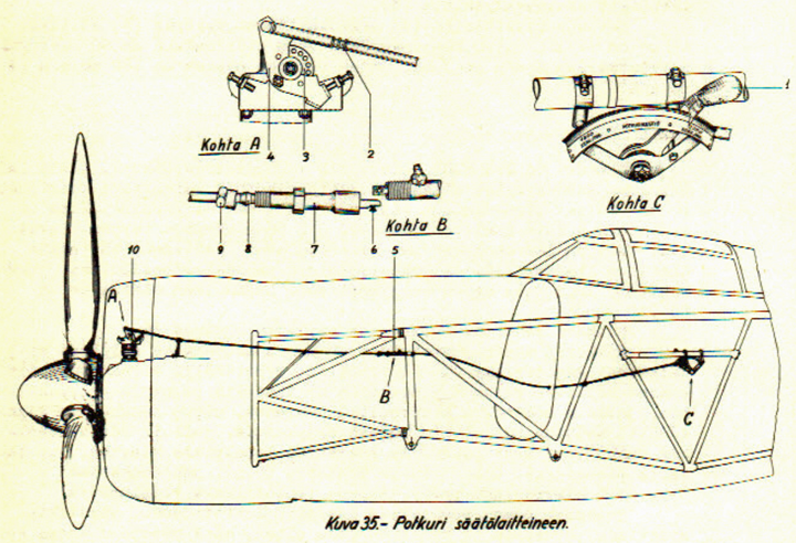
MY-14 got propeller control and throttle leversTorstai 29.6.2017 - Reino Myllymäki VL Myrsky II fighter has a VLS 8002 constant-speed propeller. According to name, the propeller keep the rotational speed by changin the blade pitch.
The object on the gear box is the constant-speed unit. Notice the quality of the leading edge of the NACA ring. Photo: The Finnish Aviation Museum. VLS 8002 in a propeller construction of the State Aircraft Factory. It has three wooden blades with Hamilton Standard 3 E 50 hub. The hub is not made by Hamilton: it is finished in Finland by using Swedish preform. The constant-speed unit is designed by Hamilton and it can change the blade pitch between 27 and 47 degrees.
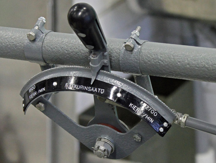
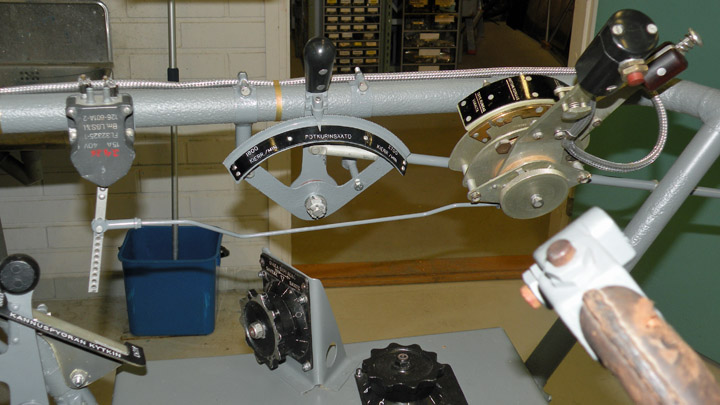
The blade pitch can be adjusted by a control lever in the cockpit. In front the blade pitch is decreasing and the rotational speed is increasing. In back vice versa. The lower pitch is used in the climbing and the higher pitch in the cruising. The propeller control lever of MY-14 was very corroded. The friction plates and knob were disappeared and the parts of the control levers of the MY-5 and the MY-5 had to be utilised. The steel parts were glass ball blasted and painted by Isotrol primer and paint. The duralumium parts were cleaned by oxalic acid. The new friction plates were lathed by using original Parkesin as a material. The Parkesin is trade mark of nitrocellulose called to "lusto" in Finland. In addition, the knob was lathed from black Parkesin and fixed by aluminum rivets. The original instruction plate of the control lever has preseved but in three parts. The material of the plate was Paxolin plate. Paxolin is fenol laminated paper. The paint was removed machanically and repainted by Miranol paint. The parts were glued together by epoxy resin and the result was fixed by aluminium rivets.
The casing pipe of the Teleflex wire of the propeller control system was cleaned by steel wool and some spacers' nuts were substituted by original parts. The steel casing pipes were so corroded that they had to be renewed. Since the engine is not yet installed, the Teleflex wire was not installed. In addition to that, the front part of the casing pipe system is still lacking. The throttle lever system consists of two levers. One controls the mixture and another is the essential throttle lever. There is a push-to-talk switch in the knob of the lever. In all, the throttle lever system is not a simple system since there are adjustable restrictors and a bar to enable the whole control range at the high altitude. All three throttle lever systems of the MY-5, the MY-9 and the MY-14 were in so poor condition that using an original spare part was a good idea. Unfortunately it was not complete. The throttle lever system was disassembled. The plywood friction plates were grinded until the system ran correctly. The steel parts were painted and a new knob were made. The push-to-talk switch was substituted by an original spare part. The wiring was renewed but the fastenind bands were original spares.
Finally, the levers were fixed. The result is excellent, isn't it? Histotical photo: The Finnish Aviation Museum. Other photos: The Finnish Air Force Museum. |
|
Avainsanat: aviation history, restoring, old aircraft, VL Myrsky II, MY-14 |
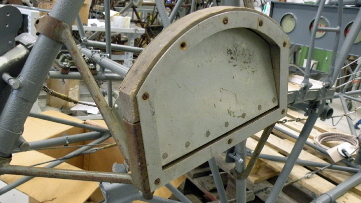
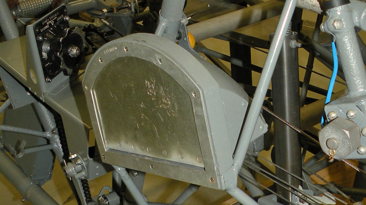
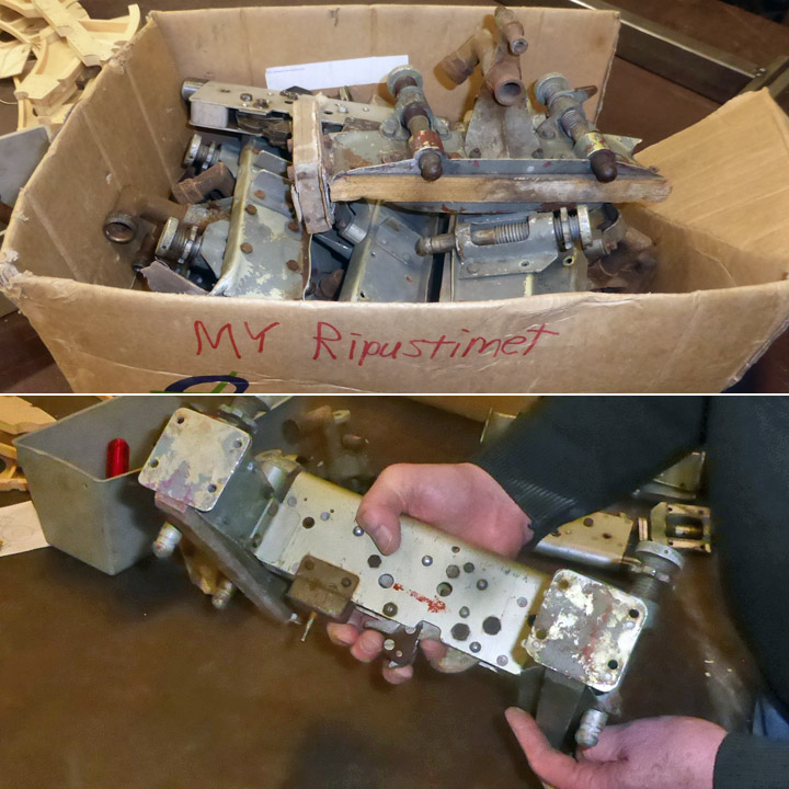
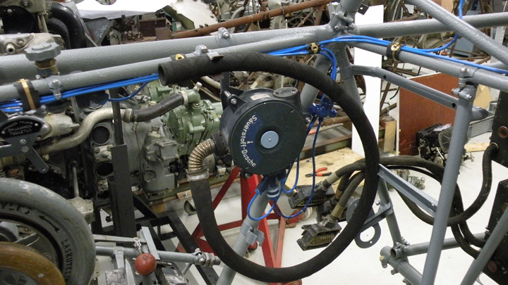
My-14 got something that she shouldn't haveTorstai 22.6.2017 - Reino Myllymäki According to the modification announcement dated late July 1944 at the State Aircraft Factory, the alarm buzzer of the landing gear should be substituted by the pilot light in VL Myrsky II. The maintenance instructions do not tell anything about the alarm buzzer. That is a warning system in order to warn when the engine runs idle and the landing gear is up. It was intented to avoid belly landings. The buzzer could be turned off by a switch. The alarm buzzer has disappeared but the bracket remained. According to that, the MY-14 had an alarm buzzer. It had not been changed to the pilot light during the repairs.
There were several alarm buzzers including brackets in the storages of the Finnish Air Force Museum. The best one has been restored for the MY-14. The orginial bracket was accepted but the mounting plate was renewed. The Siemens switch is an original spare part but the lacking press button was manufactured in the workshop. The alarm buzzer is located in the rear part of the cabin, front of the radio. Photos: The Finnish Air Force Museum. |
|
Avainsanat: aviation history, restoring, old aircraft, VL Myrsky II, MY-14 |
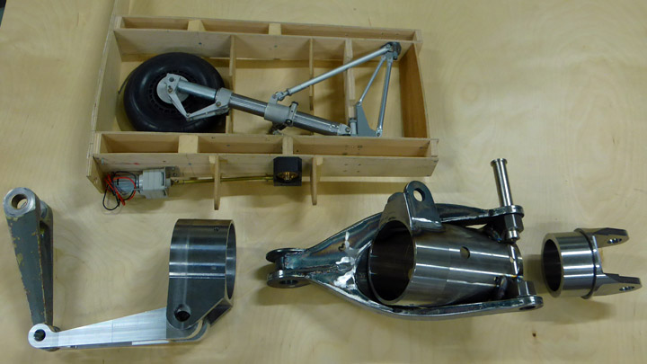
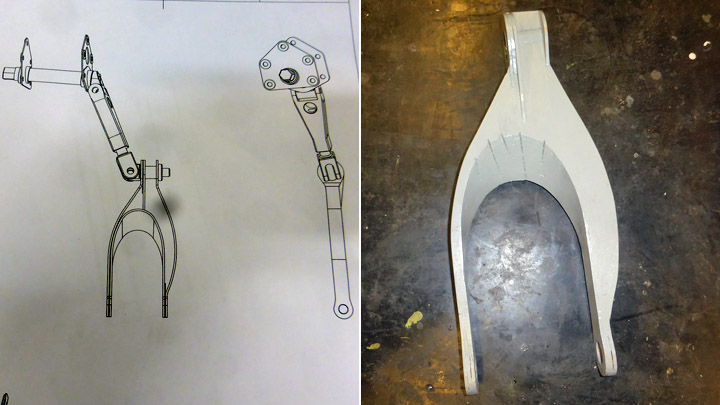
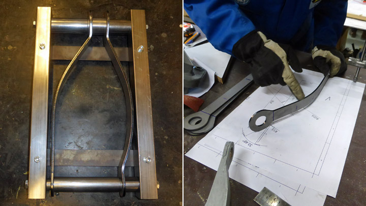
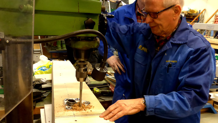
About the parts of the Myrsky landing-gear strutsTiistai 6.6.2017 - Member of Tuesday Club Though the test-wing under construction for the VL Myrsky (MY-14) by the Aviation Museum Society’s Tuesday Club is not yet ready for the installation of the main landing-gear parts of the landing-gear assembly have already been made and are ready to be installed. Unfortunately, only some original parts, such as wheels including brake mechanisms and parts for fastening the landing-gear assembly to the wing-spars, have been found. Thus, we need to have a number of the parts for the complicated landing-gear assembly manufactured. Luckily, we have most of the drawings needed for the manufacturing of the landing-gear parts available. Also, the landing-gear of the 1:4 scale Myrsky model made by our Myrsky-project manager Matti Patteri is proving most helpful. Patria Oy has taken the responsibility for manufacturing the oleo-struts. The Tuesday-Club’s Myrsky-project team has taken the responsibility for all other parts of the landing-gear. Thus, in addition to having the main responsibility for the wooden parts, the project team will also work on some metal-parts for the Myrsky.
The topmost object is the landing gear of 1:4 model of Myrsky manufactured by Mr. Matti Patteri. This far, we have already finished the lower and upper forks of the scissor-joint that is a part of landing-gear retraction mechanism at the lower end of the oleo-strut as well as the axle beam components attached to the wheel-hub. Also the lug-tube that will go on to the middle of the oleo-strut and to which the forks of the landing-gear retraction mechanism as well as the rear landing-gear support strut will be attached. The upper fastening fork that goes onto the top end of the oleo strut has already been made.
Matti Patteri has been responsible for the design and guidance for the manufacturing of the metal parts including the laser-cutting as well as for the making of the jigs needed for the welding-work. Welding-work has also been performed at the Vantaa Vocational College Varia. The machining of some of the small metal parts has been done by Elmer Oy. |
|
Avainsanat: aviation history, restoring, old aircraft, VL Myrsky II, MY-14 |
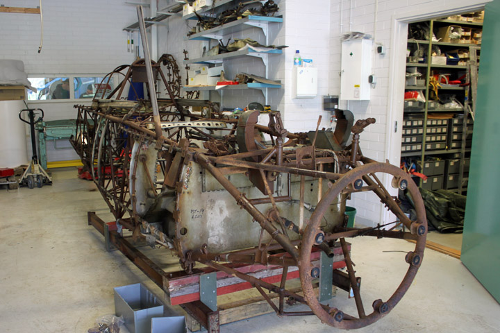
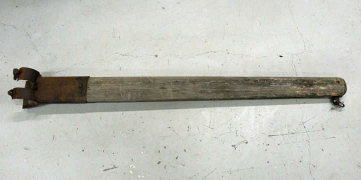
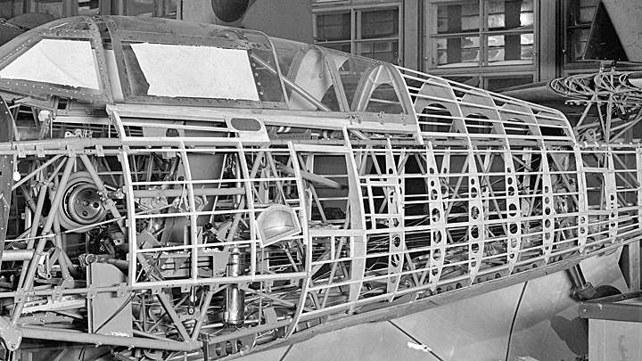
One original wooden part to MY-14Torstai 1.6.2017 - Reino Myllymäki The VL Myrsky II restoration project has three steel-tube fuselage framework (MY-5, MY-9 & MY-14). They have lain on the ground below an open sky at least 20 years. Therefore wooden parts have decayed and steel parts have corroded. The project has got ready for substitute all wooden parts by reproduction ones.
There is boarding step located below the rear side of the canopy in the left side of the fuselage. The boarding step has a small hatch in order to keep the fuselage streamlined when the step is not in use.
The boarding steps of MY-5, MY-9 and MY-14 were all very corroded and the hinges of hatches were stuck. Luckily, one unused original spare part has been found in the storages of the Finnish Air Force Museum. One supporting tube was broken and there is a hole in an aluminium box.
The steel structure, the hatch with hinges and the plywood frame have been taken from the unused spare. The lacking tube was taken from the step of MY-14. It was welded to the steel structure.
The aluminum box was taken from the step of the MY-5. The metallic parts were blasted by glass balls and painted. The dented aluminium parts of the box and the hatch were corrected. The original screws of the plywood frame and box were substituted by equivalent new screws. It seems that MY-14 will have at least one original wooden part: the plywood frame of the boarding step. Historical photo: The Finnish Aviation Museum. MY-9 photo: Reino Myllymäki. Other photos: The Finnish Air Force Museum. |
|
Avainsanat: aviation history, restoring, old aircraft, VL Myrsky II, MY-14 |
MY-14 got more equipmentKeskiviikko 24.5.2017 - Reino Myllymäki There is a metallic map box on the left hand side of the cockipit of the VL Myrsky II. Luckily we have an original part. The proper box is in a good condition but a little crooked and the leather strap was in poor condition.
The map box was blasted by glass balls, straightened, primed by Isotrol lacquer and painted to colour tone Ral 7045 (gray). The leather strap was renewed but the popper is original. The strap was riveted to the box. The box was fixed by renews bolts and screws to the cockpit.
There is a fresh air lever on the right side of the cockpit. The original was in a very poor condition. Luckily a quite complete original part was found from the storages of the Finnish Air Force Museum. Only the another fastening band was lacking.
The fresh air lever was blasted and painted. The help texts were renewed, too. The lacking fastening band was substituted by a repaired original part. The wire of the lever will be installed later. |
|
Avainsanat: aviation history, restoring, old aircraft, VL Myrsky II, MY-14 |
VL Myrsky has crank starterTorstai 18.5.2017 - Reino Myllymäki The Twin Wasp engine of the VL Myrsky II is started by an inertial starter. Normally, the starter is powered by an electric motor. When the starter has enough revs, the pilot pull the starter on and the engine will - hopefully - start. But the revs can be made by a crank starter, too. The extension rod of the crank starter is located to right side of the aircraft near the leading edge of the wing. The location of the joint of the extension rod and the crank starter handle is not easy to find in the photos. Most of the photos present the left side of the aircraft. And the camouflage painting is dark just there.
Left photo: Finnish Air Force Museum, right: Finnish Aviation Museum. When the aircraft has not coverings, the location is easier to find. The joint is supported by three tubes from three direction. The crank starter handle is located in the cockpit. It has place on the left side at the back of the tail wheel switch. The crank starter handle of the MY-14 has disappeared as well as MY-5´s and MY-9´s. The brackets have been spared. Luckily, an original crank starter handle of the VL Myrsky has been found from the storages of the Finnish Air Force Museum. Only cleaning was needed.
MY-14 got brackets from the MY-5 since they were in better condition. They were disassembled, blasted, painted and fixed. After that, the crank starter handle found an appropriate place. |
|
Avainsanat: aviation history, restoring, old aircraft, VL Myrsky II, MY-14 |
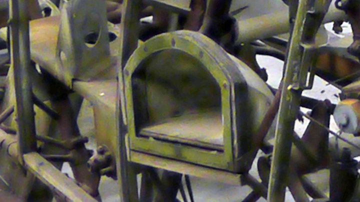
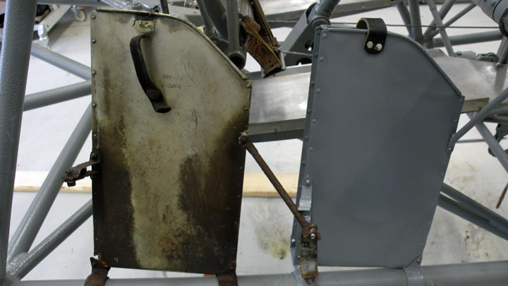
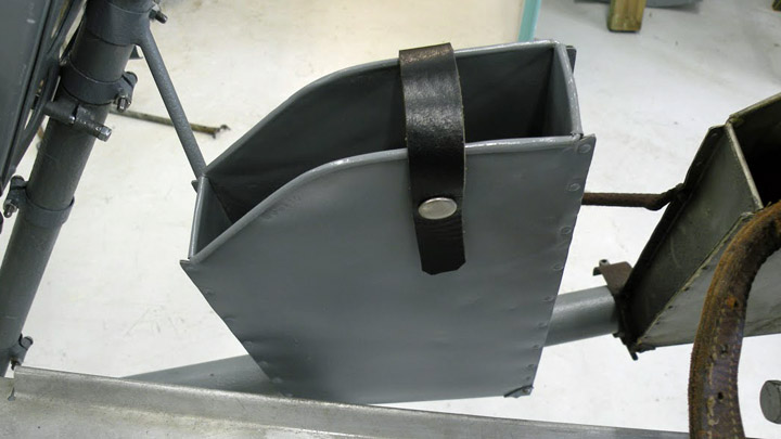
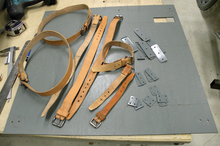
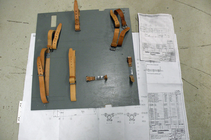
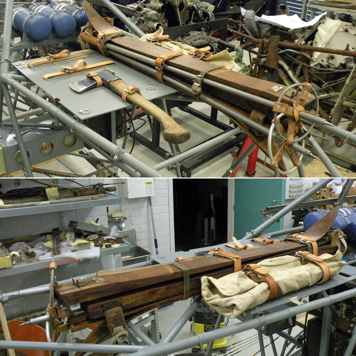
Emergency equipments to MY-14Maanantai 15.5.2017 - Reino Myllymäki VL Myrsky has the emergency equipment consist of a pairs of skiis, an axe, a K-ration pack and a toolkit. They are located after the cockpit and the oxygen bottles below the the canopy aft glazing. They were attached to the plywood plate by leather straps. The access to the emergency equipment bay was arranged by the glazing hatch.
The brackets of the plywood plate were existing in the all frames (MY-5, -9 and -14). Although the axe did not belong to the emergency equipment anymore, it had still the leather straps. Now the straps were disappeared except small parts between the plywood plate and mounting plates. All emergency equipments were disappeared.
The new plywood plate has been made according to the drawings. The brackets were blasted and painted. The screws were renewed.
The mounting plates of the leather straps were renewed. The leather straps were made according to the drawings and the preserved parts of the Fokker D.XXI (FR-137).
The leather straps were fixed to the plywood plate according to the drawings.
The pairs of skiis were restored and tared earlier. They were fixed to the plate. The axe was fixed tentatively since the axe and the toolkit did not belong to the emergency equipments during the wartime. The K-ration pack belonged but it has disappeared. The drawings of the K-ration pack were disappeared, too. The historical photo: The photo archive of the Finnish Aviation Museum. Other photos: The Finnish Air Force Museum. |
|
Avainsanat: aviation history, restoring, old aircraft, VL Myrsky II, MY-14 |
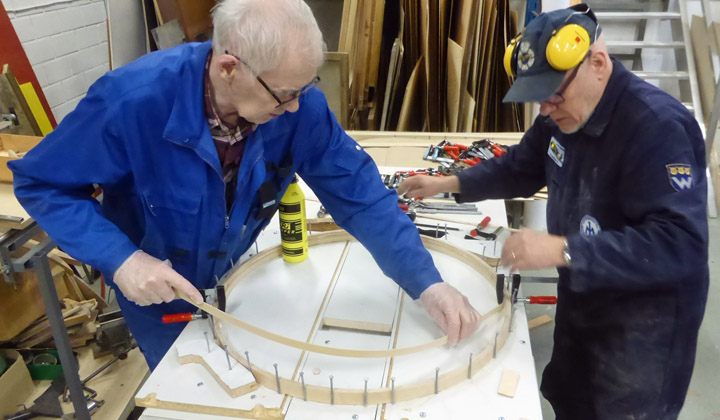
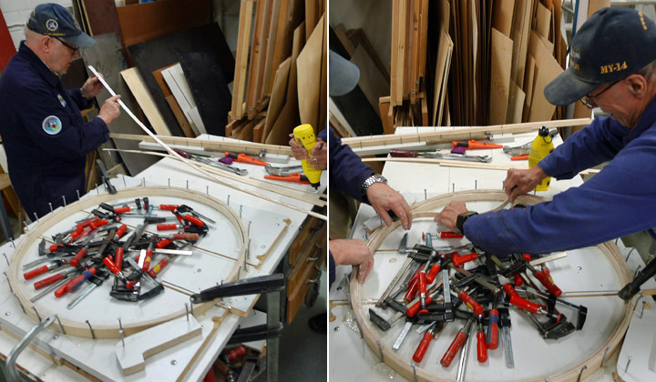
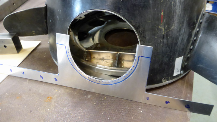
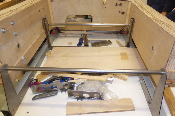
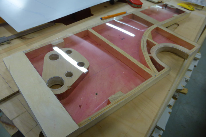
Wheel-bay cover fastening ring for VL Myrsky IILauantai 18.3.2017 - Member of Tuesday Club The landing-gear of the Myrsky retracts towards the fuselage with the struts and wheels retracting into bays between the main spars in the roots of the single, continuous wing.
On the top-side of the wing the wheel-bays are covered with slightly domed covers made of aluminium-plate. The covers are fastened with screws to a plywood ring forming the wheel-bay. Most of the wheel-bays, including their aluminium cover-plates remain hidden under the mid-fuselage covering the centre-part of the single wing, but a part of them are covered by streamlining-plates at the wing/fuselage joints.
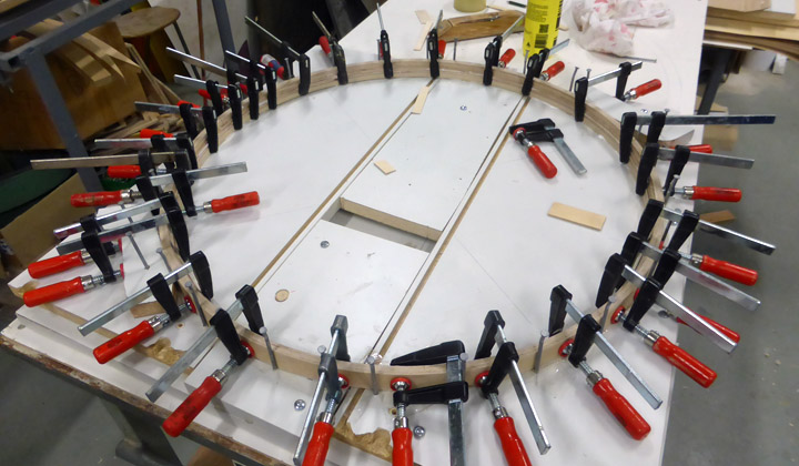
The aluminium-plate wheel-bay covers have already been made and now the making of the three needed cover-fastening rings are underway. One is needed for the test-assembly wing and two for the final wing that will be made for the MY-14.
The making of the fastening-rings begun by making a mould. As on the drawings, a circle with a diameter of 750 mm was drawn onto a strong wooden board. Then sturdy nail were nailed along the drawn line with a spacing of ca. 2 inches. The fastening-rings will now be made by laminating eight layers of 3 mm thick 30 mm high, long plywood strips against the nailed circle, thus forming a 25 mm thick fastening-ring.
The first plywood-layer was tightened against the nails and onto it three more layers were glued using Erikeeper plus adhesive intended for outdoors use. The four layers were pressed tightly together using clamps. When the adhesive had dried properly, the clamps were released and the next four layer were added using the same procedure.
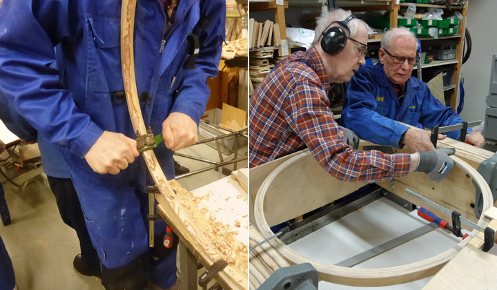
When the adhesive had dried the fastening-ring was removed from the mould and finished. It was then planed into a triangular cross-section with a top width of 25 mm. The other two rings will be made in the same way.
As the test-wing had been fitted into the assembly-jig and the part between the wing-spars had been assembled the test-fitting of the fastening-ring could be made. And it was a good fit. Also the aluminium cover-plate went into place nicely. The next step will be making and fitting the plywood landing-gear well walls in the wing. |
|
Avainsanat: aviation history, restoring, old aircraft, VL Myrsky II, MY-14 |
More than just building wing for VL Myrsky IILauantai 4.3.2017 - Member of Tuesday Club In the restauration of the VL Myrsky II (MY-14) the majority of the work done during the past couple of years has been on the wing. This might lead one to believe that the Tuesday Clubs part the whole project is only doing woodwork to make the wing. However, a lot of other types of work has also been done, as I have told you in earlier blog entries. This time I will cover some of the work on the following sub-assemblies; bomb-racks, the propeller-blade openings in the spinner and the landing-gear. Originally the Myrsky-fighter was not equipped with bomb-racks, but in 1944 a bomb-rack for a 50-100 kg bomb was fitted under each wing. These racks were also suitable for drop-tanks. For these there was a connector to connect the drop-tank to the planes fuel-system.
Fortunately parts for many racks have survived in the collections of various museums, so with some reconditioning done, we can fit the MY-14 with original racks. However, the racks found were partly disassembled, had broken parts, partly corroded or otherwise in need of reconditioning. So a selection of the best rack-parts were inspected, reconditioned and combined into complete racks to be fitted to the Myrsky´s wing in the Tuesday Club.
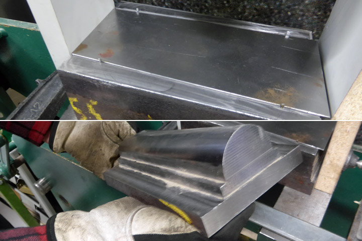
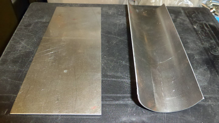
The spinner for the Myrsky has cut-outs for each propeller-blade and its regulator mechanism. At the base of the spinner the cut-outs are open so that the spinner can be fitted over the propeller hub and around the propeller-blades and fastened to the spinner’s back-plate.
On the spinner’s back-plate there is a protective sleeve made of aluminium that closes the back-part of the cut-out, thus creating a round cut-out hole and a closed back-edge on the spinner. No original sleeve has survived, so new ones have to be made. The missing spinner back-plate has already been made earlier in the Tuesday Club.
The making of the sleeves begun by cutting blanks out of aluminium sheet, according to the drawings. Then they were test-fitted to the openings. A wooden mould was made for the making of the profiled, bent edge of the cover-plate, and then the blank was fastened to the mould and beaten into shape. We still have to drill the holes needed for fastening the cover-plates to back-plate and then the cover-plates can be fit into position. The finishing work on the cover-plates is now ongoing.
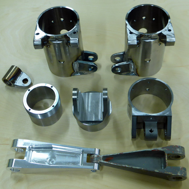
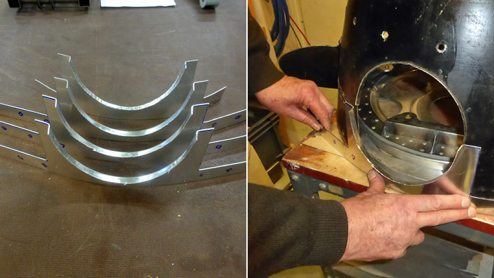
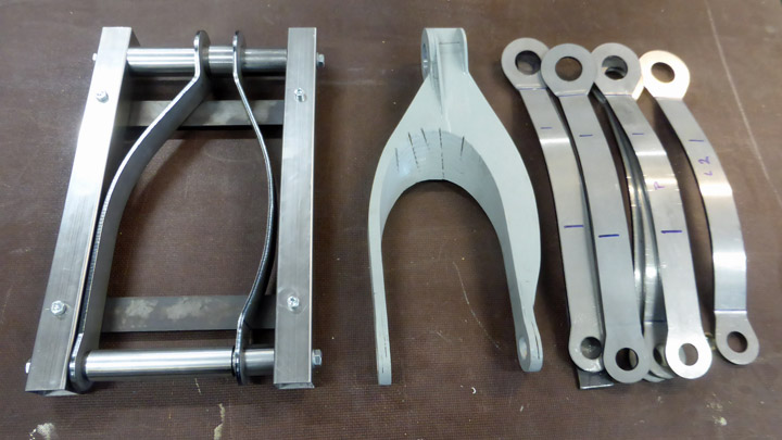
No complete Myrsky landing-gear has survived to be fitted to the MY-14. Thus most of the landing –gear has to be made. Fortunately original wheels have survived and can in due time be fitted to our Myrsky. The reconditioning of their hubs and brakes has been covered in earlier Myrsky blog-entries.
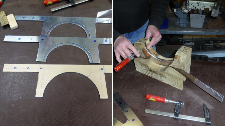
The Tuesday Club has neither the tools nor the skills necessary to make the needed new landing-gear oleo-struts. Patria, who is the major sponsor of the Myrsky restoration-project has taken the responsibility for getting them done. However, some landing-gear parts can be made by the Tuesday Club. Work on the landing-gear retraction-fork that connects to the oleo-strut is ongoing in the Tuesday Club. The hollow forks (one for each strut) consist of steel-ribs that are covered with steel-plates.
The work on the fork was started by making a full-size model to plans. In addition to this a metal jig was made for the assembly of the final forks. The wooden model makes interpreting the drawings easier and without a jig, the necessary dimensional precision of the retraction-fork cannot be achieved.
Work on the fork itself begun by cutting steel-plate blanks to measure to form the parts that will become the sides of the forks. Holes were drilled at both ends of the blanks after which they were bent to form and measure. Assembling the forks in the jig is ongoing. |
|
Avainsanat: aviation history, restoring, old aircraft, VL Myrsky II, MY-14 |
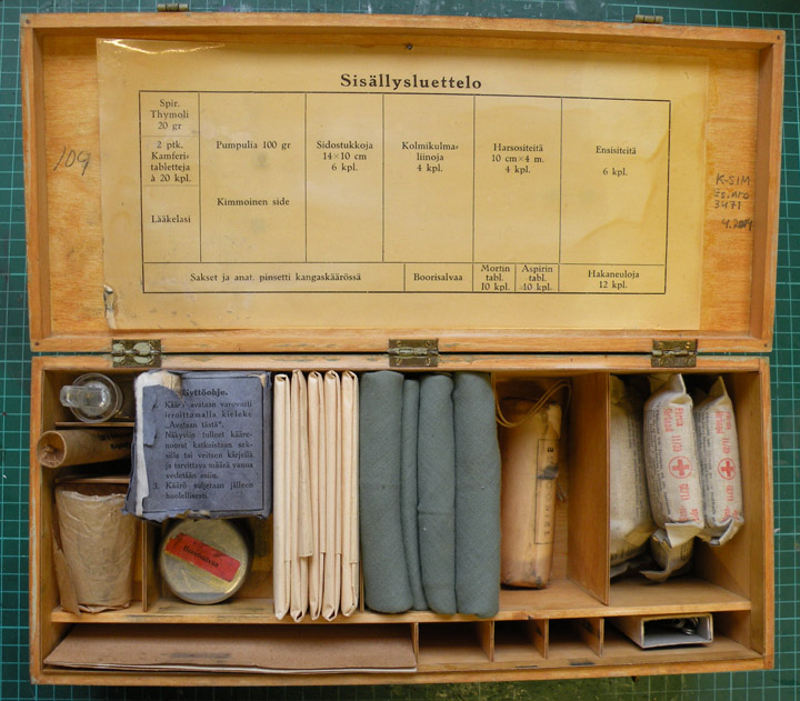
MY-14 got original medicine boxTorstai 16.2.2017 - Reino Myllymäki The medicine box of the VL Myrsky II fighter located outside of the cockpit in the rear fuselage. The box was behind a access panel in the left side of the fuselage.
The access panel of the medicine box located below the cockipt rear windows. The location was shown by red cross sign. It was not in exactly right place since the access panel was located under the national insignia. Between the access panel of the medicine box and a entry foothold of the cockpit there was one bigger access panel. The stand of the medicine box was manufactured from the metal plate by shop welding. The sides of the stand was lightened by holes. The box was fixed by leather straps. The straps were fixed to the stand by riveting. An original stand was found. It was restored by cleaning and painting. The medicine box is a aircraft part standardised by the State Aircraft Factory. VL Pyry and VL Myrsky had same box. MY-14 got the medicine box from Pyry.
The medicine box was complete except medicines. According to the index of the box, the box consisted of boracic ointment, morphine and aspirin and two bottles of camphor. None wartime pep pills were found and according to the index, pep pills did not belong to the content of the medicine box.
When MY-14 will be ready the medicine box will be in hiding behind the access panel. Several other interesting details will be in hiding, too. However, a "Demo-Myrsky" is planned to be assembled from a test wing, the fuselage of MY-5 as well as from the extra original parts and newly produced parts. The demo will be covered partly by plywood and partly by perspex. How it will implemented and how the inside structures and detalis will be seen is not clear yet. |
|
Avainsanat: aviation history, restoring, old aircraft, VL Myrsky II, MY-14 |
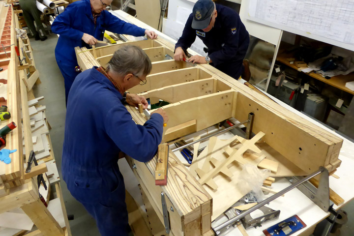
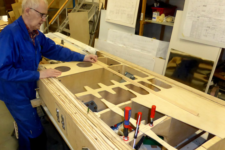
Assembling VL Myrsky (MY-14) test-wing in jig started.Tiistai 14.2.2017 - Member of Tuesday Club The MY-14 project group decided to build a test-wing of ca. 2.5 m length, measured from the wing-root. This will be done to ensure that the fitting of equipment and fittings that are fastened to the wing spars, including drilling holes for necessary fasteners can be done properly and also to pinpoint possible flaws in the building of the wing.
During the early weeks of this year we were able to finish the front- and rear spars of the test-wing as well as the drilled holes for the metal parts lead-throughs. Also all the wing-ribs have been finished. Thus, the test-assembling could be started. The assembly work of the test-wing, as well as that of the final wing, will be done in a precision jig. A separate jig was made for the assembly of the test-wing. Using this, we can make sure that the placement and alignment of the spars related to each other will be spot-on. This is a must for us to be able to assemble the wing in strict accordance to shape and measures of the drawings.
The assembly of the test-wing was begun by fastening the front- and rear spars in the jig. After this some parts of the landing-gear actuating mechanism were fitted to the drilled-through. The next steps was to start fitting the enclosed wing-ribs in-between the spars.
At this point the benefit of the test-assembling became evident, as problems showed that the drawings were partly insufficient. Not an earthquake of challenges, but some additional head-scratching was needed before work could continue on the test-wing.
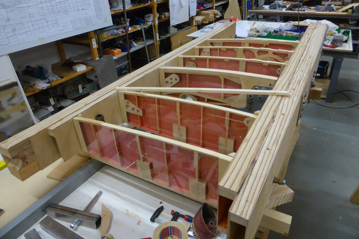
Now the wing-ribs between the spars are glued into their correct positions and the metal parts that attach to the wing-spars are fitted. Covering the top-side of the wing between the spars is ongoing. Assembling the leading- and trailing edges of the wing will start only after all internal structures between the spars have been made and installed.
The test-wing will not be disassembled after the tests, but instead it will become a museum exhibit. It will be used to show the visitors the construction of the WW II Myrsky-fighters wooden wing. For this purpose the top-side of the test-wing will be partly plywood-covered and partly covered with a clear polycarbonate sheet. The inter-spar wing-ribs will be plywood-covered on one side with the other side covered with clear polycarbonate sheet to show their construction.
Parallel to the work on the wing-spars for the test-wing, work on the spars for the final wing has moved forward. The front and rear parts of both wing-spars will soon be ready to be glued together so that they both form box-spars. As this wing will be made as a left and a right wing that will be bolted together with the joint strengthened with steel-plates, instead of the one-piece wing of the original Myrsky –fighter, holes for the assembly bolts must be drilled in the spars. Assembly work on the final wing will take place only after the test wing has been finished and properly tested. |
|
Avainsanat: aviation history, restoring, old aircraft, VL Myrsky II, MY-14 |
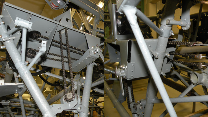
MY-14's tail repairs, part eightPerjantai 10.2.2017 - Reino Myllymäki The chains and cables for rudder, elevator and aileron trims of MY-14 were lacking except some very rusty chain pieces. So, the chains and cabled had to be manufactured acoording to the designs and original parts.
The used chain proved original material since the stamp was same than in orginal parts. The wire clips were original material used in the State Aircraft Factory but not exactly same.
The feed-throughs were existed but abrasion covers were lacking. They were made from "lusto" according to the designs. "Lusto" is an old polymere, nitrocellulose, called also to Parkesine.
The bearing bracket of the rudder trim and the traction wheel of the elevator trim were in the restorable condition. They were disassembled and repaired. The aluminium wire coils were lacking and the new ones were made by lathing. All parts were assemled and the entity was tested. It is working! |
|
Avainsanat: aviation history, restoring, old aircraft, VL Myrsky II, MY-14 |
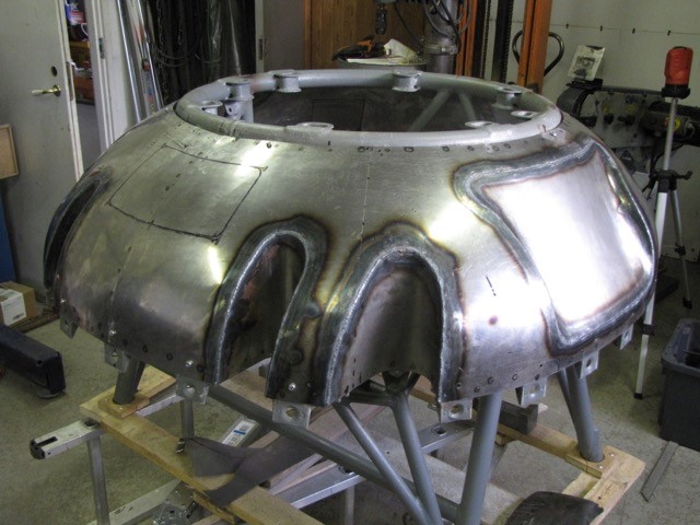
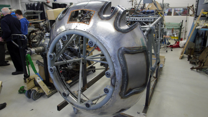
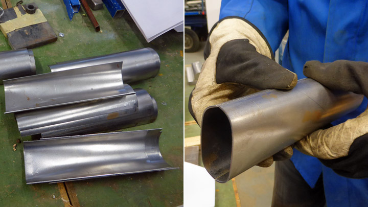
Work on the exhausts of MY-14 ongoingSunnuntai 29.1.2017 - Member of Tuesday Club The original engine planned to be used on the VL Myrsky was the British Bristol Taurus. Because of WW II this did not happen. Instead, the American Pratt & Whitney R-1830 two-row radial engine was selected, almost the same version as on the Douglas DC-3. Myrskyn MY-14 - entisöintiprojektia varten on käytössämme DC-3 koneessa ollut Twin Wasp -moottori. Koska moottori on ollut DC-3 koneessa, se ei ilman muutoksia sovi Myrskyyn asennetavaksi. Yksi merkittävä muutoksen kohde koskee moottorin pakoputkia.
The Twin Wasp with the exhaust collector of DC-3 in left picture and the Twin Wasp of VL Myrsky II with oval pipes in right picture. On the DC-3´s Twin Wasp the exhausts from each cylinder is connected to a single exhaust gas collector from which there is a single exit pipe. On the Myrsky a different solution was implemented – The exhaust from each cylinder was gathered to be expelled through five oval exhaust pipes on top of each other on both sides of the engine under the NACA cowling ending at the back-part of the cowling. At the end of each 10 round exhaust pipes 200 mm long, tapered nozzles were welded. At the weld the nozzles had a diameter of 60 mm but they were tapered towards their end, ending as a 28mm X 60 mm rectangles. A smaller final cross-section was used to increase the speed of the exhaust gases and thus creating some added thrust.
The exhaust system that is to be built during the restauration will be a copy of the original one. At the moment the single pipes from each cylinder, forming a veritable “snake-pit” are being formed into shape by a partner contractor at Samet Oy. The nozzles are being made by the Tuesday-Club.
They are being made from 28 rectangular parts cut out from sheet-metal. To form them into the requires shape the club made the necessary male and female mould parts used to shape the flat sheet-metal parts In a hydraulic press.
After being pressed the edges to be welded were cleaned and chamfered for welding. The assembly, welding and fitting of the exhaust-system to the Twin-Wasp engine will be done by Patria Oyj. |
|
Avainsanat: aviation history, restoring, old aircraft, VL Myrsky II, MY-14 |
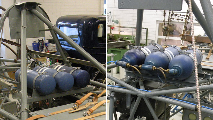
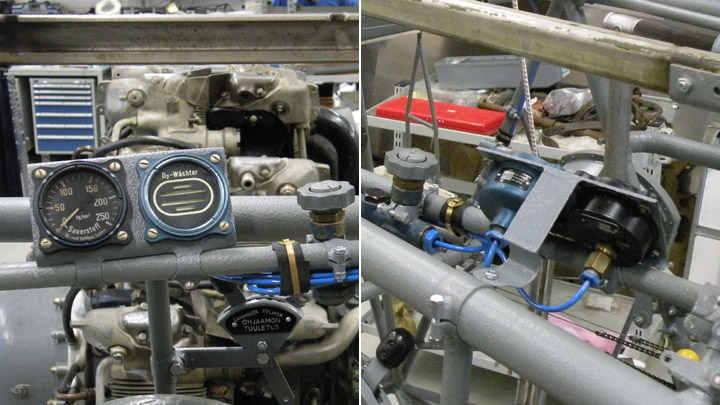
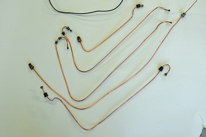
Oxygen system for MY-14Perjantai 27.1.2017 - Reino Myllymäki The oxygen bottles, controls, taps and meters of MY-9 and MY-14 were disappeared but the brackets, adapters, the remains of the oxygen pipes as well as the plate of the pressure and flow meters and controls were remaining. The original oxygen pipes were broken off and therefore they were useless.
The oxygen bottles were found from the Hallinportti Aviation Museum and they have been in VL Myrsky fighter according to the imprints of fastening bands. The other parts of the oxygen system were found from the storages of the museums. Therefore it was possible to assemble the proper oxygen system of VL Myrsky fighter for MY-14 from original parts. Only the oxygen pipes had to be renewed.
The best brackets were chosen in order to be restored. The steel and aluminium bands were blasted by glass balls and the bolts were renewed. The abrasion covers of the fastening bands were renewed. According to the design documents they should be made from leather. However, the imprints on the bottles showed that they were made from canvas fabric. Therefore canvas was used in the restoration.
The bottles and the parts of the oxygen system were cleanded and covered by Renaissance wax. The pipes were made from new copper pipe and the fastening screws were renewed. Othewise the system was assembled from original parts. The normal solder paste was used in the solder joints instead of a hard solder.
The fastening band of the rubber oxygen tube was taken from the MY-9. It was straightened, basted by glass balls, painted by Isotrol stripping laquer and paint finish. A padding made from leather was fastened inside of the band. Photos: Finnish Air Force Museum. |
|
Avainsanat: aviation history, restoring, old aircraft, VL Myrsky II, MY-14 |
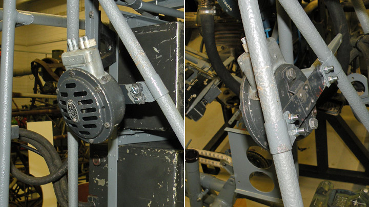
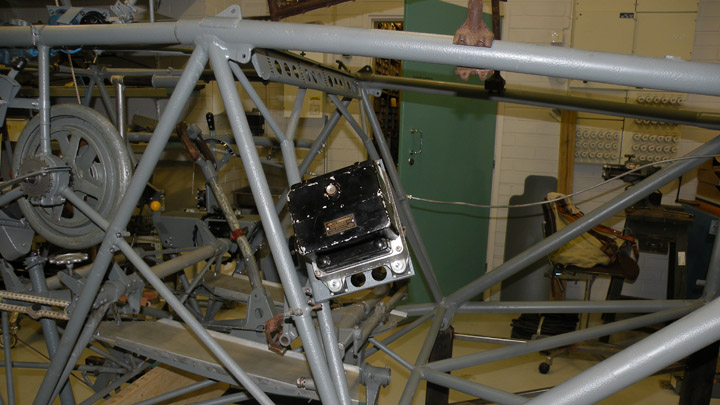
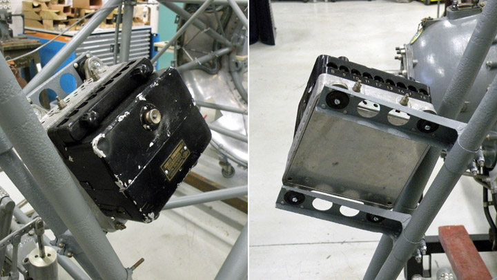
MY-14 got voltage regulatorKeskiviikko 25.1.2017 - Reino Myllymäki VL Myrsky II had a Russian voltage regulator located at the right corner in the front of the cockipit. However, the regulator of the MY-14 has disappeared. The brackets remained but they were corroded and bent. The sprung rubbers were destroyed and the filling sleeves were disappeared.
A proper voltage regulator (RKK GS 1000) was fortunately found from the storages of the Finnis Air Force Museum. It was cleanded outside and inside and covered by Renaissance vax.
The brackets were fixed, blasted by glass balls and painted. The bolts and sprung rubbers were renewed and the used rubbers were probably from MiG fighters. They seems to be copied from Britishs ones. Needed filling sleeves have been made from duraluminium by lathe work. Photos: Finnish Air Force Museum. |
|
Avainsanat: aviation history, restoring, old aircraft, VL Myrsky II, MY-14 |
Ilmailumuseot.fi - Aviationmuseums.fi