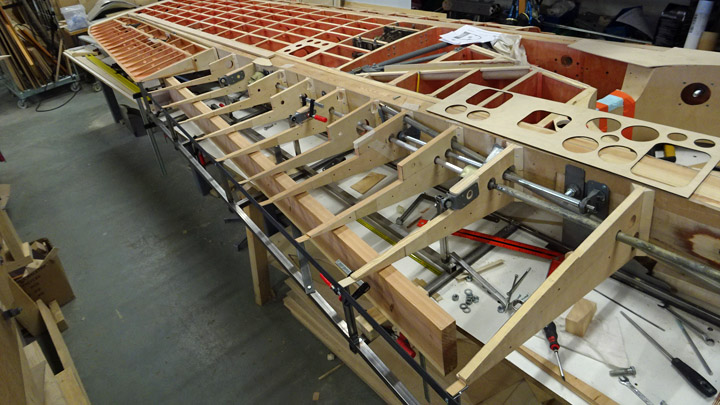
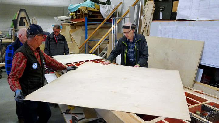
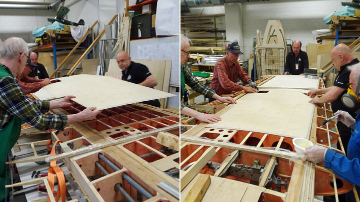
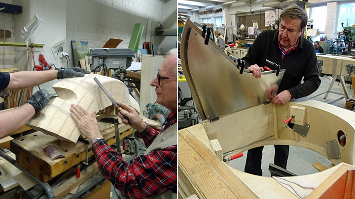
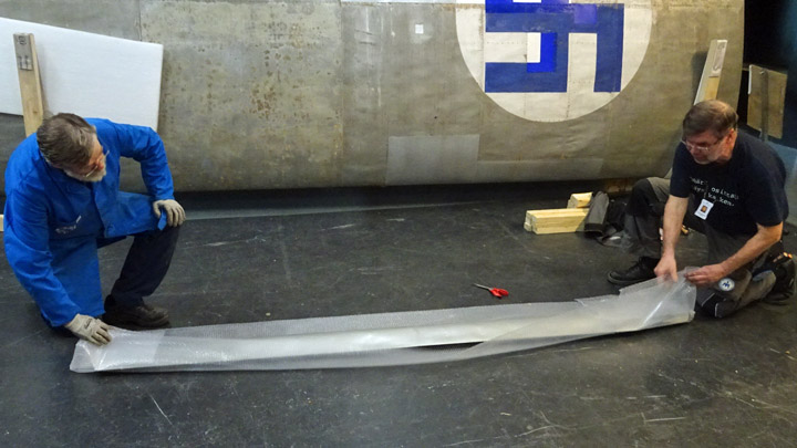
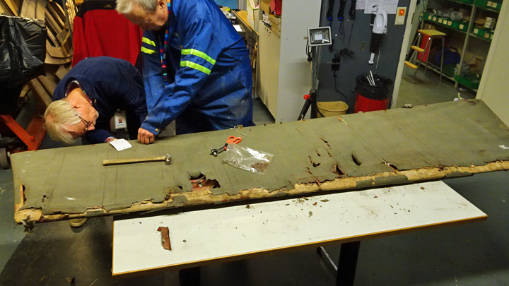
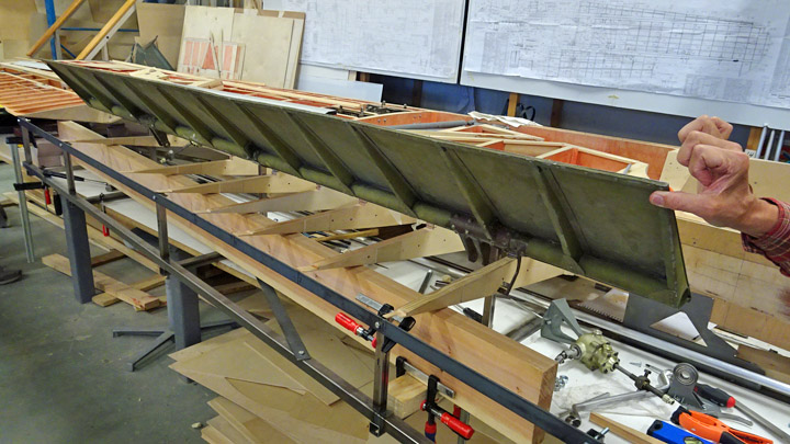
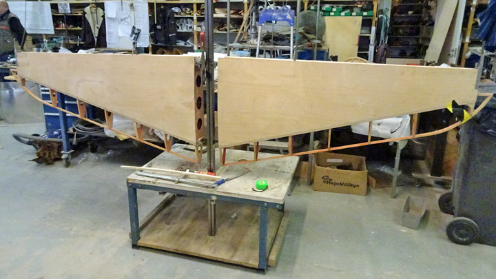
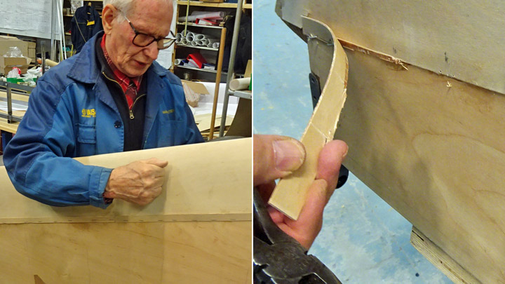
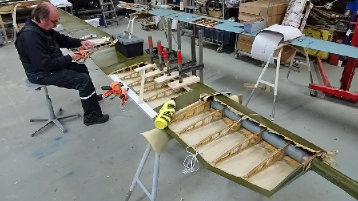
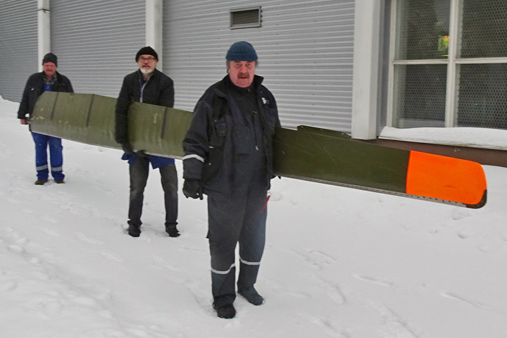
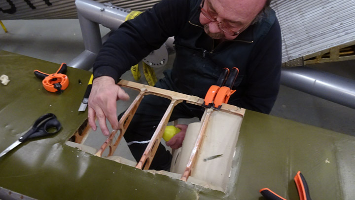
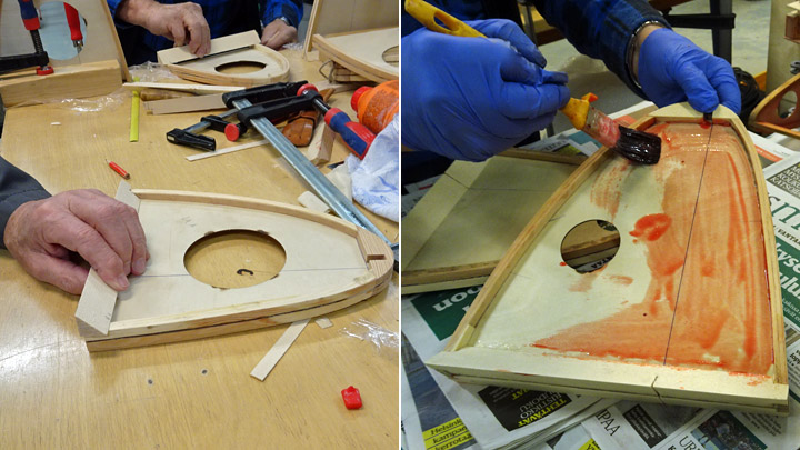
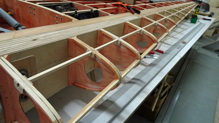
Flap niche on Myrsky's starboard wingSunnuntai 23.6.2019 - Member of Tuesday Club The assembly of Myrsky’s starboard wing has been going on for a couple of months. The ribs of the trailing edge have been installed up to the trailing edge strip. Also the operating mechanisms for the aileron, flap and landing gear have been installed through the holes in the ribs. At this point the Tuesday Club team could start covering the flap niche with plywood. When the flap is up / closed, it is pressed into this niche in the wing’s trailing edge. There is a notch in the trailing edge ribs, forming the perimeter of the niche.
The rest of Myrsky’s wing is a wooden structure but the flaps are split flap type plate flaps, made of duraluminium. When the flaps are up / closed and pressed into the niche under the wing, the flap is a part of the wing’s lower surface. When the flap is down / open, it turns down pushed by operation bars and angle gearboxes. The flap doesn’t move down and back as the flaps on modern passenger airplanes do.
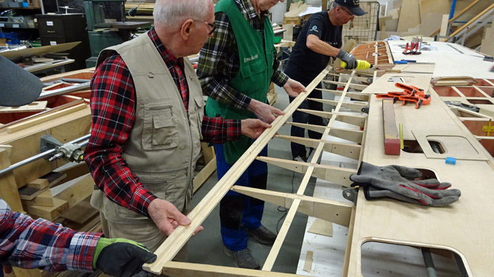
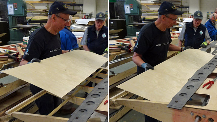
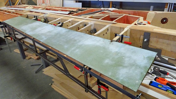
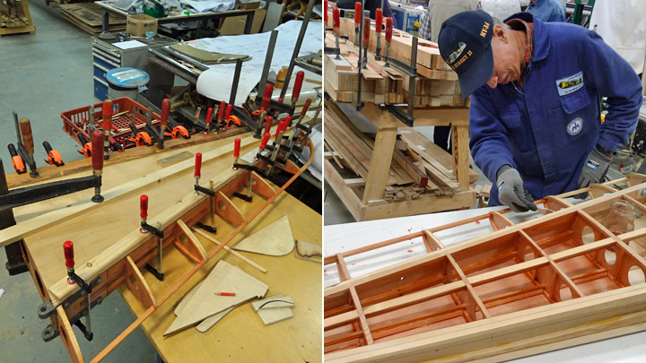
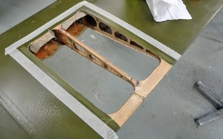
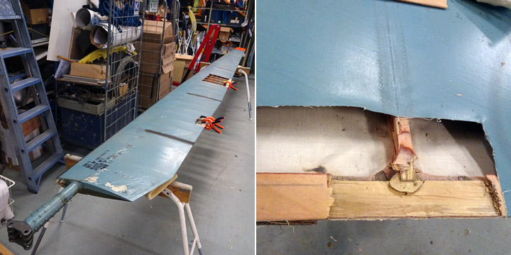
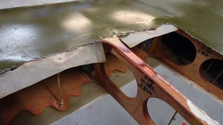
The starboard wing’s flap cavity work was started by covering the front wall, 70 mm high, with 1.2 mm thick plywood. The next phase was the upper side of the niche which is as wide as the flap. Fortunately the starboard wing lay upside down, i.e. the lower side up. Fastening the plywood against the trailing edge ribs was much easier than it would have been if the wing were the right way up.
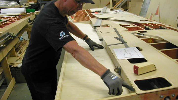
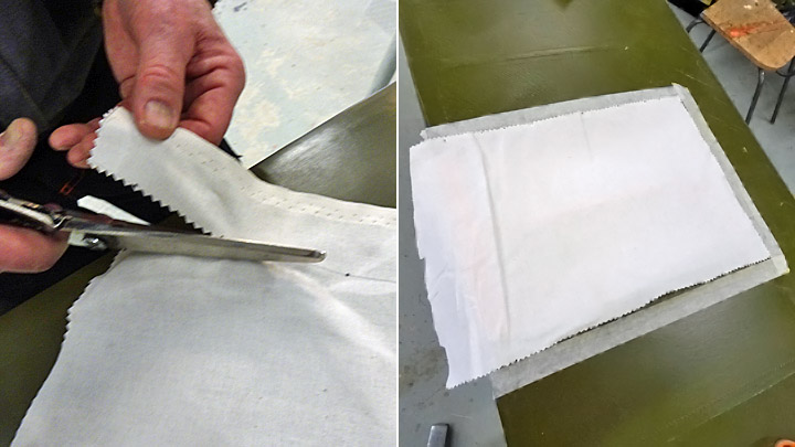
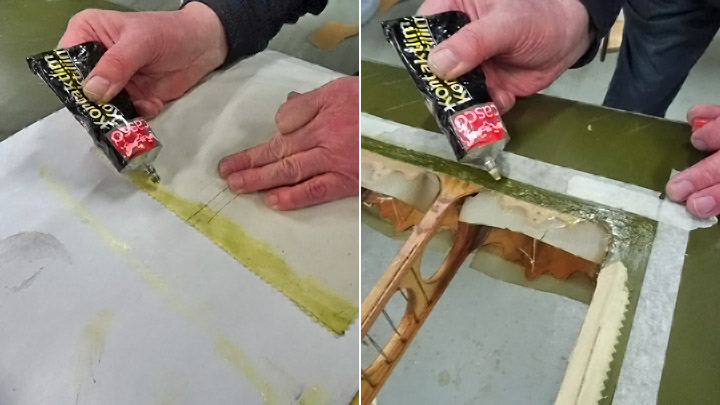
The flap niche will be covered with two sheets of plywood, connected in a lap joint. Two pieces of plywood were cut from 1,2 mm thick sheet of plywood, matching the dimensions of the niche. The joining edges of the sheets were beveled for the lap joint. The sheets were placed on the ribs, making sure that they settle properly against the ribs and the sides and can be glued into place.
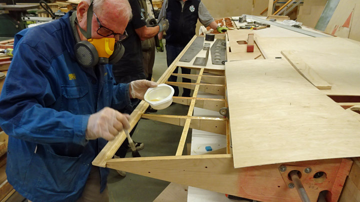
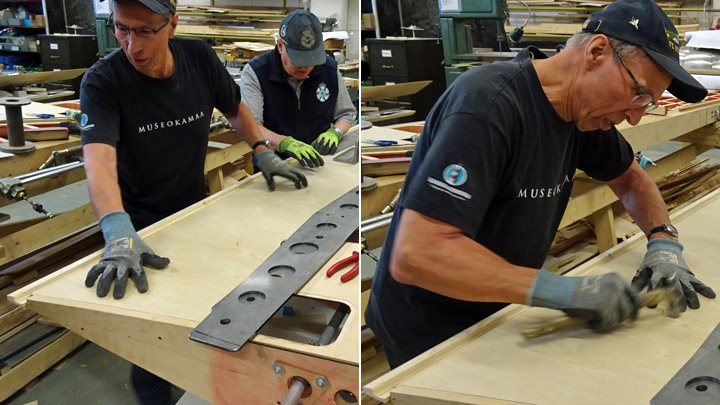
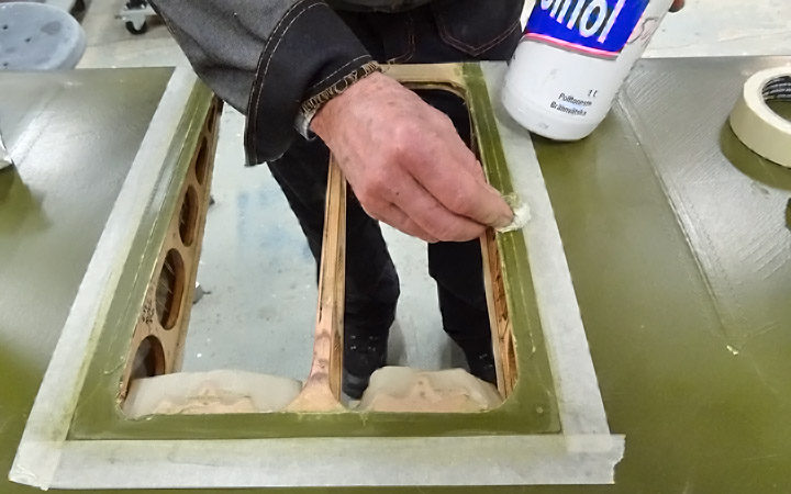
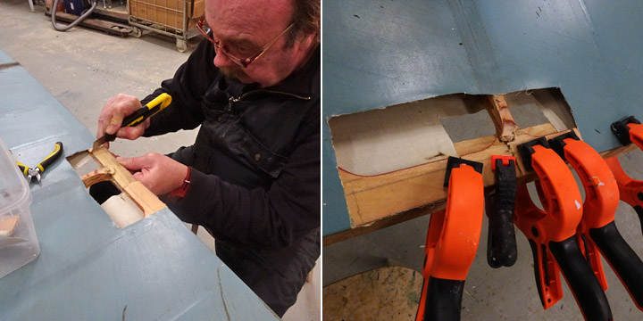
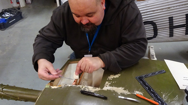
When everything was ready, the plywood sheet towards the wingtip was glued first and then the sheet towards the wing root. Two-component epoxy glue with cellulose fibre was used. The glue was spread with a brush on the ribs, on the battens between the ribs, trailing edge batten and the front and end battens of the flap niche.
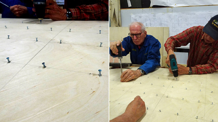
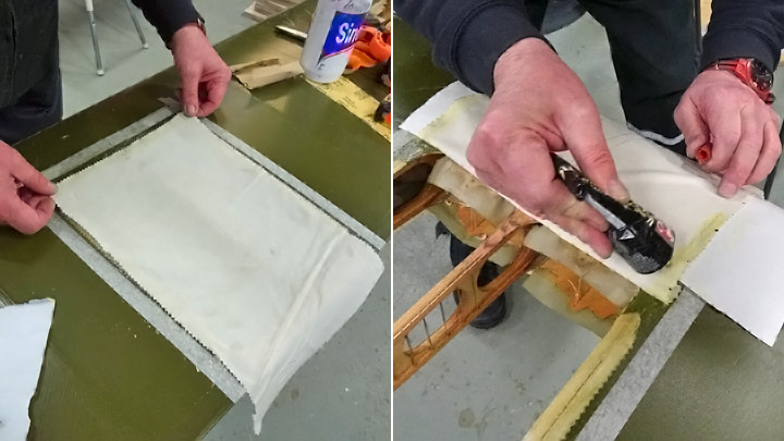
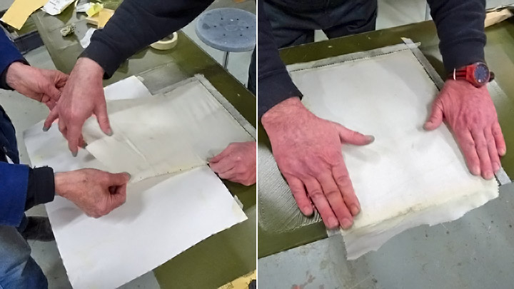
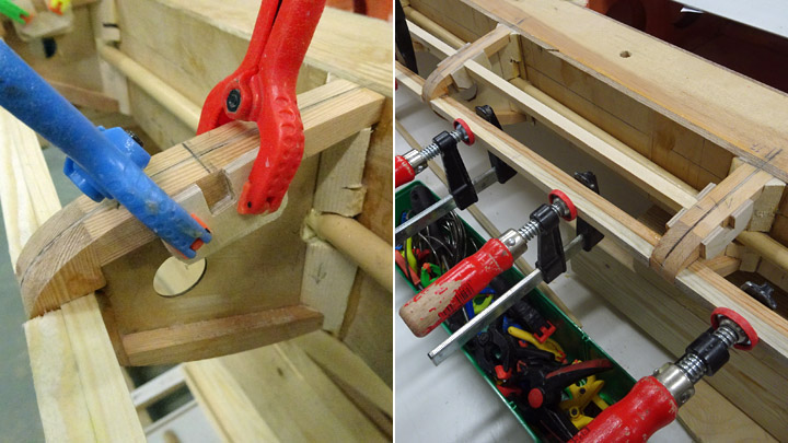
When the glue had been spread, the plywood sheets were pressed against the ribs and locked into place with aa couple of nails. Then heavy weights were placed on top of the sheets to press the glued surfaces together.
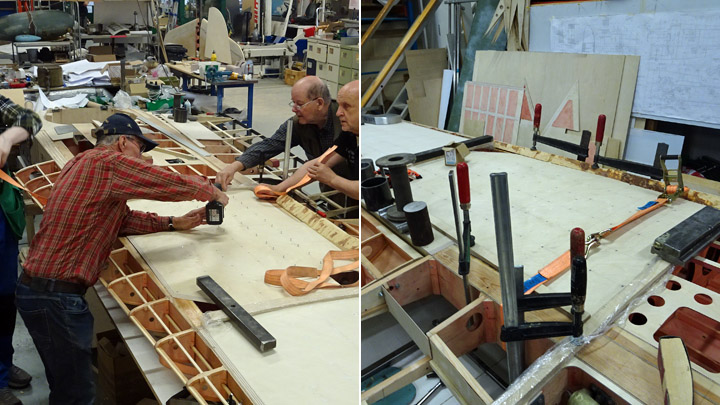
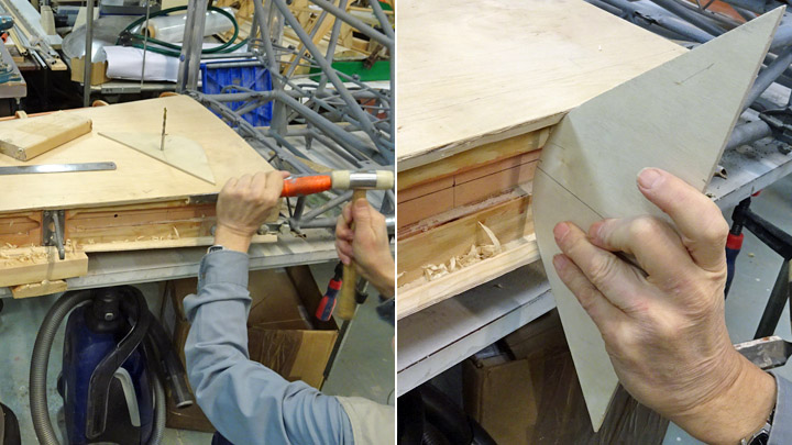
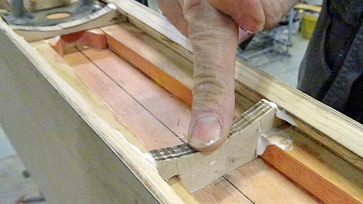
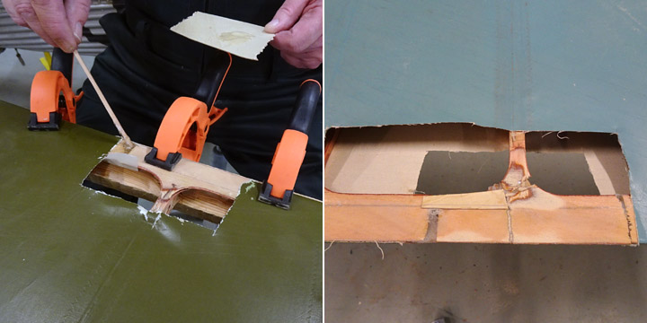
When the glue had dreid a triangular wooden batten was added to support the seam of the front wall and the roof plywood sheets.
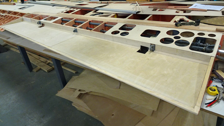
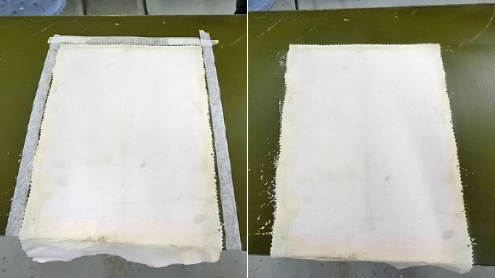
Now the niche of the starboard flap had been covered. Photos: Lassi Karivalo. Translation from Finnish to English: Erja Reinikainen. |
|
Avainsanat: aviation history, restoring, old aircraft, VL Myrsky II, MY-14 |
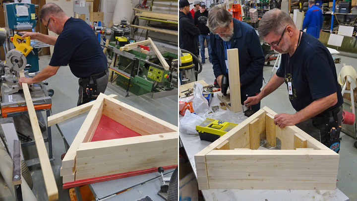
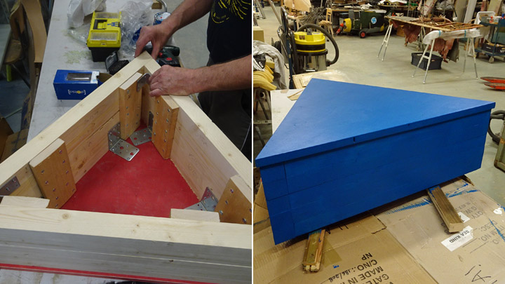
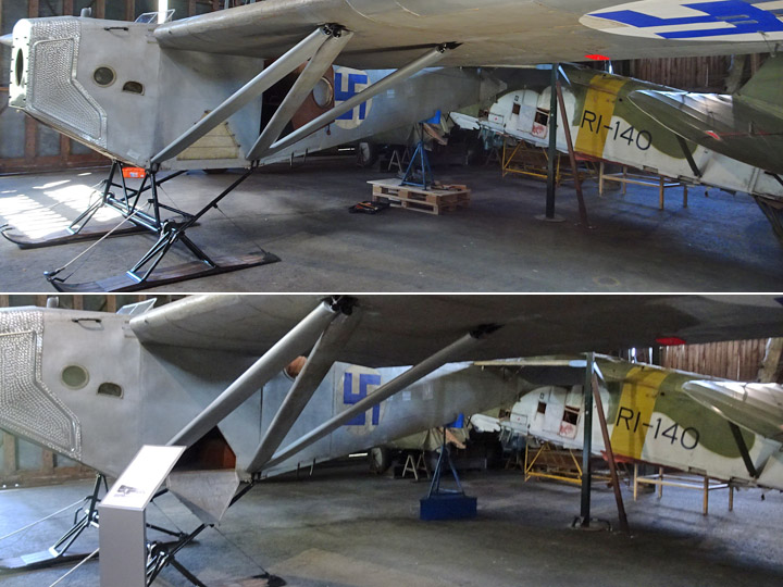
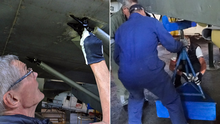
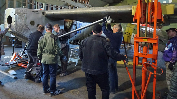
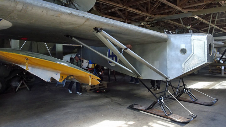
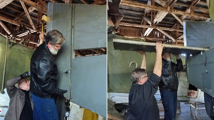
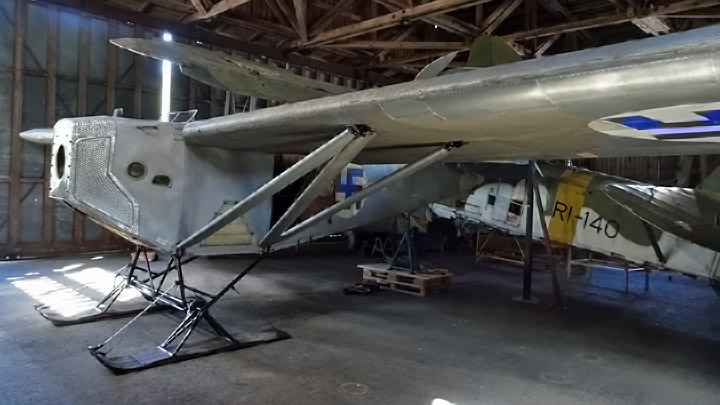
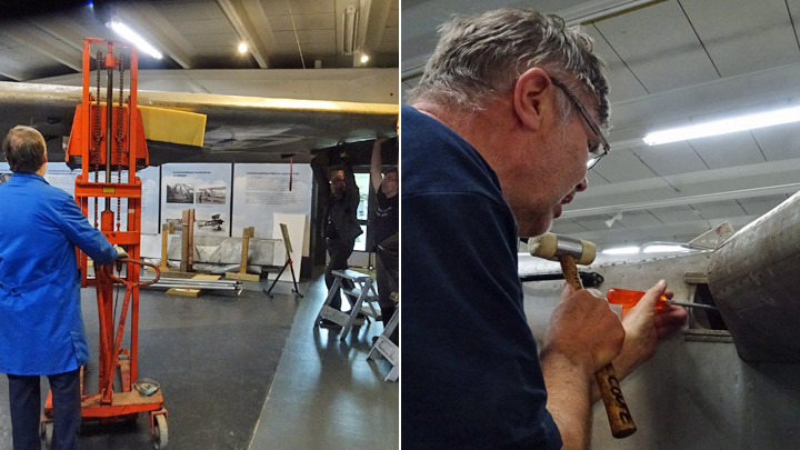
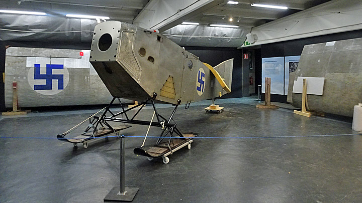
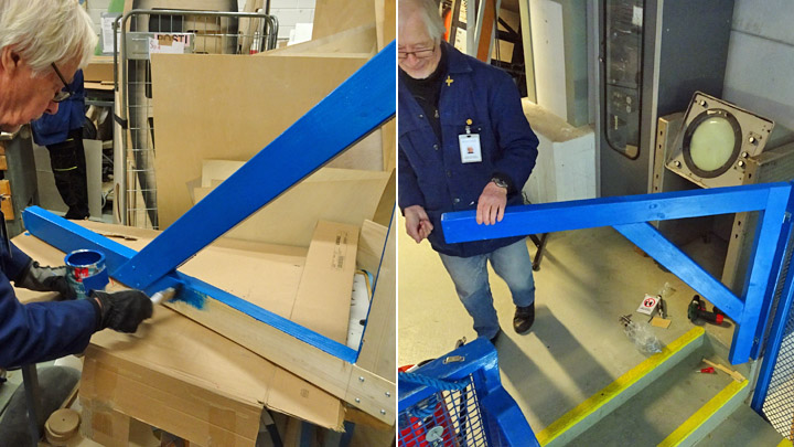
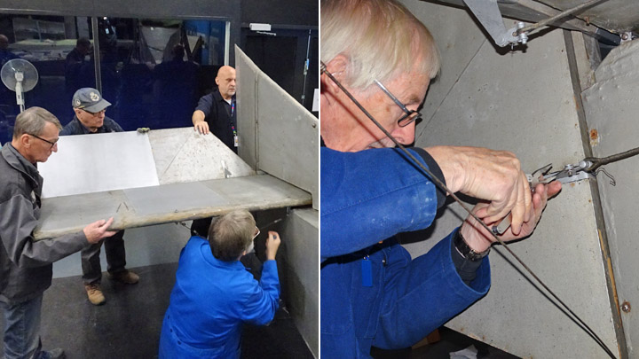
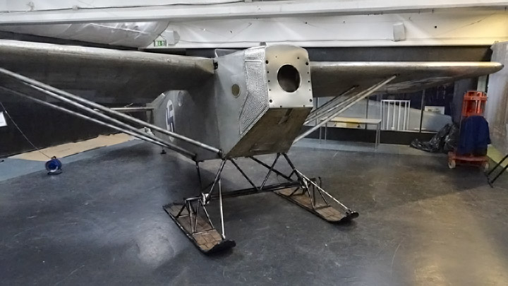
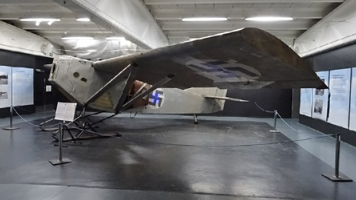
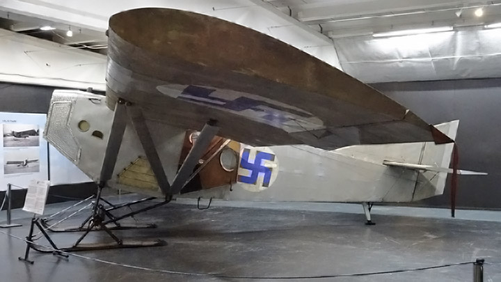
Final assembly work on Kurki at VesivehmaaMaanantai 17.6.2019 - Member of Tuesday Club The I.V.L.K.1 Kurki airplane, manufactured in 1927 at the Finnish Air Force Airplane Factory, was assembled and placed on display at the Päijänne-Tavastia Aviation Museum on May 15th, after three years of restoration work. Some minor details still had to be finished, such as adding the protecting lacquer on the wing struts, wing bolts and some bolts on the tail part. Also the covers for the wing spar attachment bolts had to be added in the upper corners of the cabin. The Tuesday Club members also decided to build a nice platform to support the metal tripod under Kurki’s tail. The improvised platform had consisted of two cargo pallets.
Suitable timber was bought for the platform. It was decided that the platform would be triangular to match the tripod under Kurki’s tail. The sides of the platform were built from 50x50 planed timber and the top plate was sawed from blockboard. The platform was built so that the parts were fastened from the inside, using concealed fixing, and the outer surfaces were nice and smooth. The platform was painted blue to match the colour of the metal tripod supporting the tail.
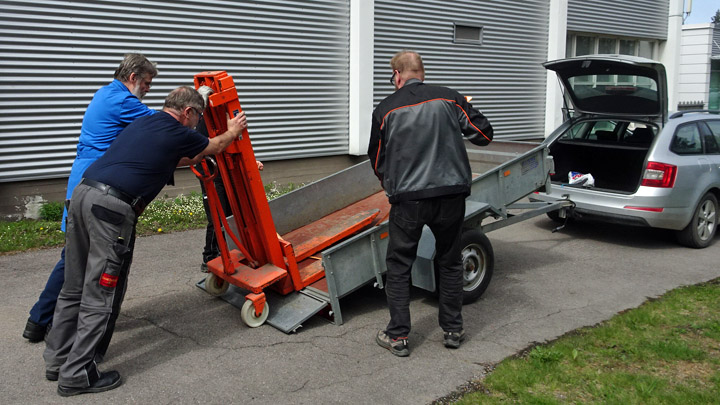
On Monday June 10th a group of Tuesday Club members drove to Vesivehmaa with the platform, some paint and screws, detergent and cloths. The team carried also the last one of the six metal shelves the Tuesday Club had assembled for the Päijänne-Tavastia Aviation Museum.
In Vesivehmaa the new platform was installed first. Kurki’s tail was lifted with a stacker so that the metal support could be unfastened, and the pallets moved aside. After this the triangular platform was placed under Kurki and the metal tripod was assembled on top. Kurki’s tail was lowered back on the tripod, which looked much better on the blue platform than on the cargo pallets.
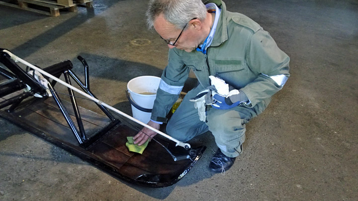
When the Kurki was back on its place, the team could carry on with other work. Some protected on the bolt heads and nuts, using rust-protective black or silver Isotrol lacquer, others fastened protective covers in the cabin and the rest of the team washed Kurki’s ski surfaces (which were dirty after the move and assembly work).
When all the planned work had been completed, Lahti Ilmasilta invited the team to have coffee and buns in the Vesivehmaa Airport cafeteria. The team was happy and ready to meet new challenges…. Photos: Lassi Karivalo. Translation from Finnish to English: Erja Reinikainen. |
|
Avainsanat: aviation history, restoring, old aircraft, I.V.L. K.1 Kurki |
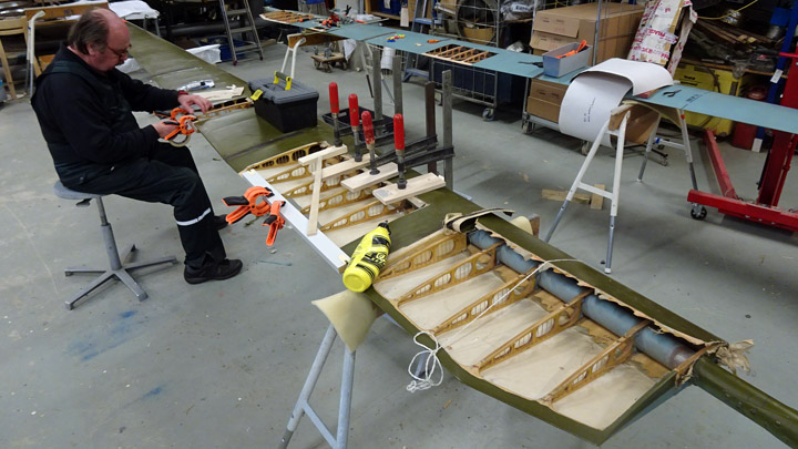
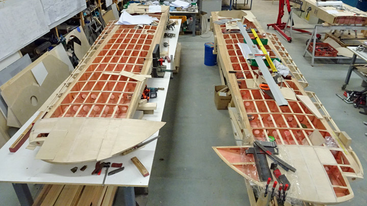
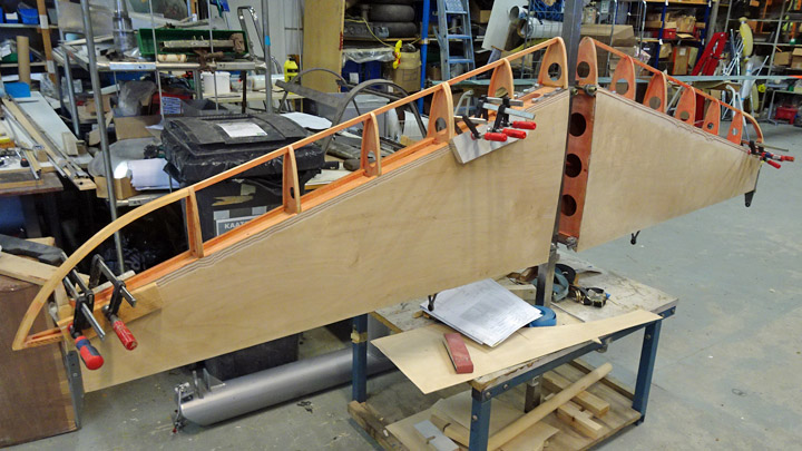
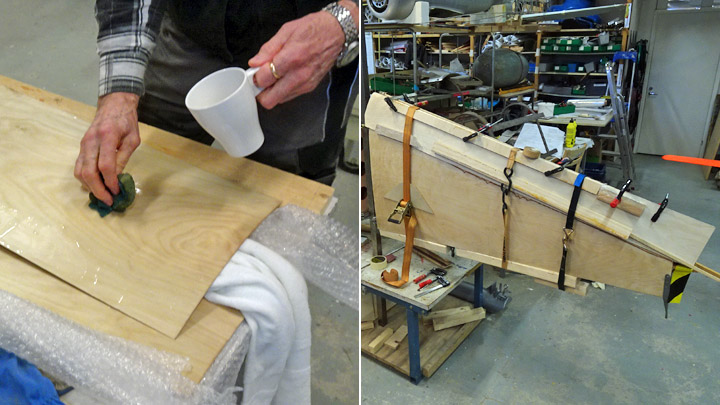
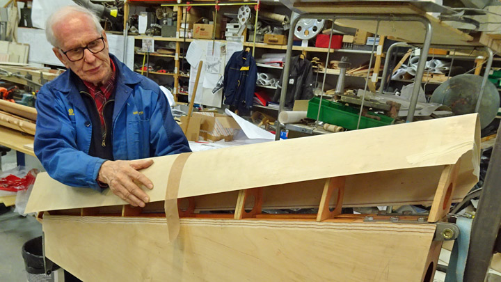
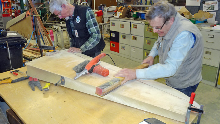
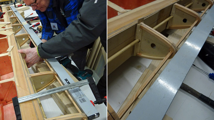
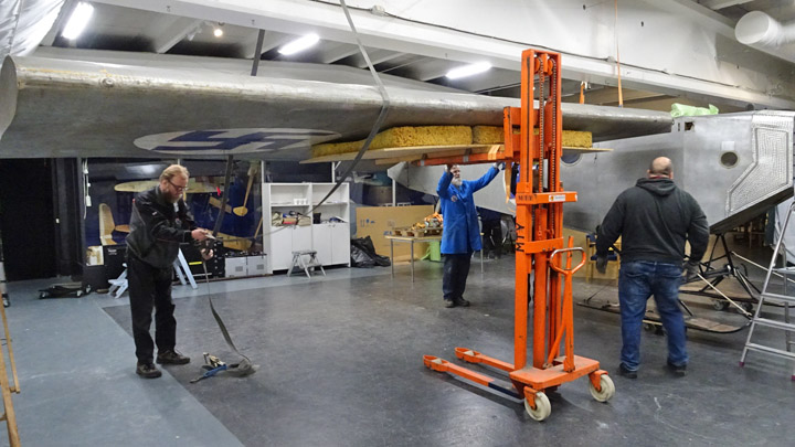
Lover side of Myrsky's starboard wing is coveredTiistai 11.6.2019 - Member of Tuesday Club The Tuesday Club continues its work during the summer. The work concentrates on the covering of the starboard wing’s lower side between the wing spars. The wing tip has already been covered and one sheet of plywood towards the root of the wing. The covering work continued by gluing a third sheet of plywood in place. The covering of the whole lower side of the wing is possible when all the equipment and operation mechanisms inside the wing have been installed (such as the fastening and rejecting mechanisms of the auxiliary fuel tank). The upper side of the wing has already been covered earlier.
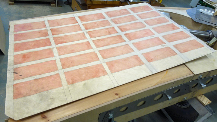
The original Myrsky wing plywood sheet had been cut from plywood board at a 45-degree angle, i.e. diagonally compared to the veneer layers. In ordinary thin plywood the bending strength and stiffness depend on the direction of the surface veneer, whereas diagonally cut plywood is equally stiff in both directions. However, cutting plywood sheets diagonally wastes material compared to cutting in the direction of the veneers. The restoration team decided to cut the plywood sheets diagonally for the Myrsky (MY-14), as they had originally been.
The work on the third sheet of plywood on the lower side of Myrsky’s starboard wing was started by placing a 3mm thick sheet of plywood on the wing area to be covered. The required piece was marked so that it can be cut diagonally. When the piece had been cut, its lower side was protected against moisture using lacquer tinted red. The areas to be glued were not lacquered.
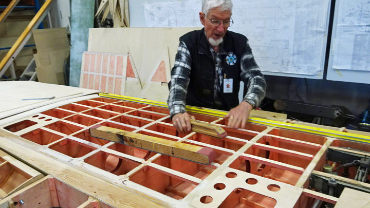
Some finalizing work was needed before gluing the plywood. The supporting battens between the wing spars were honed exactly into the same level so that there won’t be any dents or bumps in the plywood surface. Holes were drilled into the plywood so that the gluing can be secured with screws on the supporting battens on the wing surface.
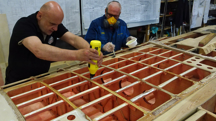
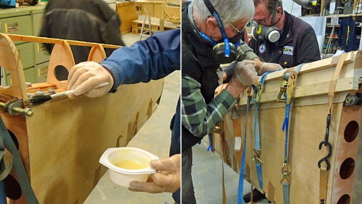
When all the preparations had been made, glue was spread on the front and rear spars, on the ribs and on the battens between the ribs. Epoxy glue with additional cellulose fibers was used on the spars and Erikeeper Plus wood glue on the ribs and battens.
The sheet of plywood was lifted above the wing and pressed against the glue. The correct position was checked and then the plywood sheet was secured in place, using a nail at the corner of the sheet. The screws were added to fasten the plywood sheet on the battens between the ribs. A cordless screwdriver was used, but the work was finalized using a manual screwdriver.
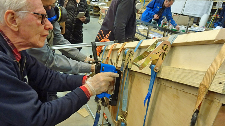
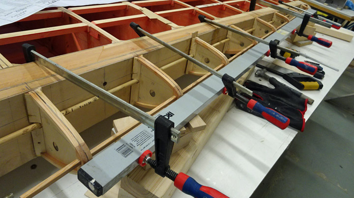
Cargo straps and strips of wood were used to press the plywood against the glued surfaces. Also clamps and metal weights were used to make sure that the edges of the plywood sheet press tightly against the glued surfaces. Now the third sheet of plywood on the starboard wing had been installed. Photos: Lassi Karivalo. Translation from Finnish to English: Erja Reinikainen. |
|
Avainsanat: aviation history, restoring, old aircraft, VL Myrsky II, MY-14 |
Tuesday Club goes on summer break - but not quiteKeskiviikko 29.5.2019 - Member of Tuesday Club The Tuesday Club’s spring season, filled with work, ended on May 28th. The activities will start again on August 13th. The main work items during the spring season have been the restoration of VL Myrsky II (MY-14), the final phases in restoring the I.V.L.K.1 Kurki and returning it to Vesivehmaa and the repair work on helicopter SM-1’s (HK-1) broken rotor blades. The new project, started in late spring, was the restoration work of the training plane Caudron C.59. In addition to the actual restoration projects, the Tuesday Club team has been involved in many other useful activities.
Building Myrsky’s wings was the most demanding of Tuesday Club’s work items this spring. Now the work is at the phase where the covering of the lower side of Myrsky’s starboard wing is on the way. Before that the equipment inside the wing has been installed, the ribs on the trailing edge have been attached on the rear spar and, most importantly, the operation bars for the aileron, spoiler and landing gear have been assembled through the trailing edge ribs. The team is getting ready to assemble the trailing edge ribs on the port wing. Building the wing has involved also making dozens of inspection, maintenance and operation hatches on the wing and making the hatches for the wheel wells. Myrsky’s horizontal and vertical stabilizers have been covered. Bending the aluminum sheets to form the upper part of the engine’s NACA-ring was a demanding task.
The title of this blog lets you know that, in spite of the summer break, the Tuesday Club team is busy in the restoration space of the Finnish Aviation Museum. The Myrsky-project will continue during the summer, maybe with just a short break. The team is aiming to have the Myrsky MY-14 ready by 2021, at the latest.
In May the Tuesday Club’s three years of work on the IVLK1 Kurki came to an end when the restoration work was completed, and the plane was returned to the Päijänne-Tavastia Aviation Museum in Vesivehmaa. The Tuesday Club Team was delighted to see Kurki on display in the museum hall. To fit the whole plane there was a little challenging and a matter of inches, but now it is there for the visitors to see.
Two broken rotor blades of the SM-1/Mil Mi-1 helicopter (HK-1) have been under repair since the beginning of this year. The damages in the blade structures have been repaired. The damaged areas in the fabric covering were dismantled and they have been covered with new fabric. Now the new covering is waiting for the treatment with shrinking dope and painting.
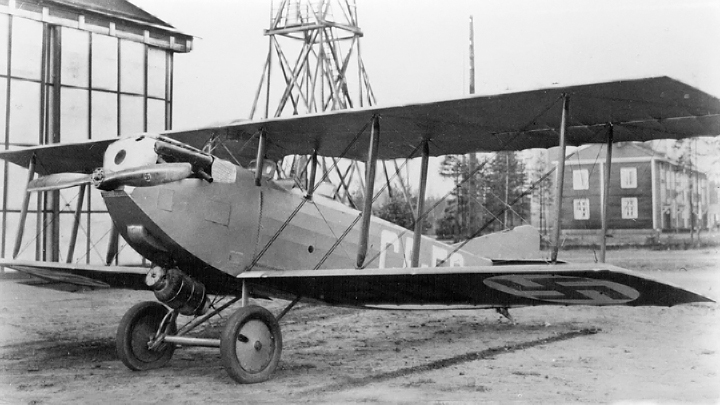
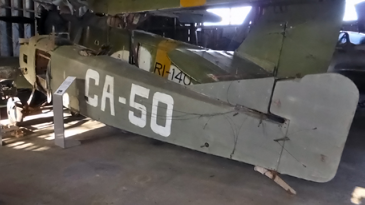
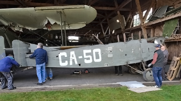
The new work item started in late spring is the restoration and repair work of the damaged Caudron C.59 training plane CA-50, which was used by the Finnish Air Force in the 1920’s. The work will take about three years and all damages will be repaired and the intact surfaces and structures will be conserved. The work was started at the horizontal stabilizer and elevators.
Photo: Juha Veijalainen
In addition to the restoration and repair projects of museum airplanes, the Tuesday Club has also been working on many other things. The Hawk Experience Center was improved by adding six metal cupboards and several hooks for cargo straps. Two passenger airplane cabin service trolleys were fixed to be used at the Experience Center. Six metal shelves were assembled for the Päijänne-Tavastia Aviation Museum, to be used in the storage containers outside the museum.
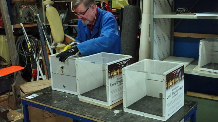
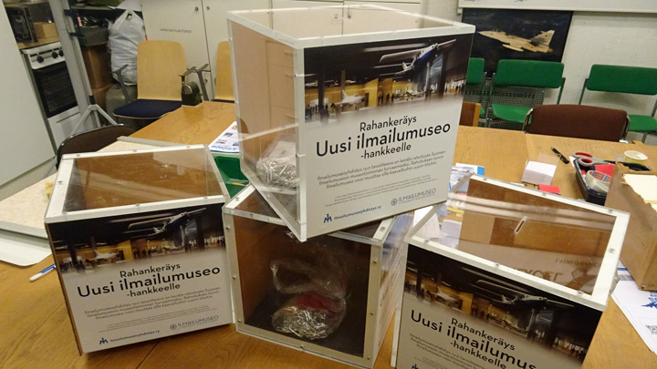
In addition to all this, the Tuesday Club team built six money collection boxes for the New Aviation Museum fund raising campaign of the Finnish Aviation Museum. Photos: Lassi Karivalo except if separately otherwise mentioned. Translation from Finnish to English: Erja Reinikainen. |
|
Avainsanat: aviation history, restoring, old aircraft, Tuesday Club |
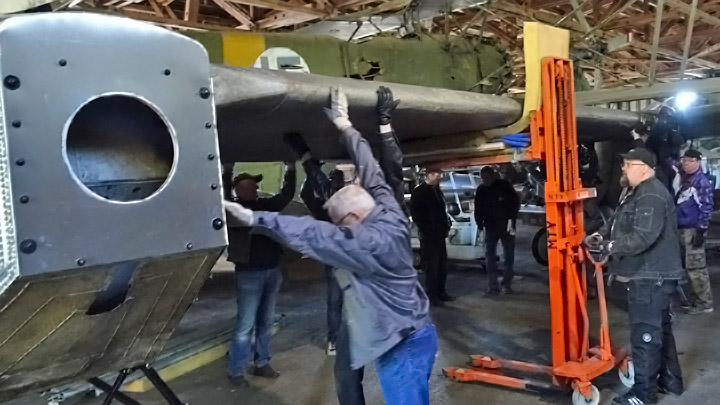
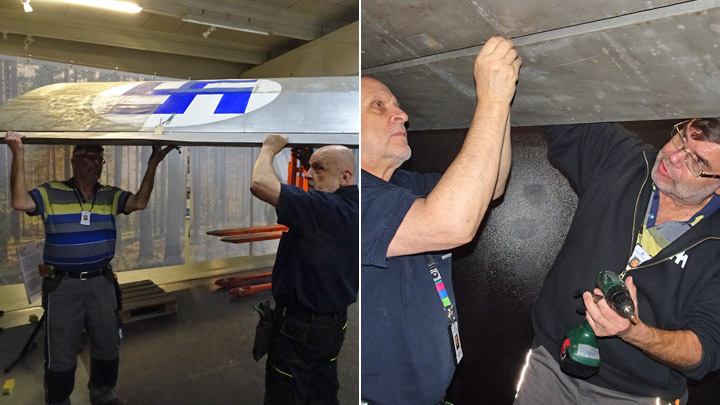
Operation "Kurki returns to Vesivehmaa" - Part 2Sunnuntai 19.5.2019 - Member of Tuesday Club The I.V.L.K.1 Kurki, designed and built by the Air force Airplane Factory in 1927, returned to the Päijänne-Tavastia Aviation museum in Vesivehmaa after a 3-year restoration project. The Tuesday Club of the Aviation Museum Society and the Finnish Aviation museum staff were responsible for the restoration work. It took about 5,000 man-hours to restore the badly damaged Kurki.
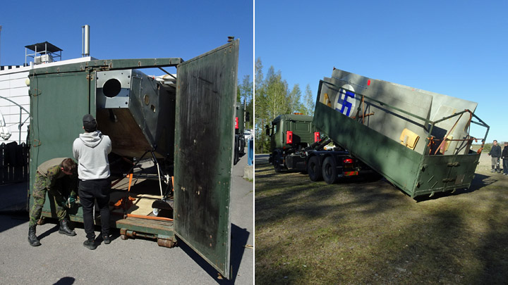
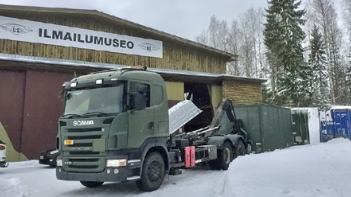
Returning Kurki to Vesivehmaa from the Finnish Aviation Museum was a 3-day project. First the plane was dismantled at the Museum for transport. Then it was transported by the Defence Forces’ truck to Vesivehmaa. And finally, the Kurki was re-assembled and placed on display in the museum hall in Vesivehmaa. The dismantling has been described in the previous blog.
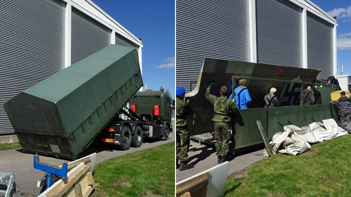
On Tuesday, May 14th before noon the Defence Forces’ truck with a trailer arrived from Tikkakoski to transport Kurki from Vantaa to Vesivehmaa. The transport assignment was also a training session for two draftees, so everybody benefitted. Kurki’s wings were loaded on the truck bed, and the fuselage on the trailer bed. It turned out that the sides of the beds were not tall enough for the wings and fuselage. Luckily the truck bed and the trailer bed both had canvas roofs on a metal frame that could be removed. It happened to be a nice and sunny day, because in rainy weather the Kurki couldn’t have been transported on an open truck bed.
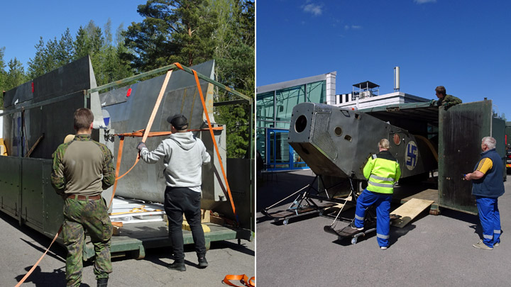
The canvas roof had to be removed before loading the wings. The fuselage, however, could be placed on the trailer bed. Only the back end of the canvas roof was opened so that the Kurki’s nose could be maneuvered on the trailer bed. The vertical stabilizer had to be dismantled to make the fuselage shorter and to fit it on the trailer. In addition to the wings and fuselage the wing struts, horizontal stabilizer, elevators and vertical stabilizer were loaded on the truck. When the cargo had been secured with cargo straps, the trip towards Vesivehmaa could begin.
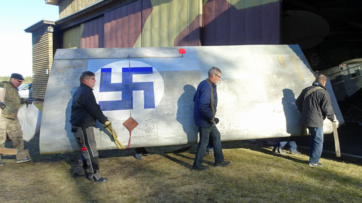
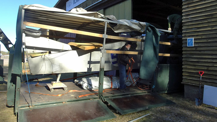
A couple of cars, carrying Tuesday Club members, drove ahead of the truck to Vesivehmaa to be there to meet the transport vehicle and to move Kurki’s wings and fuselage into the hall of Päijänne-Tavastia Aviation Museum. One of the cars towed the Tuesday Club’s trailer carrying one of the stackers that will be needed in the re-assembling or Kurki’s wings.
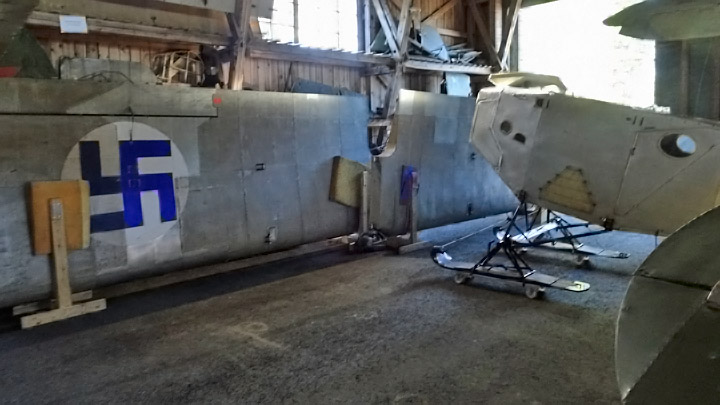
When the truck arrived in Vesivehmaa, the wings were moved first into the hall and the fuselage followed. The assembly would take place on the following day. The Tuesday Club team returned to Vantaa and the Defence Forces’ truck continued towards Tikkakoski. The team thanked the Defence Forces, once again, for helping in the transportation.
Early on Wednesday morning, May 15th the team gathered again at the Finnish Aviation Museum. All the equipment needed in the re-assembling of the Kurki was packed on a trailer, including another stacker. The six metal shelves, also assembled by the Tuesday Club, were taken on board. The Kurki assembly team consisted of about ten Tuesday Club members and of the Aviation Museum staff members.
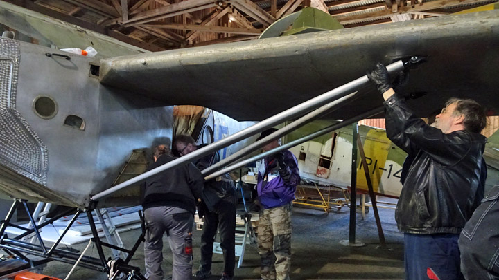
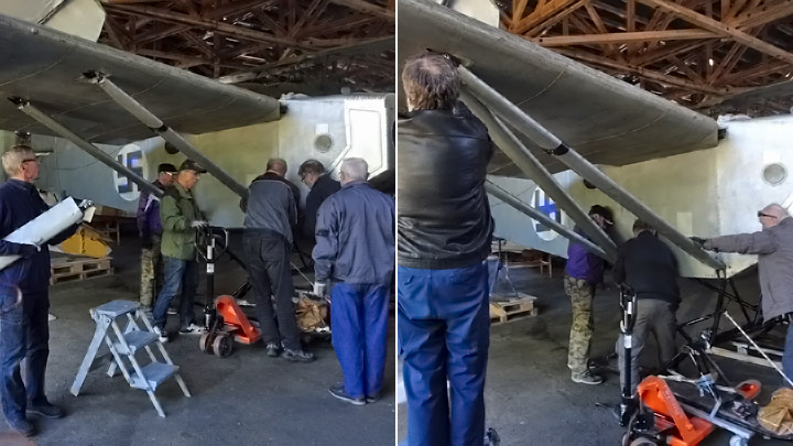
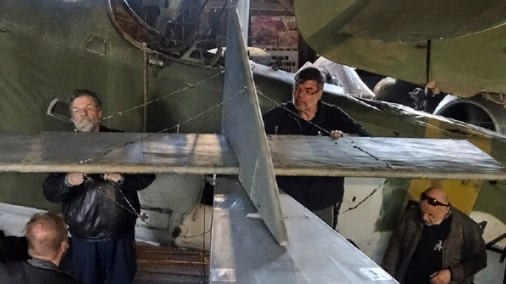
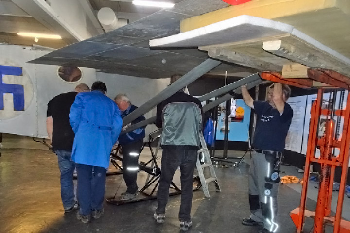
The assembly team arrived in Vesivehmaa at about ten AM and hurried to work. First the port wing was lifted into assembly height, using a stacker, and locked into place on the fuselage by the upper fasteners. Special attention was paid to the vertical position of the wing tip. The Kurki will be placed on display in the hall so that the tip of its port wing will be only a few centimeters under the lower starboard wing of the Aero Jupiter, which is placed on a stand. The sufficient distance between Kurki’s and Aero’s wings was ensured by supporting Kurki to stand slightly leaning on its port wing, with a block of wood under its starboard ski.
Then the wing struts of the port wing could be fastened, first the front strut, then the rear strut and finally the diagonal strut between them. Now the port wing had been assembled and it was supported by the struts, but the stacker couldn’t be moved yet. With the starboard wing still missing, the Kurki would have keeled over on its left side.
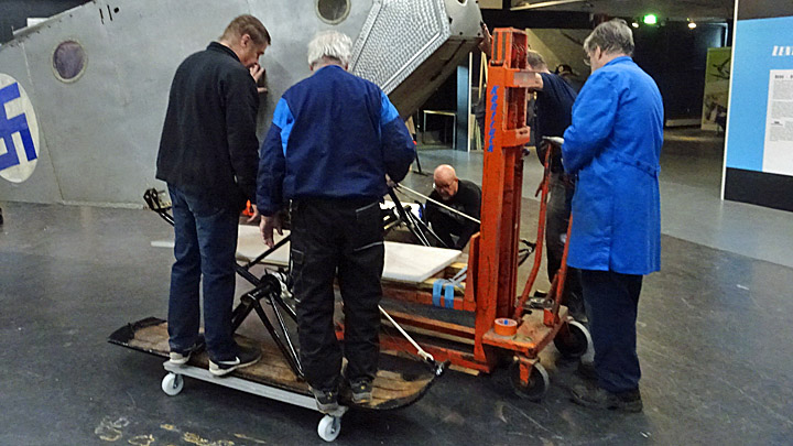
The other stacker was used to lift the starboard wing to assembly height. The wing was locked in place by the upper fastener and then the struts were fastened. Now the Kurki had its both wings in place and the stackers could be removed. Before assembling the tail part, the plane was maneuvered into its final display position. When the plane was in its place, the boards with wheels under the skis and tailskid could be removed.
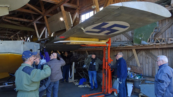
The tail was assembled by fastening first the vertical stabilizer. Then the horizontal stabilizer was fastened and onto that the elevators. The horizontal stabilizer was secured into place with a cable between the fuselage and the stabilizer. When the Kurki was dismantled at the Finnish Aviation Museum, all the control cables in the tail part were carefully labelled so that the assembly would be easy. However, some cable-shuffling was needed before all the cables had found their right places and the rudder and the elevators worked as they should.
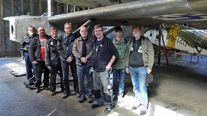
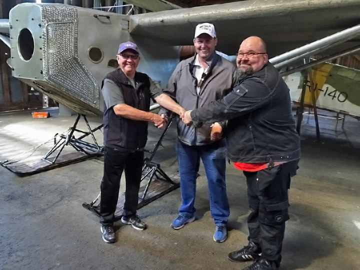
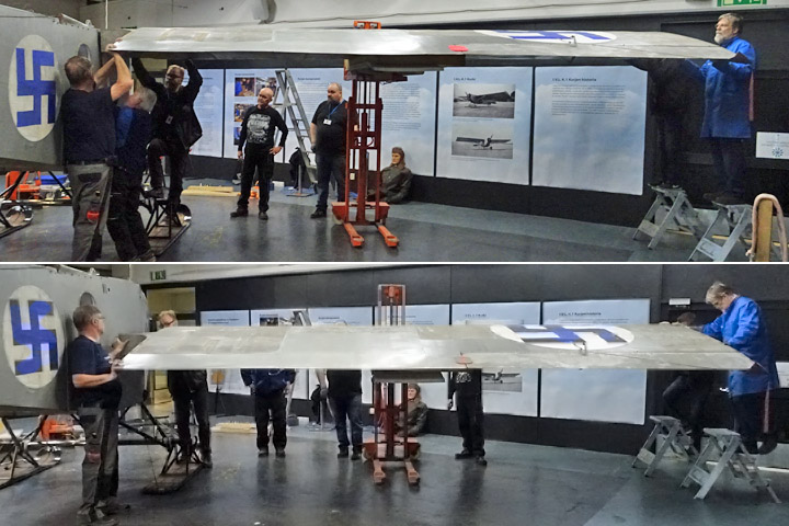
After about five hours’ work the Tuesday Club team had re-assembled the I.V.L.K.1 Kurki and placed it on display in the Vesivehmaa hall. It was time to document the moment and take a picture of the pleased Tuesday Club members.
Kuva: Janne Salonen.
Also Hannu Iivarinen (chairman of Lahti Ilmasilta), Janne Salonen (chairman of the Finnish Aviation Museum Society) and Antti Laukkanen (museum mechanic of the Finnish Aviation Museum) were pleased: the I.V.L.K.1 Kurki restoration project had been completed and the plane had returned to Vesivehmaa. Photos: Lassi Karivalo except otherwise separately mentioned. Translation from Finnish to English: Erja Reinikainen. |
|
Avainsanat: aviation history, restoring, old aircraft, I.V.L. K.1 Kurki |
Operation "Kurki returns to Vesivehmaa" - Part 1Maanantai 13.5.2019 - Member of Tuesday Club Half a dozen Tuesday Club members and members of the Finnish Aviation Museum staff gathered in the mid-hall of the Finnish Aviation Museum on Monday, May 13. The task at hand was to dismantle the I.V.L.K.1 Kurki, which had been on display for about six monthts, and prepare it for the transportation to the Päijänne-Tavastis Aviation Museum in Vesivehmaa. The Kurki is returning to the place where it was before its restoration in 2016.
The dismantling of Kurki is Part 1 in the operation “Kurki returns to Vesivehmaa”. The following episodes in the operation are the transport of Kurki from Helsinki-Vantaa to Vesivehmaa on May 14th and the re-assembling of the plane on May 15th.
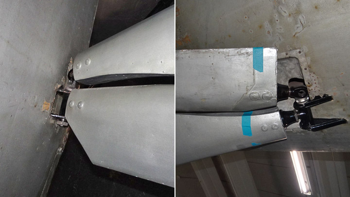
The dismantling was started by removing the venturi-tube on the wing strut of the starboard wing and unfastening the tail part. The bracing cables for the horizontal stabilizer and the control cables for the tail were unfastened and tied on a roll for the journey.
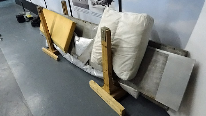
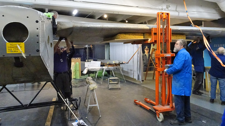
Two stackers were needed when the wings were unfastened. A padded platform had been built on the forks of the stackers. First one stacker was placed under one wing to support the wing when the wing on the other side was removed. This was necessary to prevent the plane from keeling over to one side when the wing is unfastened.
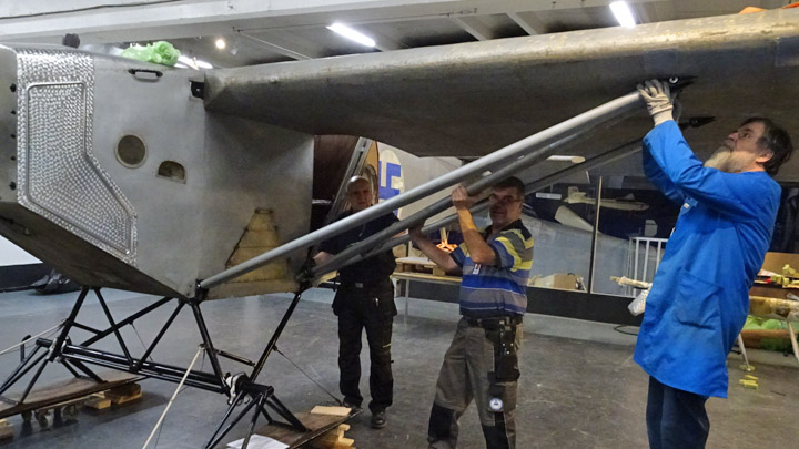
The unfastening of the wing was started by pulling out the fastening pins on the main wing brackets at the wing root and unfastening the aileron cables. Then the front, middle and rear wing struts could be removed one by one and finally the wing rested on the stacker.
The wing struts had been in the way and the stacker couldn’t be placed under the wing’s center of mass. When the struts were unfastened, the stacker could be moved towards the center of the wing. This was done by manually lifting the wing tip. The wing was resting on the stacker and it was unfastened by inching the wing manually outwards and supporting it at the wing tip. When the wing had come loose, it was lowered on the floor. It was turned up, standing on its leading edge and placed on wooden frame. The other wing was unfastened in similar manner. It would be interesting to know what the mechanics of the Air Force airplane factory had thought when watching the activities of the Tuesday Club team. In 1927 the mechanics were the professionals in assembling and dismantling the Kurki.
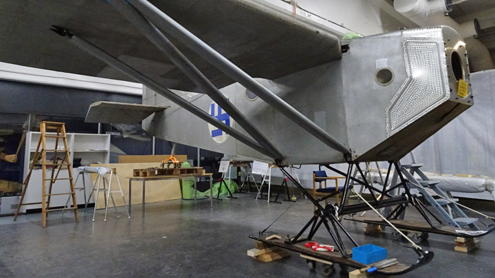
The Kurki’s fuselage was now without wings and it was lifted by the landing gear with a stacker so that boards with wheels could be placed under the skis. Another board with wheels was placed under the tailskid. Now the fuselage could be maneuvered easily when loading it for transportation.
The smaller parts, included wing struts, elevators and horizontal stabilizer, were wrapped in bubble wrap for the transportation.
Finally, all the tools for the re-assembling of the Kurki at Vesivehmaa and all other items (small ladder, paddings, timber, padded platforms for stackers, etc.) where gathered and packed to take along to Vesivehmaa. Equipment of the Defence Forces will be used for the transport.
One stacker was loaded on a trailer, to be used for re-assembling Kurki at Vesivehmaa. It will be taken there when the Kurki is unloaded from the truck. The other stacker will be taken to Vesivehmaa on May 15th when the Tuesday Club team travels there to re-assemble the plane.
The story continues in Part 2 of the project “Kurki returns to Vesivehmaa”. Photos: Lassi Karivalo except if separately otherwise mentioned. Translation from Finnish to English: Erja Reinikainen. |
|
Avainsanat: aviation history, restoring, old aircraft, I.V.L. K.1 Kurki |
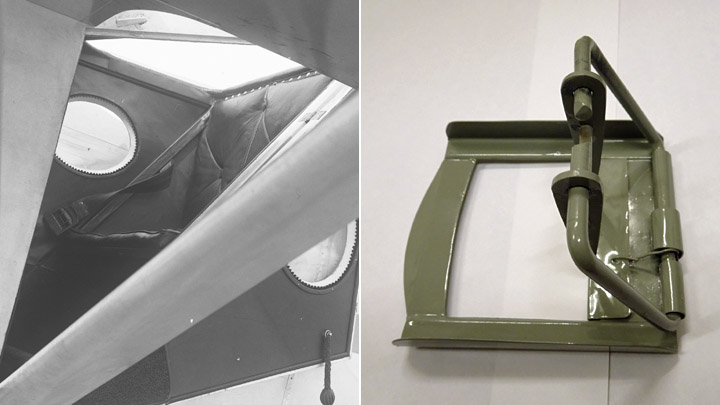
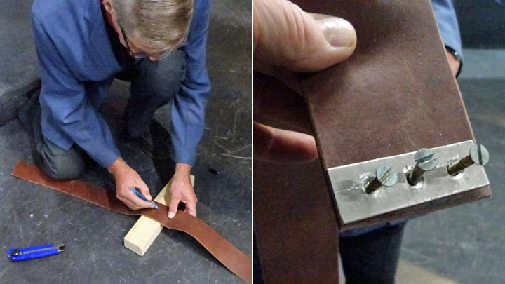
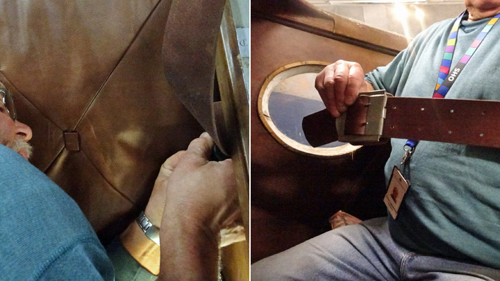
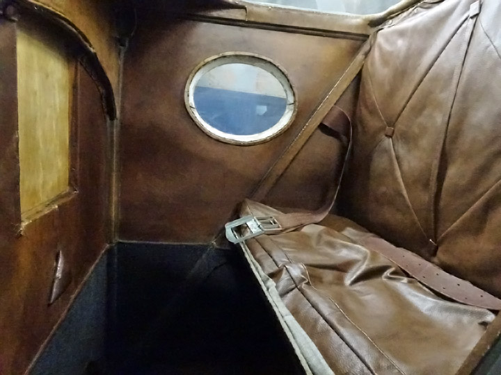
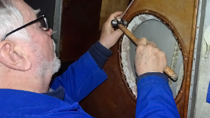
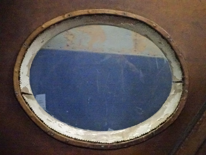
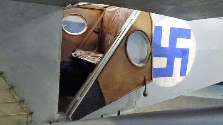
Last items of Kurki restoration workSunnuntai 12.5.2019 - Member of Tuesday Club The restoration project of the I.V.L.K.1 Kurki plane has been completed at the Tuesday Club. The Kurki was designed and built by the Air Force Airplane Factory in the 1920’s and its restoration work began in spring 2016. Kurki has been on display in the mid-hall of the Finnish Aviation Museum since December but some small items have been missing: the new seat belt in the passengers’ seat and the ribbons around the window edges. |
|
Avainsanat: aviation history, restoring, old aircraft, I.V.L. K.1 Kurki |
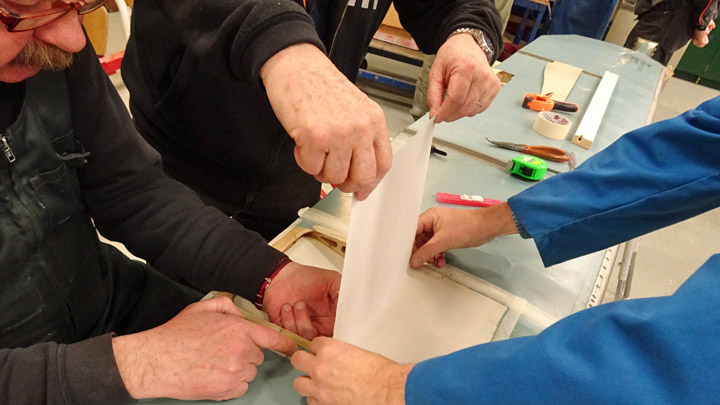
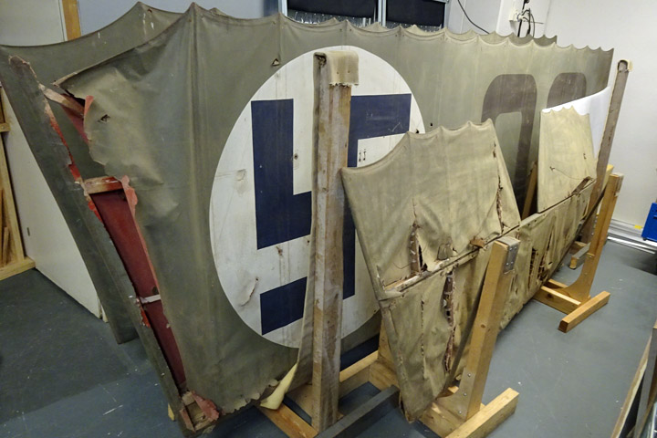
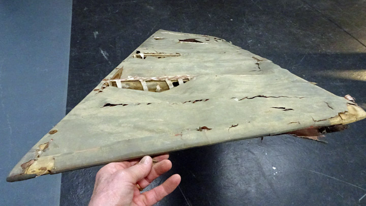
Preliminary preparations for repair of the Caudron C.59?s horizontal stabilizer and elevatorsTorstai 9.5.2019 - Member of Tuesday Club The Caudron c.59 (CA-50) airplane’s lower wings, horizontal stabilizer and elevators have been waiting at the Finnish Aviation Museum for the repair work to begin. The restoration of VL Myrsky, continuing for a few more years, and the ongoing repair of helicopter SM-1/Mi-1 rotor blades are still occupying the restoration space, so there is not yet space for the Caudron. However, the preparations for the repair of Caudron’s stabilizer and elevators have been started in another space of the museum.
Before starting the actual repair of Caudron’s wings and tail, a condition assessment was made. Based on the results of the assessment, the principles for the repair work will be decided. The plane will be restored, based on the principles of repairing conservation. This means that the damages will be repaired but everything worth saving will be saved in its original but cleaned appearance.
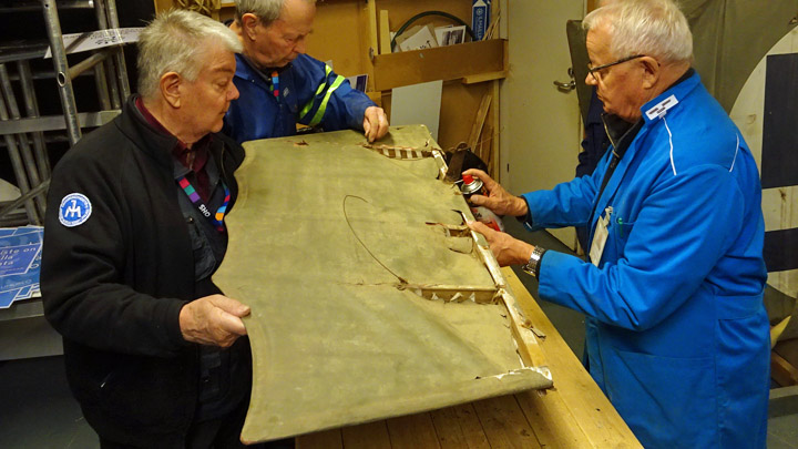
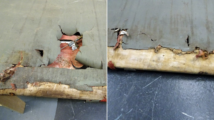
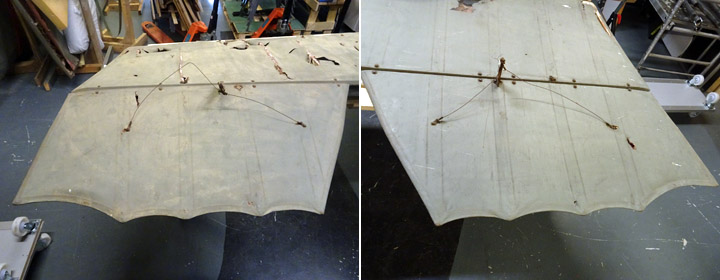
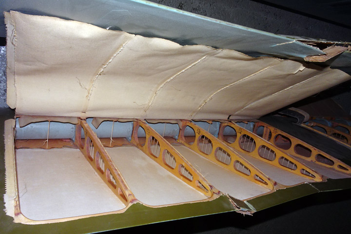
The condition assessment of the horizontal stabilizer and elevators, still in one piece, took place in late April. The fabric covering of the horizontal stabilizer is in very poor condition. There are several holes and damaged areas in the covering and the fabric has frayed very thin and it breaks like thin paper when it is touched. The fabric covering has almost disappeared on the wooden leading edge of the horizontal stablilizer. It is almost certain that none of the original fabric covering on the horizontal stabilizer can be saved. The covering will have to be dismantled and replaced. The Tuesday Club team decided to find out how the original covering of the stabilizer has been installed. The original covering principle can be seen clearly through the holes in the rotten fabric. A strip of fabric has been fastened along the ribs of the stabilizer, fastened with another strip of fabric around the ribs. The covering fabric has been sewn onto these strips. Then the covering fabric has been tightened using shrinking dope and painted.
The wooden structure of the horizontal stabilizer has bent crooked during the years, although there are steel wire stiffeners inside. The wooden frame will have to be straightened before the covering work. The wooden frame seems to be undamaged, but the real condition will be discovered when the fabric covering has been dismantled. It is possible that rotten wood will be found under the covering.
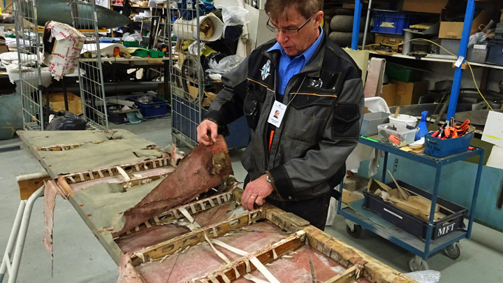
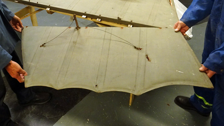
The fabric covering on the elevators is in better condition, but fragile. Some of the original covering may be saved, but whether that is possible or not, will be seen later. The covering on the elevators has been fastenede in a similar way as on the horizontal stabilizer and the wooden frame seems intact. There is no wooden batten on the trailing edge of the elevators (and not on the wings, either). The trailing edge looks like a bat’s wing, as in the fabric-covered airplanes built in the 1920’s. Unfastening the horizontal stabilizer and elevators
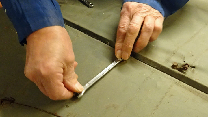
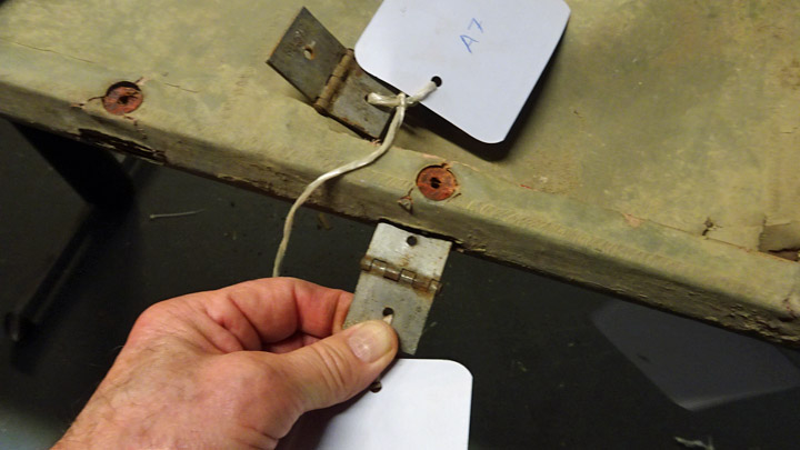
The horizontal stabilizer and the elevators are fastened to each other using ten metal hinges. The hinge roots have been embedded in the notches in the stablizer’s trailing edge and the elevators’ leading edge. The hinges have been locked in place using bolts penetrating the stablizer’s trailing edge and the elevators’ leading edge.
The hinge bolts were removed on both sides of the horizontal stabilizer. The nuts on the bolts opened easily although they were rusted, which was quite a surprise as the nuts and bolts have been in place for more than 90 years! When all hinge bolts had been removed, the elevators were pulled away from their hinges. Both elevators could be unfastened easily.
The team decided to unfasten the hinges, still fastened on the trailing edge of the stabilizer, so that they could be cleaned. This would also make the next work phases easier. The bolt of each hinge was unfastened, and the hinges could be pulled out, one by one, from their notches. The hinges were numbered so that it will be easier to install them back into their original places. The last phase was to unfasten the brackets for the upper and lower supporting wires, which are located on the stabilizer’s trailing edge on the third rib.
Caudron C.59’s (CA-50) horizontal stabilizer and elevators are now ready for the actual restoration work to begin. Photos: Lassi Karivalo Translation from Finnish to English: Erja Reinikainen. |
|
Avainsanat: aviation history, restoring, old aircraft, Caudron C.59, CA-50 |
Tuesday Club does all kinds of things!Sunnuntai 28.4.2019 - Member of Tuesday Club The Tuesday Club has an important role in the activities of the Finnish Aviation Museum and the Aviation Museum Society. These blogs usually describe the restoration and repair of museum airplanes, but the Tuesday Club does all kinds of other things as well. In the past months the Tuesday Club has been working to improve the Hawk Experience Center and there have also been different activities for the Päijänne-Tavastia Aviation Museum and for the Finnish Aviation Museum.
The Aviation Museum Society’s Hawk Experience Center gained great success last year and now it is being prepared for its 2019 summer tour in different events. The service facilities of the Experience Center have been improved during the winter.
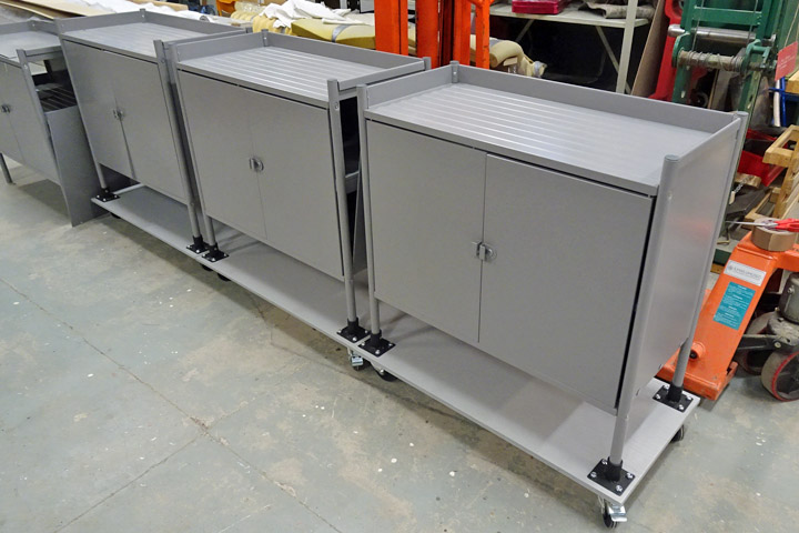
The Tuesday Club team has assembled and modified six new metal cabinets for the Hawk Experience Center. The cabinets are on wheels and easy to move around and transport. The wheels could not be directly installed on the standard tube legs of the metal cabinets. Therefore, the cabinets were fastened by their legs on a sturdy plywood board and the wheels turning 360 degrees were fastened under the four corners of the plywood board. Two of the four wheels on each cabinet have brakes. The new cabinets can be easily moved around in the Experience Center.
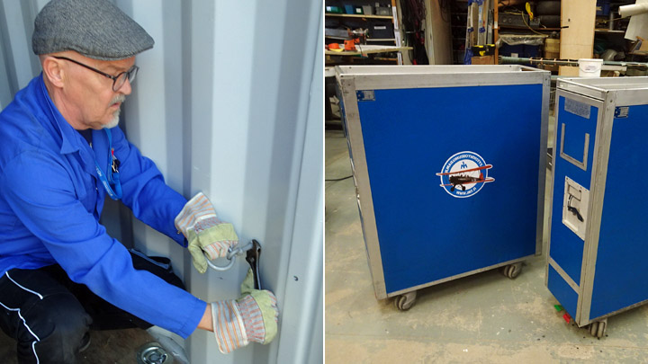
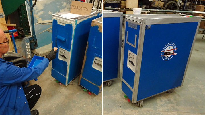
Old and rejected airplane cabin service and sales trolleys were donated to the Aviation Museum Society several years ago. The trolleys have been in the storage, waiting for a new life. Now the morning of their new life is here: the Tuesday Club team did a proper maintenance on the trolleys, painted them blue and added Aviation Museum Society logo stickers on the sides. Now the trolleys are as good as new and will be used in the Hawk Experience Center.
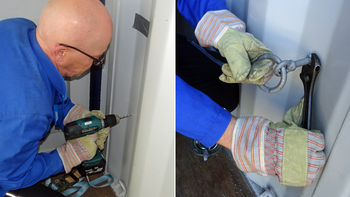
When the Hawk Experience Center is transported to the various events, the items inside it must be properly secured with cargo straps. More fastening points were needed for the cargo straps and the Tuesday Club team added four new hooking loops on the walls the Experience Center.
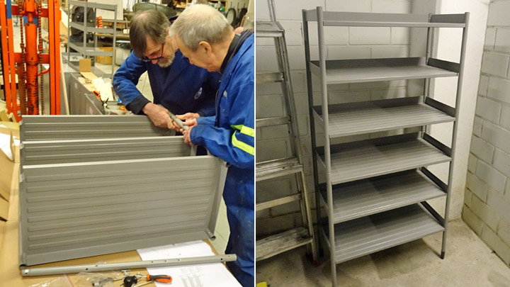
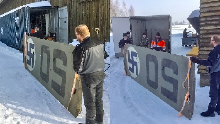
The Päijänne-Tavastia Aviation Museum has three large sea containers next to the museum hall at the Vesivehmaa airfield. The containers are used for storing museum items which are not on display. The museum staff wanted to improve the functionality and storage efficiency of the containers by adding shelves for the airplane equipment which have been stored on pallets. The Tuesday Club team assembled six new metal shelves for the sea containers at Vesivehmaa.
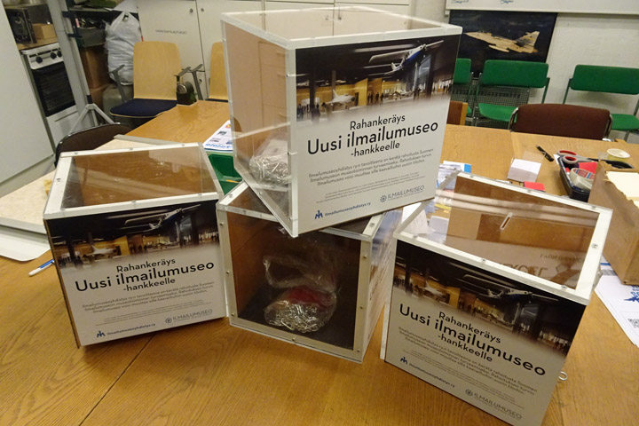
The Aviation Museum Society is arranging a three-year fund-raising campaign for the Aviation Museum’s “New Aviation Museum”-project. Several money collection boxes are needed for the aviation museums and aviation events so that as many visitors as possible can participate and donate in the fund-raising campaign. The Tuesday Club team has built six money collection boxes during the past months. The boxes are partly transparent, each box has two plexi glass walls. The first four boxes are ready to be used for collecting donations from the visitors. Similar money collection boxes were made by the Tuesday Club for the VL Myrsky II (MY-14) restoration project.
There is a staircase from the Hall II of the Finnish Aviation Museum into the restoration space of the museum. The restoration space is not open to the public and there has been a rope across the top of the stairs to indicate that the stairs are closed. The museum decided to replace the rope with a proper gate. The Tuesday Club team built a sturdy gate from 45x95mm planed battens and painted it blue. The gate was attached to the stairway railing post with hinges and a spring was added to pull the gate closed. Photos: Lassi Karivalo Translated from Finnish to English by Erja Reinikainen. |
|
Avainsanat: aviation history, restoring, old aircraft, Hawk Experience Center, Päijänne-Tavastia Aviation Museum, Finnish Aviation Museum |
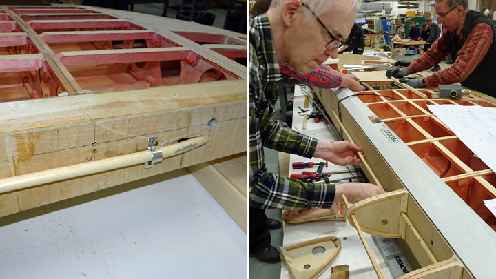
Assembly of Myrsky's wing ribs on trailing edgeTorstai 11.4.2019 - Member of Tuesday Club The preparation of ribs for Myrsky’s wings was started in the very beginning of the Myrsky restoration project in 2016. At the time ribs were made for the mid-wing section (between the wing spars) and for the leading and trailing edges.
Now the Myrsky wing restoration and assembly has reached the point where only the ribs on the wings’ trailing edge are missing.
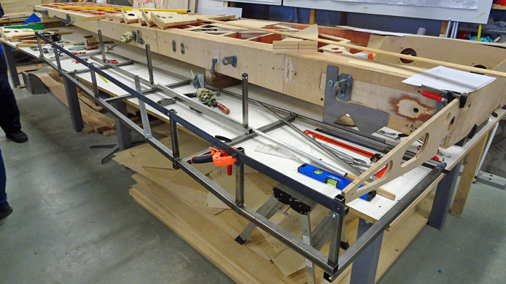
Both wings have 12 ribs on the trailing edge between the root of the wing and the aileron gap. Each rib has a notch for the flap on the lower side of the trailing edge. There are also holes in the ribs for the operating mechanisms of the ailerons and landing gear. For the installation of the trailing edge ribs the wing was placed upside down. This way it is easier to install the operation mechanisms for the ailerons and landing gear through the holes in the ribs. Furthermore, it is easier to make sure that the flap fits into the notch in the ribs.
As preliminary work the bearing block, operation bars and angle gear box for the flaps and ailerons have been installed. Also the operation mechanism for the landing gear, which penetrates the ribs, had been tested in its place.
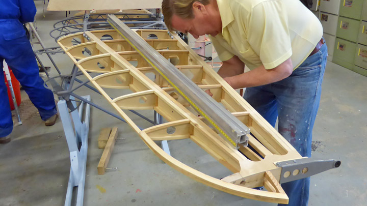
The most important preparatory work item was to build the assembly jig from steel tubes. It is necessary to use the jig to be able to place the ribs on the trailing edge in the right position. They must be exactly on the same level with each other and with the rear spar and the batten on the trailing edge.
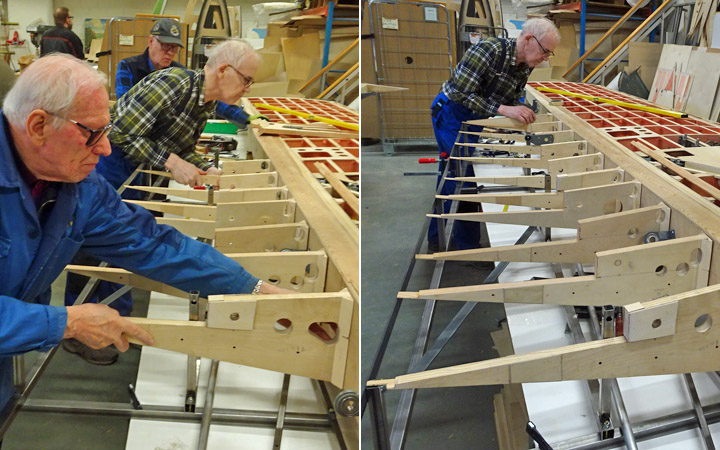
The assembly work was started on the right / starboard wing. When the assembly jig was in place, the ribs could be placed one by one between the rear spar and the rear tube of the jig. At this phase the ribs were only preliminarily fastened.
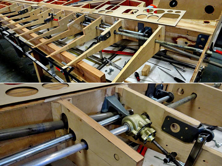
When all the ribs on the trailing edge had been placed in a neat row between the rear spar and the rear tube of the jig, the operation mechanisms of the flap, aileron and landing gear were pushed through the holes in the ribs. At first glimpse the several operation bars and mechanisms are a jumble, but each bar and tube has a purpose and has its own route through the ribs.
It was also tested how the flap settles into the notch in the ribs. The original aluminum flap pressed nicely into the notch and it also opened as expected.
The ribs will be glued onto the rear spar when the trailing edge batten which joins the tips of the ribs is ready and has been assembled into the jig. Translated from Finnish to English by Erja Reinikainen. |
|
Avainsanat: aviation history, restoring, old aircraft, VL Myrsky II, MY-14 |
Myrsky horizontal stabilizer is covered with plywoodMaanantai 8.4.2019 - Member of Tuesday Club The rebuilding of the Myrsky (MY-14) horizontal stabilizer is a good example how the restoring work progresses in phases. The phasing of restoring work is due to the prioritization of the various restoration projects. The rebuilding of Myrsky’s horizontal stabilizer has been going on whenever there has been a break in other Myrsky work, e.g. building the wings.
The frames of the horizontal stabilizer halves were finished already at the end of 2016 and then a 12-month break in the work followed. In 2018 the work was continued, and the halves of the horizontal stabilizer were covered with 1,5 mm plywood between the front and rear spars. Before the plywood covering was installed, the inner structures of the horizontal stabilizer halves and the inside surfaces of the plywood were varnished with polyurethane varnish, tinted red.
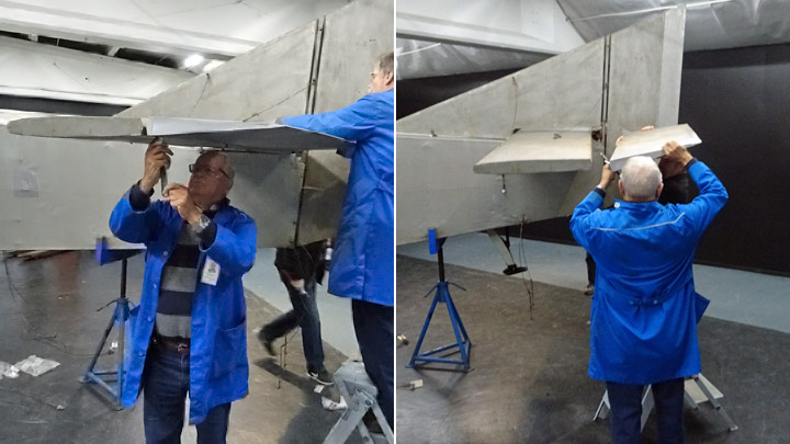
In the beginning of this year the covering of the leading and trailing edges of the horizontal stabilizer was started. The work was started at the trailing edge, where the hinge brackets for the elevator had been fastened. The trailing edge of the horizontal stabilizer is concave in shape to match the elevator’s leading edge which is hemispheric.
The covering of the trailing edge was started by carving the rectangular wooden battens on the upper and lower edge pointed, so that the trailing edge is curved inwards. As the work progressed, the shape of the trailing edge was checked regularly using a gauge to make sure that the concave shape is correct.
When the battens on the upper and lower edges had been carved, the halves of the horizontal stabilizer were fastened on an assembly jig, trailing edge upwards.
The covering work was started by cutting a thin strip of 1,5 mm plywood, matching the length of the trailing edge. Before the strip could be fastened, several supporting pieces of plywood (shaped to match the shape of the trailing edge) were glued on the trailing edge, using Casco Outdoor wood glue.
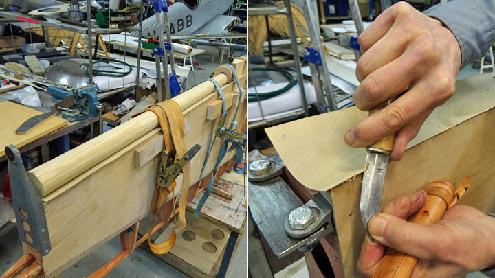
Then the plywood strip could be glued on the trailing edge. Epoxy glue was spread on the upper and lower surface of the trailing edge, on the end pieces and on the supporting plywood pieces. The plywood strip was forced against the concave trailing edge using a thick round wooden pole. The pole was fastened on the horizontal stabilizer using cargo straps. When the glue had dried the straps were removed and the additional skirts of the plywood were cut off. Both halves of the horizontal stabilizer were covered in a similar way. The halves were turned around in the assembly jig and the work on the leading edges could be started.
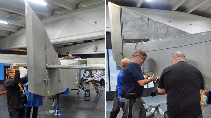
Pieces of 1,5 mm plywood were cut for the leading edge on both stabilizer halves. On the leading edge the covering piece of plywood stretches around the edge from front spar to front spar. The piece of plywood had to be shaped like a trough to match the profile of the leading edge.
First the plywood was moistened with water. Then the damp plywood was pressed tightly around the leading edge of the horizontal stabilizer and fastened using supporting battens and cargo straps. In a couple of days the plywood had dried and the straps could be removed. The Tuesday Club team was pleased to see that the plywood now had the correct trough shape and matched the shape the leading edge. An alternative work method would have been to use hot steam to moisten the plywood and then fasten it on a mold.
Before gluing the plywood, it was test assembled around the leading edge. The team wanted to make sure that the plywood trough pressed tightly on the tip batten and on the leading edge ribs and reached on both sides as far as the front spar. The plywood covering of the mid-section of the horizontal stabilizer had been glued in an earlier work phase on the front spar. The leading edge covering meets this mid-section plywood with a scarf joint.
When the leading edge plywood covering was in place, the epoxy glue was mixed and cellulose fibre was added as binder. The glue was spread with a brush on the leading edge batten, ribs and the edge of the mid-section plywood on the front spar. The trough shaped plywood covering was pressed against the leading edge and fastened tightly using supporting battens and cargo straps.
The scarf joint of the two pieces of plywood connecting on the front spar was secured with staples from a stapling gun.
After a couple of days the cargo straps were removed. The team members knocked on the leading edge plywood to make sure that it had been properly fastened on the leading edge batten and the ribs. The staples securing the scarf joint on the front spar could be removed.
When the seams of the scarf joint had been ground smooth, the work was ready. Both halves of the horizontal stabilizer were covered in a similar way. Photos: Lassi Karivalo Translation from Finnish to English: Erja Reinikainen. |
|
Avainsanat: aviation history, restoring, old aircraft, VL Myrsky II, MY-14 |
Caudron C.59 parts were transported from Vesivehmaa to VantaaSunnuntai 17.3.2019 - Member of Tuesday Club The Caudron C.59 (CA-50) will be the next restoration project for the Tuesday Club. The two lower wings, horizontal stabilizer, elevator and wing struts were transported from Päijänne-Tavastia Aviation Museum at Vesivehmaa to the Finnish Aviation Museum in Vantaa. The Caudron has been stored in parts at Vesivehmaa and it is included in the airplane catalogue of the War Museum.
Photo: Hannu Iivarinen The Caudron has been used by the Finnish Air Force in 1923-1929 as a training plane. The parts of the Caudron were transported by the Finnish Defence Forces and the actual transport task was a part of the draftees’ training. The two fabric-covered wings have been stored in the sea container next to the museum hall. The horizontal stabilizer, elevator and the wing struts have been in the museum hall. The main fuselage of the plane remained in the museum hall and it will be transported later to be restored.
Photos: Hannu Iivarinen A team of Finnish Aviation Museum staff and Tuesday Club members left Vantaa very early in the morning. Their task was to pack and load the Caudron’s parts into the Defence Forces’ truck. The team had a collection of wing supports, cushions and cargo straps which would be needed in the packing.
Photo: Matias Laitinen The weather was cold and snowy, so the team was a little bit doubtful whether the doors and locks could be opened because of the arctic conditions. However, at Vesivehmaa snow had been cleared and the doors of the hall and the container were accessible. However, some effort was needed before the lock of the container was open.
Photos: Matias Laitinen When the Defence Forces’ truck arrived from Tikkakoski, the loading of Caudron’s parts could be started. First the two lower wings were moved from the sea container and then the elevator with horizontal stabilizers, and finally the wing struts. The parts were placed on the wing supports and cushions and secured with cargo straps on the fastening points in the cargo space. The team wanted to make sure that all the parts were secured so that no damage could happen during the transport. When everything was ready the team had a coffee break before setting on the road.
Photos: Jorma Laakso & Matias Laitinen The truck arrived at the Finnish Aviation Museum soon after noon. The cargo straps were unfastened and the Caudron parts were moved into the Museum, but not yet into the restoration space.
Photo: Matias Laitinen It will take a while before the Tuesday Club team and the Museum’s staff will start the restoration work of the wings, elevator and vertical stabilizer and the wing struts. Before that the Caudron’s parts brought from Vesivehmaa will go through a thorough condition assessment. Based on the results of the assessments the restoration methods will be chosen. Traslated from Finnish to English by Erja Reinikainen. |
|
Avainsanat: aviation history, restoring, old aircraft, Caudron C.59, CA-50 |
Fabric covering of SM-1 rotor blade is patchedTiistai 12.3.2019 - Member of Tuesday Club The repair of the SM-1 helicopter’s (HK-1) two rotor blades (No1 and No3) has been going on for about a month. The fractures on the trailing edge of the blades have been repaired. Now the focus is on repairing the damages in the fabric and plywood covering. The damaged fabric covering has had to be dismantled in large areas.
The installation of the new fabric covering was first tested in the small damaged area in the middle of blade No 3. The damaged fabric had been dismantled in an area which was two rib-sections wide and reached up to the plywood-covered area in the leading edge and to the wooden strip on the trailing edge. The new fabric will not be sewn onto the ribs as it has originally been. The fabric has been sewn on the ribs in such a complicated way that it is not possible to follow a similar procedure in the repair work. The Tuesday Club team considered the situation. If the rotor blade had been damaged during the using period of the helicopter, the wooden and fabric covered rotor blade wouldn’t have been repaired. Most likely a new rotor blade would have been installed. The Team decided that their task was to repair the rotor blades so that they would look intact and the outcome of the repair work would resemble the original blade structure as far as possible.
The patching of the damaged area was started by fastening painter’s tape around the edges of the dismantled area so that the original surface was visible about 1,5 cm at the edges. The original fabric areas were sanded smooth using sandpaper 250. The sanding dust was removed using a cloth moistened with a mixture of Sinol and water.
The area to be repaired was two rib sections wide (25 cm) and reaching from the trailing edge up to the plywood on the leading edge (35 cm). The Team decided to fasten the new cotton fabric covering by its edges using contact adhesive. Small fabric patches can be fastened by using only shrinking dope.
A piece of fabric matching the size of the hole in the rotor blade was cut from cotton fabric, which is used for covering airplanes. Scissors with zigzag blades were used so that the fabric will have a saw-toothed edge, which will fasten more firmly onto the bottom material than a straight-cut fabric edge. The rotor blades of SM-1 helicopter have originally been covered with cotton fabric and that is why the Team didn’t use modern reinforced fabric in the repair work.
The patch of new fabric was first glued onto the existing material at the top edge. The Team used contact adhesive (Bostik) and the adhesive was spread in equal width on the new fabric and on the edge of the repair area. When the adhesive had dried for about ten minutes, the upper edge of the fabric was pressed, pulling the edge at the same time, onto the upper edge of the opening.
Then the sides of the fabric patch were glued. This was done in 10 cm long phases, advancing towards to the trailing edge of the rotor blade. When the edges of the patch, with adhesive, were pressed against the edges of the dismantled area, the premature contact of the surfaces was prevented by using a piece of cardboard between the surfaces. When the work progressed, the piece of cardboard was slowly pulled away.
Working in a similar way as when fastening the upper edge of the fabric, the side edge of the fabric was pulled in both directions when fastening it. This is how the fabric got its preliminary tightness before the actual tightening with shrinking dope. When the new fabric had been glued by its edges all the way up to the wooden strip on the trailing edge, the patch was ready to be tightened.
The tightening of the covering fabric will be started by water treatment where the fabric is sprayed wet a few times and left to dry. Then the actual tightening will be done by applying several layers of nitrocellulose varnish on the fabric. The varnish, i.e. shrinking dope, will give the fabric its final impermeability and tightness. Photos: Lassi Karivalo Translation: Erja Reinikainen |
|
Avainsanat: aviation history, restoring, old aircraft, helicopter, SM-1 |
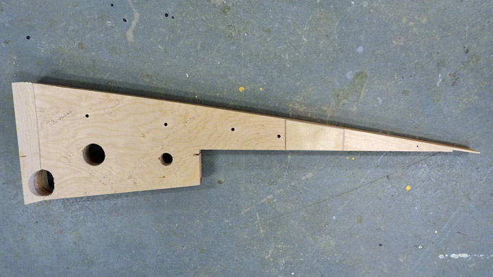
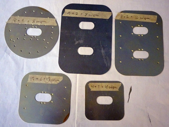
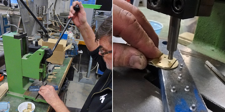
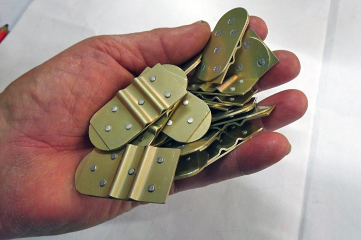
Making access panel latches for Myrsky's wingsMaanantai 4.3.2019 - Member of Tuesday Club There are dozens of access, maintenance and operation panels on the wing of Myrsky. The panels are of five different sizes.
The restoration project team has some original Myrsky wing access panels, but majority of the panels will have to be made. There is a latch in the middle of each access panel to open and close the panel. The “seesaw type” latch has a hinge in the middle and the latch is opened and closed by pushing it with a finger.
Because each access panel on the wing has one or two latches, more than 70 latches are needed on the two wings of the Myrsky and on the test wing. The restoration team decided to make all the identical latches in a serial process.
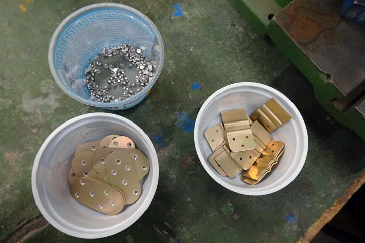
The frame of the latch is made of two aluminum plates which are riveted together. The access, maintenance and operation panels had been cut from 1 mm aluminum plate, using a laser cutter. This work method was used also to cut the latch frames. Holes for the rivets were also made. The rivets are 2,5x3,5 mm aluminum rivets with countersunk heads. Folds were made on the plate on the inside of the latch, the folds are needed for the hinge and the locking wire.
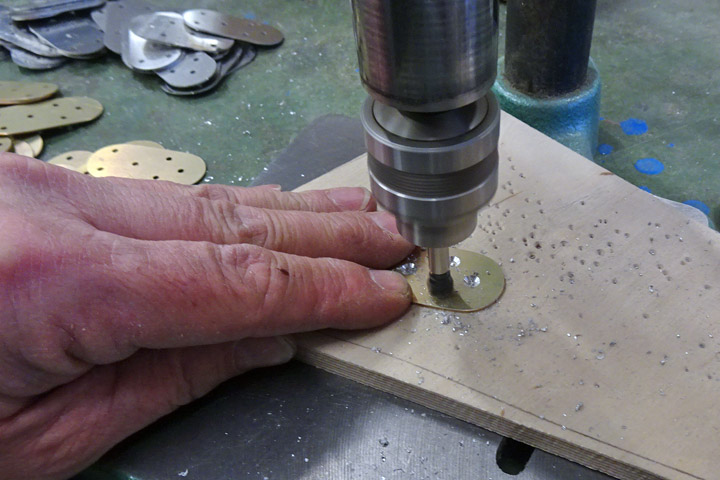
The first phase in the making of the latch frame was to make the holes for the rivets on the outer plate of the latch so that the head of the rivet will be on the level of the plate surface. The holes were made with a special drill piece on a vertical drilling machine.
The frame of the latch was made by riveting the inner and outer plates together. A powerful manual riveting tool was used. The inner and outer plates were put on the riveting table with the inner surface on top. Rivets were placed into the holes and then the rivets were pushed into place using the riveting tool.
Each latch frame has six rivets so the tool had to be used several times before the required number of latch frames were ready for further processing. Photos: Lassi Karivalo Translation: Erja Reinikainen |
|
Avainsanat: aviation history, restoring, old aircraft, VL Myrsky II, MY-14 |
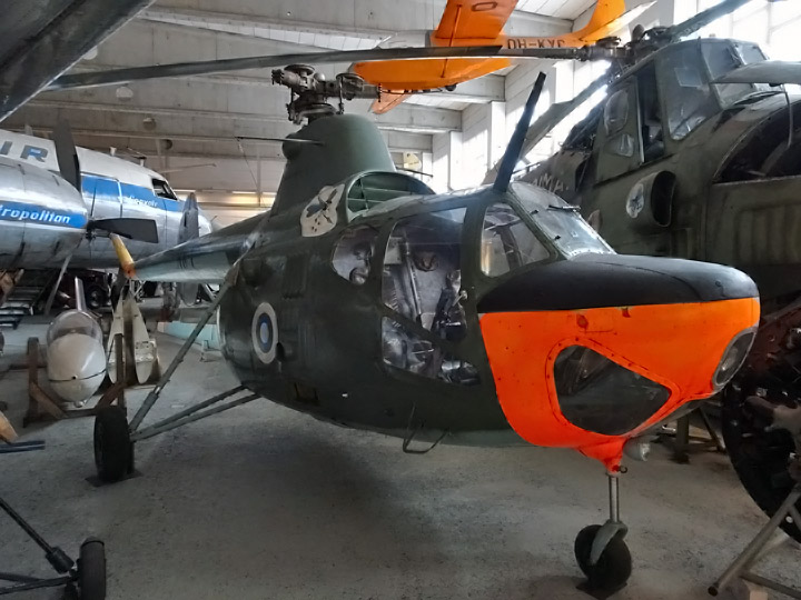
Rotor blades of helicopter SM-1 are being repairedMaanantai 25.2.2019 - Member of Tuesday Club A Polish helicopter SM-1 (SM1/600 SZ) is on display in the Finnish Aviation Museum’s Hall II. It has been in use in the Finnish Air Force and it has the registration number of HK-1. The helicopter was made in Poland, based on the principles of the Soviet Mil Mi-1 copter. The Finnish Air Force had four Polish SM-1’s in use during 1961-1967. These helicopters were assembled Finland at the Air Force hangars in Tampere in early 1961. Helicopters HK-1 and HK-2 were modified for training purposes.
The SM-1 has rotor blades which are over 6 meters long and have mainly wooden structure. Each blade has a round metal tube as a spar, surrounded by wooden ribs on the leading and trailing edges. The leading edge of the blade is covered with plywood and the tip of the edge has a narrow metal strip, covering the full length of the blade.
The tip of the blade has plywood covering, otherwise the blade has fabric covering. The upper surface has been painted dark green and the lower side pale blue. The root of blade No1 has the manufacturer’s labelling SM-1, No 1R10012, BLADE No 1, ATTEST No 844, DATE 11.1.1961.
Two of the three rotor blades of HK-1 have been damaged. It is not known when and how this happened. The Tuesday Club agreed with the Finnish Aviation Museum and the Aviation Museum Association that the rotor blades will be repaired by the Club. The rotor blade No1 was carried from the museum’s Hall II into the restoration space on February 5th, 2019 and the repair work was started.
The trailing edge of the rotor blade consists of the wooden strips on the upper and lower surface, which have been glued together at the edge and to which the ribs are fastened. The trailing edge on blade No1 is fractured in two places. The plywood and fabric covering has some holes, tears and scratches and the paint is badly flaking in some places.
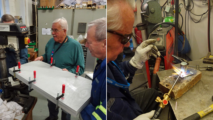
The repair work was started at one of the fractured points on the trailing edge. There the wooden strip on the lower side of the trailing edge has broken into three parts. To have a good view of the damage, the torn fabric covering around the area was dismantled. The broken pieces of the trailing edge were removed, cleaned and fitted together on a table. The team decided to glue the pieces together and replace a small missing piece with epoxy.
The pieces of the trailing edge were glued together against the wooden strip on the upper side of the blade, using clamps. The glue was Erikeeper Plus. When the glue had dried, the clamps were removed, and the team was happy with the result. There were small gaps between the glued pieces and a small piece was missing, so the gaps were filled with epoxy. When the epoxy had dried, the trailing edge was in good condition and the outcome was even better than the team had expected. Finally, the surface of the glued trailing edge was buffed out. Now one of the fractures on the trailing edge had been repaired and it was left to wait for the covering of the damaged area.
There are bruises and cracks in the plywood covering and in some places the ribs under the covering have been damaged. The small cracks in the plywood were repaired using epoxy. When the epoxy had dried, the surface was honed smooth. The team hasn’t yet decided how to repair the larger cracks in the plywood covering.
The small holes in the fabric covering can be repaired using fabric patches. However, in most damaged places the fabric will have to be dismantled as far as the nearest ribs and to the leading and trailing edges. This is necessary in order to have sufficient gluing surface around the edges of the new fabric. The team hasn’t decided whether the new fabric will be glued onto the ribs or sewn on the ribs (as it has originally been). The new fabric will be pulled tight using shrinking dope.
The fabric covering was cut off in the damaged area in the mid-section on the upper surface of the blade. A thin rim of fabric, about 1 cm wide, was left on the edges of the ribs. When the fabric was removed up to the plywood covering on the leading edge, the team noticed something strange. There was a thin layer of paper under the plywood covering on the leading edge, resembling wax paper. There was no paper under the fabric covering and the team didn’t know why it had been installed under the plywood.
The painted surface of the fabric covering on the rotor blade is badly flaking and damaged in large areas. The paint peels off in thin strips. In some places it may be possible to fix the flaking using varnish or paint but in the worst places the flaking and damaged fabric will have to be dismantled and replaced. This is how the place on the upper side at the root of the blade had been repaired. The SM-1 rotor blade repairs are well on the way. Photos: Lassi Karivalo. Translation: Erja Reinikainen. |
|
Avainsanat: aviation history, restoring, old aircraft, helicopter, SM-1 |
Leading edge of Myrsky wing is assembledKeskiviikko 20.2.2019 - Member of Tuesday Club The Tuesday Club team has been working on the restoration of VL Myrsky’s wings. The work has progressed to the phase when the ribs on the leading edge of the wing can be installed. Previously the ribs have been prepared for the assembly and the tube for the electrical cable of the navigation light has been fastened on the front spar.
The ribs for the leading edge of Myrsky’s wings were made about a year ago. Triangular wooden battens were fastened on the root of each rib so that they can be glued onto the front spar. This arrangement makes the gluing surface wider on the rib root. Before gluing the ribs into place their sides were protected against humidity using polyurethane varnish, tinted red.
The aluminum tube for the electrical cable of the navigation light on the wingtip was installed before the ribs were installed. The aluminum tube was fastened in the middle of the front spar side facing the leading edge. Aluminum clips were used for fastening the tube on the spar. A notch for the tube had to be carved on the root of each rib before the ribs could be glued onto the front spar.
It is important that all the ribs are glued onto the front spar so that their tips are fully in line. If they are not, this will cause problems when covering the leading edge with plywood. A long metal bubble level was the perfect tool for making sure that the rib tips are in line.
The level showed that the ribs had slightly different lengths, a couple of millimeters. To compensate the error, thin strips of plywood were glued on the root of the shorter ribs. Several ribs had to be modified to make them slightly longer so that the tips met the level. When all the rib tips were in the correct position, a thin connecting wooden batten (8x8 mm) was pushed through the hole at the tip of each rib. When the batten was in place, the ribs were glued onto the front spar and secured into place with clamps.
When the glue had dried, the installation of the supporting battens between the ribs could be started. The battens are installed on the ribs on the upper and lower side of the wing, covering the full length of the wing. Strips of plywood were glued on both sides of each rib, at the lower edge. Then the supporting battens were glued onto the strips.
The battens on the upper side of the ribs will be installed when the wing has been turned around. Another supporting batten was added on the front side of the batten which penetrates the tips of the ribs. Now the tip batten became thicker and the front edge of the batten is at the level of the rib tip. The ribs were installed in a similar way on the leading edge of Myrsky’s both wings. Photos: Lassi Karivalo Translation: Erja Reinikainen |
|
Avainsanat: aviation history, restoring, old aircraft, VL Myrsky II, MY-14 |
Caudron C.59 will be next project for Tuesday ClubTorstai 24.1.2019 - Member of Tuesday Club It has been agreed with the Finnish Aviation Museum that the following project for the Aviation Museum Association’s Tuesday Club will be the Caudron C.59. At the moment the airplane is in storage at the Päijänne-Tavastia Aviation Museum in Vesivehmaa. The fabric-covered Caudron C.59 (CA-50) is in poor condition, having been in storage for more than 90 years. Its restoration work is estimated to take a couple of years.
Photo: Wikipedia One of the main work items is to repair the damages on the covering of Caudron’s wings, rudder and horizontal stabilizers. One wing has only the supporting frame structure which is so bent that the wing will have to be straightened and covered with new material. The fuselage covering is also badly damaged. The cockpit, engine space and landing gear will need thorough repair and maintenance. In the near future it will be decided in which order the parts of the Caudron C.59 are brought to the Tuesday Club for restoration. The Finnish Air Force Museum has an 8-cylinder V-engine Hispano Suiza 8 Ab, which has been used in Caudrons and other planes. This would be a good addition to the plane under restoration.
The Tuesday Club is prepared to start working on the Caudron C.59 when the surfaces of the Junkers 50 A Junior have been cleaned and the plane moved into the II hall of the Finnish Aviation Museum. The rotor blades of the Aviation Museum’s helicopter SM-1 (Mi-1) will also be repaired first. It may be possible to begin the restoration of the Caudron while the rotor blades are still under repair. Some of Caudron’s parts will be transported from Vesivehmaa to the Tuesday Club before the end of February.
The Caudron C.59 was used for the advanced training of pilots and 3 planes were bought in 1923 from France for the Finnish Air Force. Two of the planes were destroyed in a crash. The Caudron C.59 which is at Vesivehmaa has the identification number CA-50. It did its last flight on October 1st 1929 and was put into storage. The Caudron C.59 resembles the Caudron C.60, used by the Finnish Air Force (it had 64 Caudron C.60’s). Due to the Hispano Suiza 8 Ab V-engine the front fuselage of the Caudron C.59 is slightly narrower than the thick nose of the Caudron C.60 with its rotating Clerget 9 star engine. Most likely the Caudron C.59 CA-50 in Finland is the only remaining individual of this plane type in the world. The Caudron C.60 (CA-84), restored by the Tuesday Club, is on display in the Finnish Aviation Museum. Photos: Lassi Karivalo except when separately otherwise mentioned Translation: Erja Reinikainen |
|
Avainsanat: aviation history, restoring, old aircraft, Caudron C.59, CA-50 |
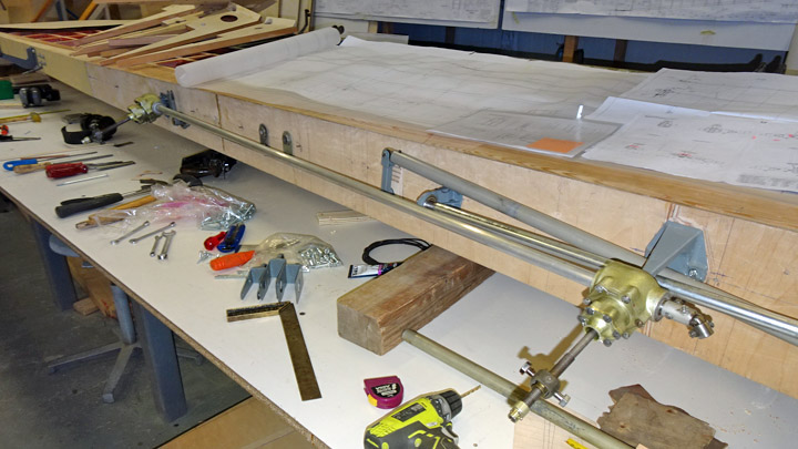
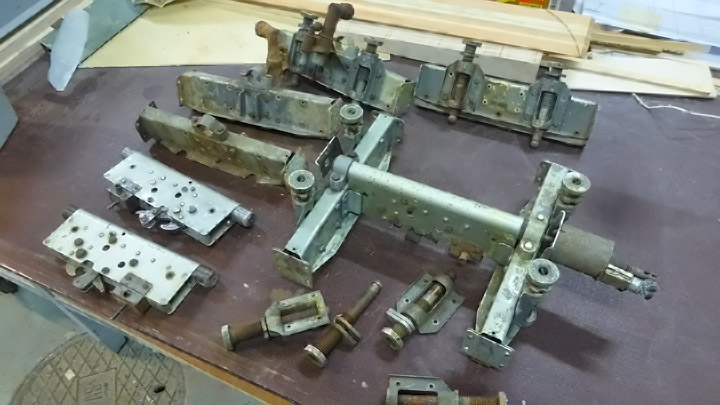
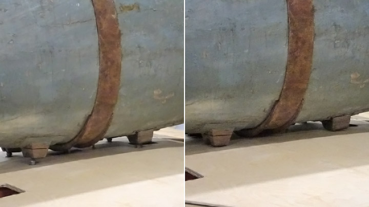
Rack for auxiliary fuel tank of Myrsky is testedMaanantai 14.1.2019 - Member of Tuesday Club The VL Myrsky fighter has inside both wings a rack for fastening an auxiliary fuel tank or a bomb. The Tuesday Club team had several original parts of the rack for the Myrsky restoration work. The rack parts were repaired and cleaned and assembled together to form the racks on both wings of the Myrsky and also for the short wing built for test purposes. The rack on the test wing has been already tested.
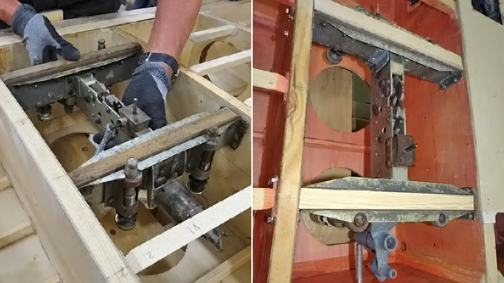
The racks had been installed on both wings on the Myrsky. The area around the rack had also been preliminarily covered with new plywood so that the rack could be tested. Holes were made into the plywood covering for the rack mounting locator pins and the catch, which the auxiliary fuel tank or the bomb is locked on. Another hole was made for the indication pin, which forwards the information to the pilot when the auxiliary fuel tank or bomb has been released.
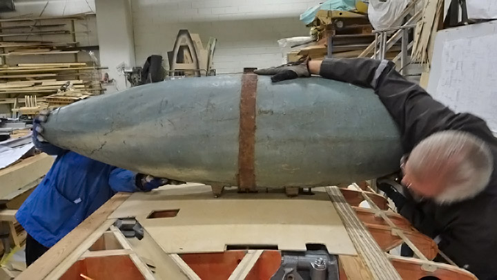
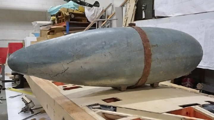
The testing of the rack could be done easily as the wings are on the assembly jig with the lower side upwards. For the test procedure the team could use an original Myrsky auxiliary fuel tank - fortunately a bomb wasn’t needed for the testing! The team decided to test the rack on the starboard (right) wing.
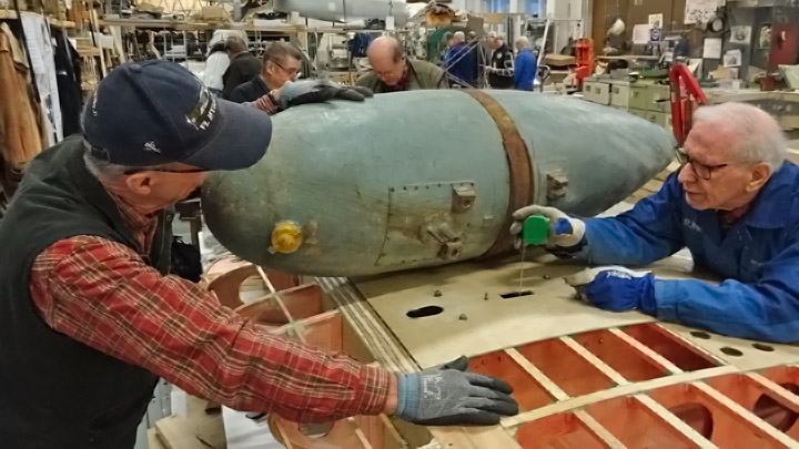
The auxiliary fuel tank was lifted upside down on the wing, which was upside down on the assembly jig. The tank was placed above the rack so that the four wooden steering blocks met the mounting locator pins, which penetrated the wing covering. The lock ring on the surface of the auxiliary fuel tank slid through the hole on the wing covering towards the lock catch on the rack.
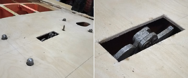
The team was annoyed to discover that the fuel tank didn’t lock on the rack. When the tank was lifted and the distance of the lock catch from the wing surface was measured, the team noticed that the rack, placed inside wing between two wing ribs, was located about 5 mm too deep. The lock ring of the auxiliary fuel tank didn’t reach the lock catch. Although the rack had been installed according to the measurements on the drawings, this was what the situation was.
The team sighed and continued working, dismantled the rack and installed it again, this time 5mm closer to the surface of the wing. The auxiliary fuel tank was tested again on its place, this time it locked perfectly on the lock catch of the rack. Photos: Lassi Karivalo Translation: Erja Reinikainen |
|
Avainsanat: aviation history, restoring, old aircraft, VL Myrsky II, MY-14 |
Kurki restoration work has been completed and plane is on display!Torstai 27.12.2018 - Member of Tuesday Club The Tuesday Club team worked hard before Christmas to finish the I.V.L. K.1 Kurki restoration work so that the plane could be placed on display at the Finnish Aviation Museum before Christmas.
The fuselage of Kurki was in the Middle hall of the Aviation Museum, where the other parts were assembled as soon as the painting work of the new plywood surfaces on the tail parts and wings had been completed. The first parts to be assembled on the fuselage were the elevator and the horizontal stabilizer. The assembly work went well, and the control cables could be installed.
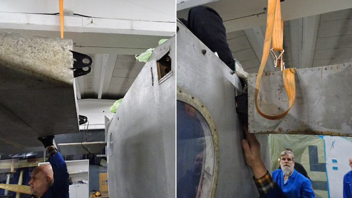
Kurki’s large wings had been partly covered with new plywood and the painting work on the new areas on the right / starboard wing were completed first. The assembly work of the starboard wing could be started in the beginning of December. The wing was lifted to the correct assembly height using a stacker. The lifting was secured with a cargo strap around the wing, attached on a beam in the ceiling. The cargo strap also prevented the Kurki from falling over when it had only the starboard wing assembled.
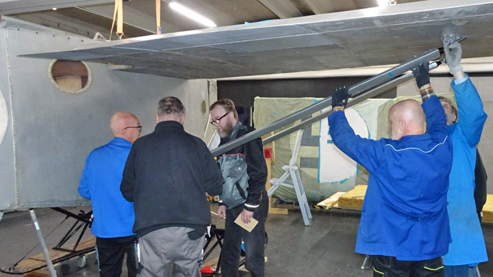
The lifting of the wing went well and the fastening elements on the root of the wing were pushed into the holes in the fuselage. The wing was easily locked in place. The assembly of the three wing struts was far more difficult. Four of the six wing struts had been made by the Tuesday Club team, because only two original parts were available. The team had no information on the actual shape of the fasteners at the ends of those struts and had improvised. This was why the strut fasteners had to be slightly modified during the assembly work to make them fit on the fasteners on the fuselage and on the wing. Finally, the fasteners slid into position and could be locked.
The painting of the port wing had been completed and the assembly work could be started on December 11th. The assembly procedure followed the procedure with the other wing, everything went smoothly until the wing struts were installed. Again, the fasteners on the wing struts had to be modified to make them fit. The wing was fastened in place and the wing struts fastened. Now both wings had been assembled and the securing cargo line could be removed. The ailerons were assembled on the wings and finally Kurki was a real airplane, for the first time in 91 years. When the test flights were finished in the autumn in 1927 the Kurki was dismantled and the parts were stored.
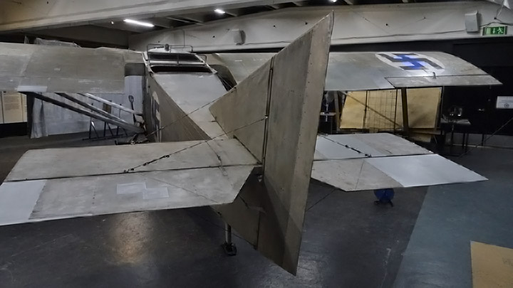
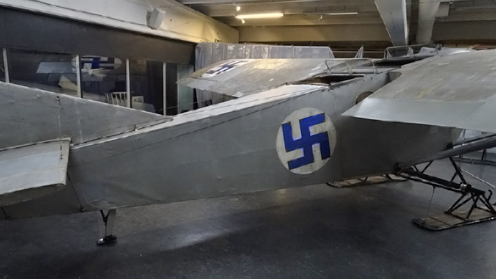
The Kurki can’t be described as smooth and beautiful! No wonder that it was nicknamed at the time as “Järvinen’s box”, according to its designer Asser Järvinen, the manager of the Airplane Factory. However, the Kurki is impressive with its huge wings. The Tuesday Club wish they had the proper Siemens-Halske 12 engine for the Kurki so that the plane would look like a real flying airplane. Unfortunately, there is not a single SH 12 engine available in Finland for the Kurki.
The remaining task was to turn Kurki around in the Middle hall of the museum, into its final display position. Maneuvering the plane was fairly easy, the Kurki rested on its skis and tail wheel on pallets with wheels. The problem was that the final assembly work had taken place under the main ceiling beam in the middle of the hall and now the wingtips of the Kurki nearly touched the walls of the hall. The plane was inched into a diagonal position in the hall, but that was a close call: there was a marginal of 5 cm between the wingtip and the wall.
When the Tuesday Club was working on the assembly, the Aviation Museum Society had been making preparations for the Kurki exhibition, including information posters. The posters describe the history of Kurki and also the restoration work at the Tuesday Club. There is also information about the design and construction of Kurki and about the history of the Air Force Airplane Factory, which operated in the Viapori sea fortress in the 1920’s.
The Kurki exhibition was opened on December 18th. The plane is on display in the Middle hall of the Finnish Aviation Museum, at least until the end of January but probably longer. The exhibition is definitely worth a visit: Kurki is one of the most extraordinary products of the Air Force Airplane Factory. |
|
Avainsanat: aviation history, restoring, old aircraft, I.V.L. K.1 Kurki |
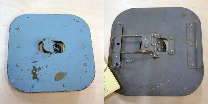
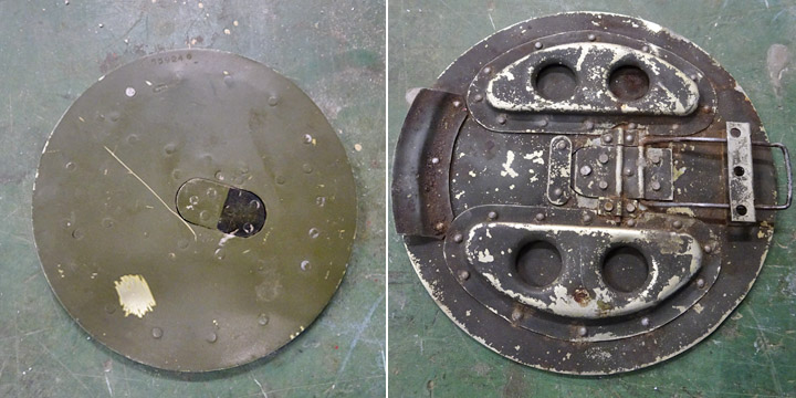
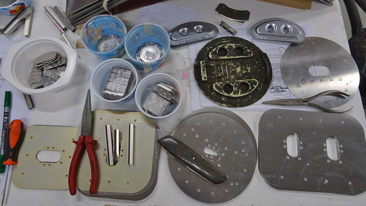
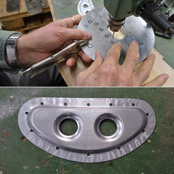
Hatch for Myrsky auxiliary fuel tank rack is being madeLauantai 8.12.2018 - Member of Tuesday Club There are several different inspection, maintenance and operation hatches on the wing of VL Myrsky II. There are four hatches for the auxiliary fuel tank racks which also served as bomb racks, two on either side. The hatches are made of 1 mm aluminium sheet. They are round and 17,5 cm in diameter. In the middle of each hatch there is an elongated lock disk, which has a spring and can be pushed open and closed using a finger.
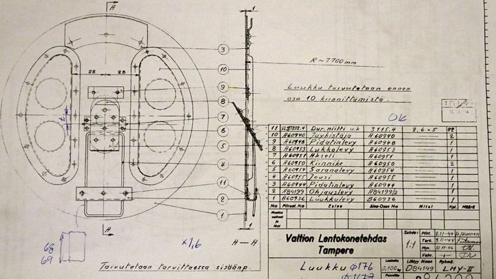
The operation hatches of the auxiliary fuel tank rack have a complicated structure. Fortunately, the Tuesday Club team had a detailed original construction drawing for making the hatches. The drawing has been dated in November 1944, so it is from the time when the Myrsky planes were in production. Also one original auxiliary fuel tank rack hatch had been found. Other original hatches are not available.
The drawing on the auxiliary fuel tank rack hatch illustrates well how detailed drawings have been made even of the smallest parts when the Myrsky was designed. The drawing describes in detail the construction of the hatch and its parts, 12 of them in total. 42 rivets are needed when the parts are assembled together.
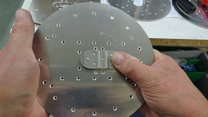
When the team started making the hatches for the Myrsky wings, billets for all the different hatches were cut from 1 mm aluminium sheet. Some of the hatches are round, some rectangular. A laser cutter was used for cutting the hatches. The exact shape and size of each hatch was programmed for the laser cutter and the data was fed into the cutter using a memory stick. The holes for the rivets were also cut using the laser, several rivets are needed to fasten the parts together. The advantage of the laser cutter is that the outcome is exactly according to the original drawing.
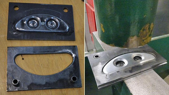
The first task of the team was to make the hatches for the auxiliary fuel tank and bomb racks. Six hatches are needed, two for each side and two for the Myrsky test wing. The first item to be made were the crescent-shaped stiffeners on the inside of the hatch. Twelve billets, slightly larger than the final stiffeners, were cut from 1 mm aluminium sheet. Two holes were cut according to the original drawing for making the stiffener lighter. For pressing the billets into shape, female and male pressing moulds were made. The billets were pressed into shape between the moulds.
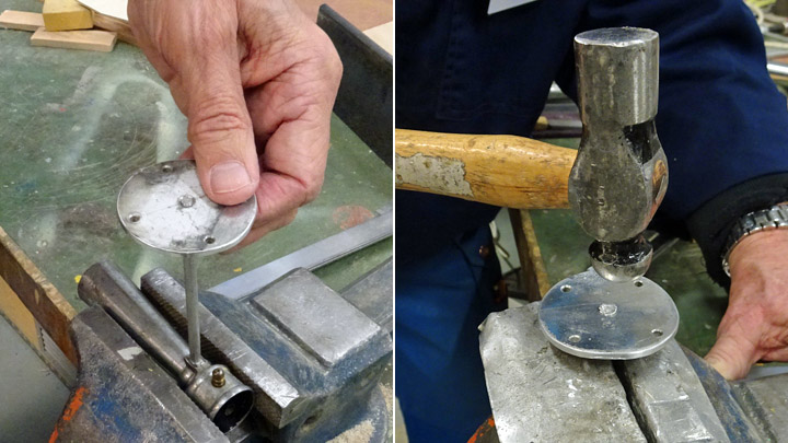
The extra “skirt” was cut off.
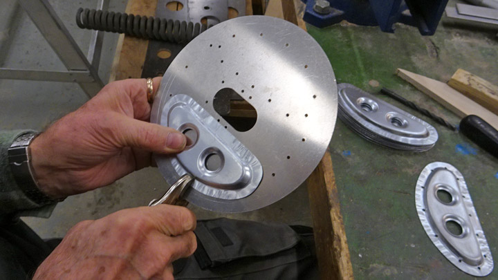
The following task was to drill rivet holes on the edges of the crescent-shaped plates, so that they could be riveted on the inside of the hatch. The stiffener was clamped tightly on the inside of the hatch plate, exactly on the right place. Then the hatch plate was turned around and the rivet holes for fastening the stiffener, already laser cut on the hatch, were marked using a marker pen.
The holes were drilled along the edge of the stiffener. Soon all 12 stiffeners were ready to be fastened on the hatch plates.
Another Tuesday Club team was working on the lock disks which will be placed in the middle of the auxiliary fuel tank hatch. The parts of the lock disk were riveted together and the lock disk was preliminarily placed into the opening in the middle of the hatch. A lot of work will be needed before the six auxiliary fuel tank hatches are ready, not to mention all the other hatches, which are at the billet stage. |
|
Avainsanat: aviation history, restoring, old aircraft, VL Myrsky II, MY-14 |
Ilmailumuseot.fi - Aviationmuseums.fi