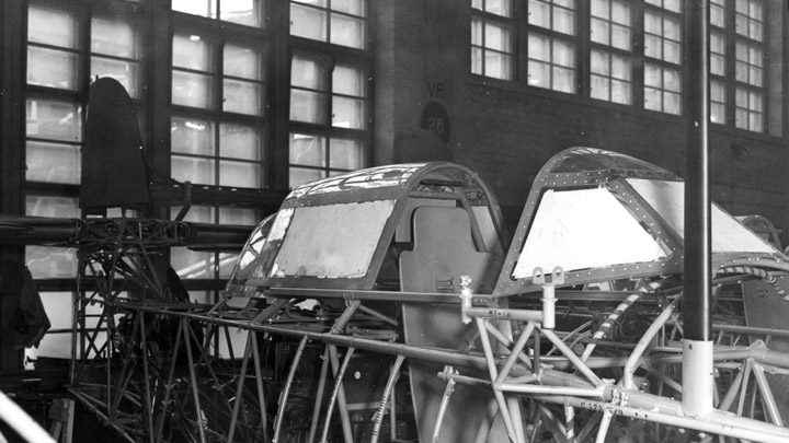
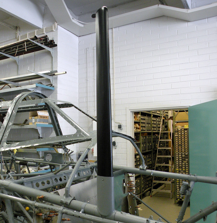
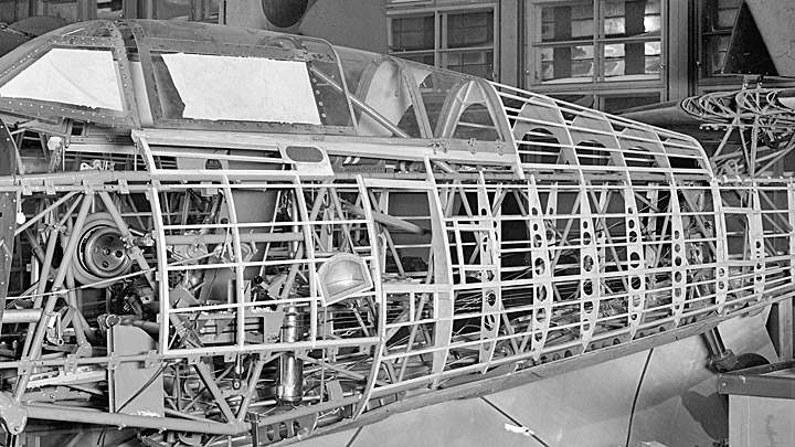
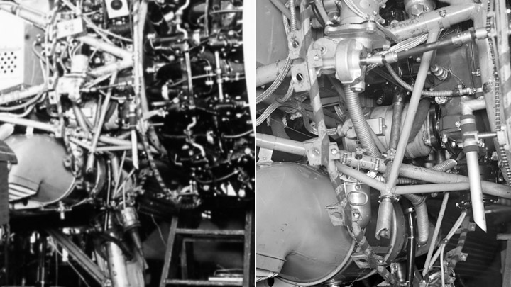
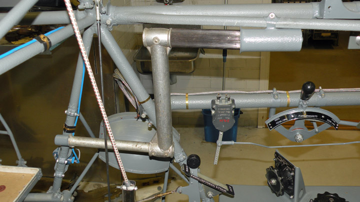
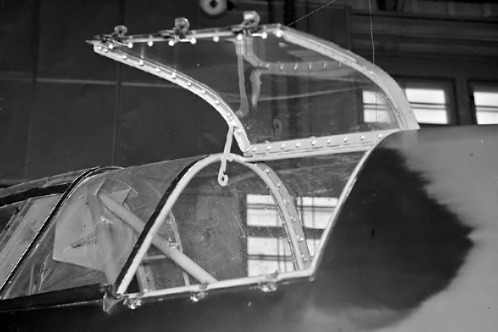
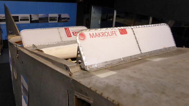
VL Myrsky has wooden aerial mastTiistai 18.7.2017 - Reino Myllymäki The aerial mast is on the right side of the front fuselage. The aerial cable is drawn between the mast and the vertical tail. The aerial lead-in is in the rear part of the canopy aft glazing.
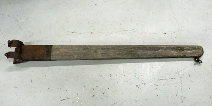
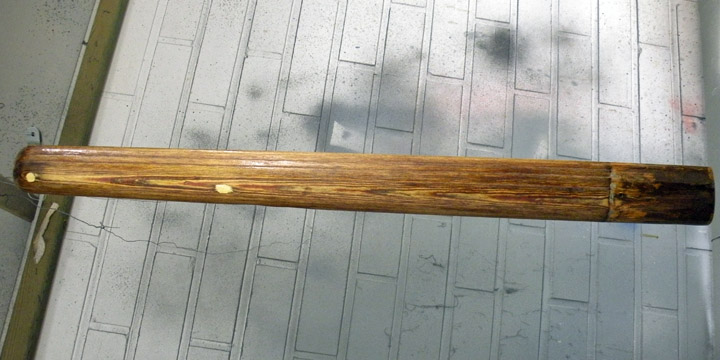
It is hard to imagine that the material of the aerial mast is wood. Exactly, the material is the laminated veneer lumber made from birch veneer and Bakelite.
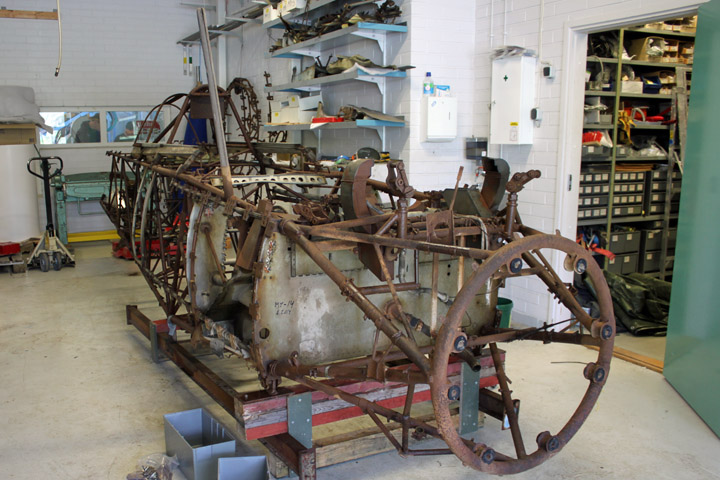
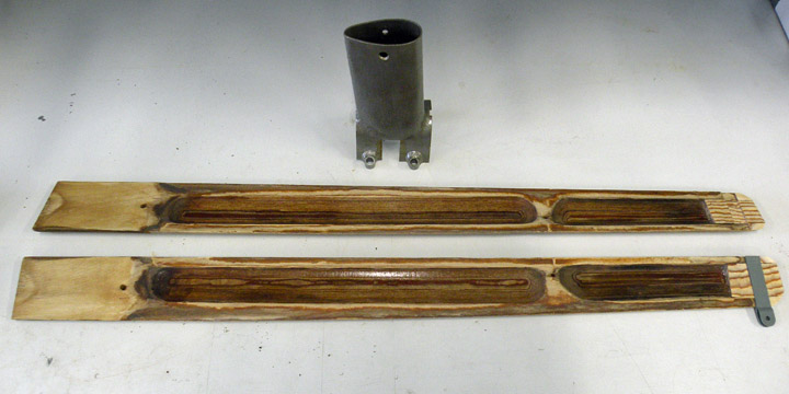
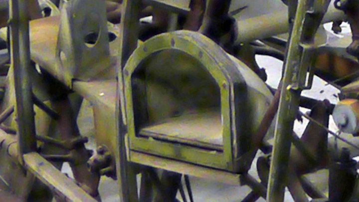
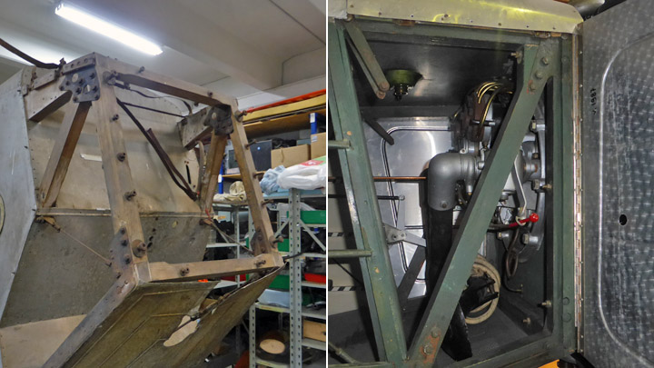
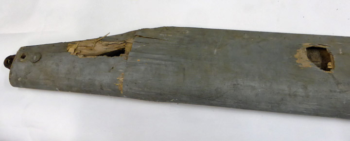
The aerial mast of the MY-14 has survived. OK, without painting and now almost splitted. The mount for cable was corroded as well as the root bracket.
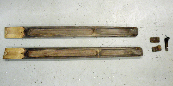
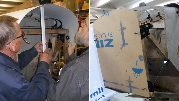
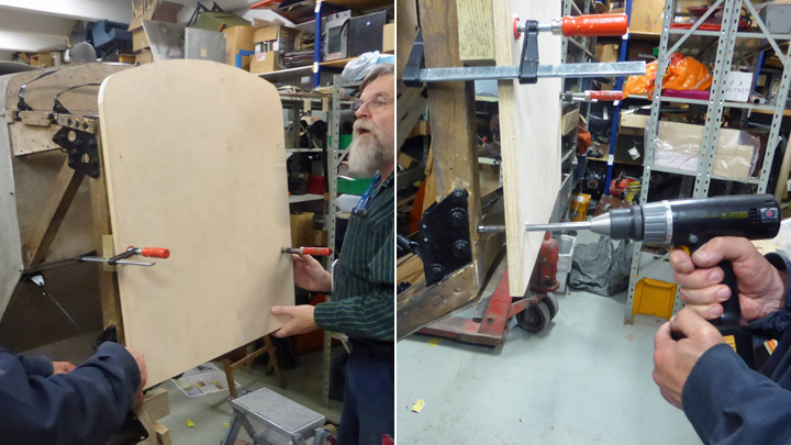
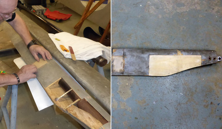
The restoration of the aerial mast was started by straightening the joint surface between halves by planing. The wooden filling block of the top of the mast was renewed according to the drawing and the original part.
The cross section of the mast is like a drop. The mast has been lightened by making two cavities to both halves. There is none wirings and therefore the only one reason for cavities is lighten the weight. The cavities were cleaned and lacquered by Isotrol.
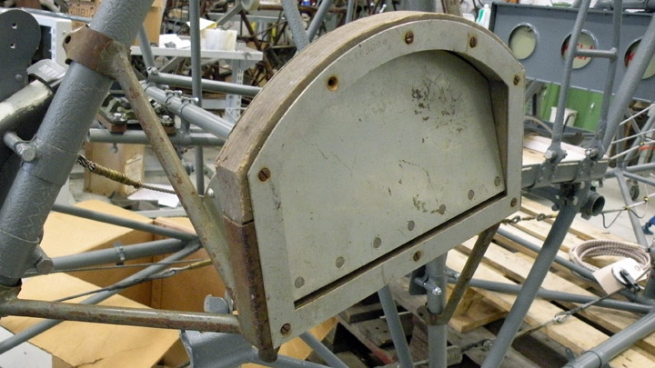
The mast halves were glued together by an epoxy resin. The outside of the mast was cleaned and lacquered. The cable mount was renewed according to drawings and the original part. The original root bracket was blasted by glass balls and lacquered. After that, the mast was fixed to the bracket by a slot-headed screw look like the original.
According to the remaininig paintings, the aerial mast has been painted first completely gray and after that the wooden part has been painted to black. The restoration work followed that observation. The result looks like the aerial mast in old photos.
In addition to propeller blades and the frame of the boardin step, the aerial mast is the fifth original wooden part of the MY-14. Historical photo: via Kalevi Keskinen, others: The Finnish Air Force Museum. |
|
Avainsanat: aviation history, restoring, old aircraft, VL Myrsky II, MY-14 |
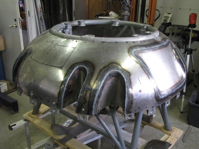
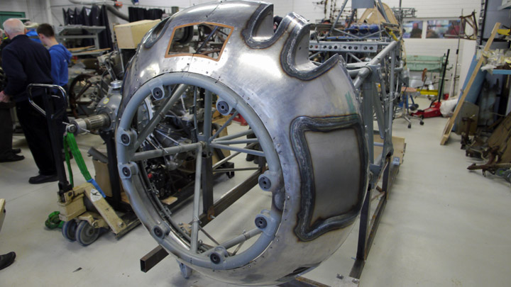
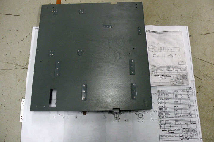
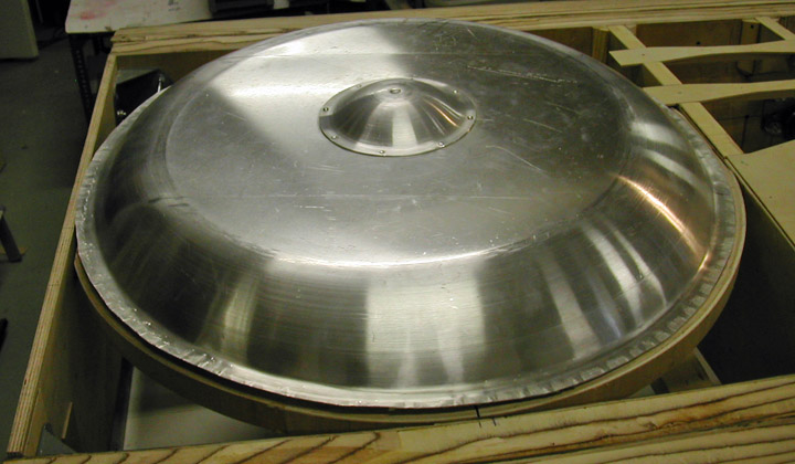
Potplate and engine for MY-14Lauantai 15.7.2017 - Reino Myllymäki VL Myrsky II has a 0,75 mm thick domed steel plate between the engine and the engine stand. It directs air stream and protects fuel tank, cartridges and cockpit against fire. There is no remaining pot plates of VL Myrsky II. Therefore it has to be made. Antero Flander from Flanco Oy in Rautalampi started the work. He made the potplate according to the drawing E61328. Some finishings were lacking but all parts and markings concerning needed cuttings included to the delivery.
There is one blog about pot plate: 13.3.2016. The pot plate was finished at the Finnish Air Force Museum workshop to correspond to the report for amendment number C302 and drawing E61328-I. According to the repair description dated October 30th 1944 the top of the pot plate of the MY-14 has converted to detachable. The pot plate has been cut in two places and a hole was cut for the carburettor air intake. Needed holes for screws were drilled and the seams were strenghtened by strips. The flanged nuts were riveted. The edges of the hole for the carburettor air intake were strenghtened by strips and equipped with a leather border.
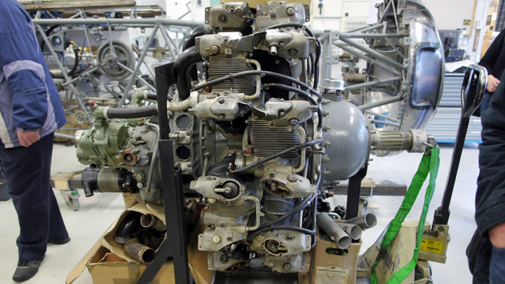
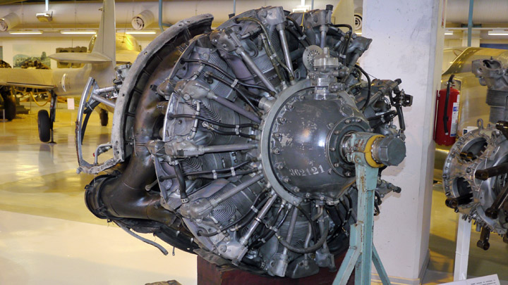
The engine stand was otherwise usable but the vibration observers were too poor and the bolts were disappeared. The barrels of the observers could be restored. The vibration observer rubber of the VL Myrsky II is equal to one used in the Fokker D.XXI with Twin Wasp Junior engine. However, the hole for bolt is bigger. By using an original part as a model, a drawing has benn made and Korja-Kumi Oy in Tampere manufactured new rubbers according to the drawing. The barrels were restored but needed bolts, nuts and washers were bought from a hardware store. A STW C3 engine has been installed to the stand. The STW C3 is a Swedish-built copy of the original Pratt & Whitney R-1830 SC3-G engine. The weight of the engine was 653 kg and a truck was needed in the installation work. Firstly, the project tried to acquire a pure SC3-G engine for the MY-14. Although at least 127 engines were bought to Finland, none was survived! An alternative S1C3-G engine has been in Douglas DC-3 passenger plane and stored years at the Finnish Aviation Museum. During the fall 2016, a second alternative has been found: STW C3 of the Saab B 17A target tug aircraft.
STW C3 engine in the workshop of the Finnish Air Force Museum. "I thought during last winter, that STW C3 is the most authentic engine for MY-14 in Finland", said conservator Harri Huopainen from the Finnish Air Force Museum. But the engine was not complete and needed a lot of work.
The engine of MY-14: a S1C3-G engine from the show of the Finnish Air Force Museum. Due to that, the former DC-3 engine type S1C3-G from the show of the Finnish Air Force Museum has been chosen for the MY-14. The only difference between SC3-G and S1C3-G is the rated altitude of maximum boost. According to FAA´s flyer A-699, the SC3-G can be converted to S1C3-G by changing the fuel and by adjusting the ignition timing. So, the fixed engine needs to be removed... First photo: Antero Flander, others: Reino Myllymäki. |
|
Avainsanat: aviation history, restoring, old aircraft, VL Myrsky II, MY-14 |
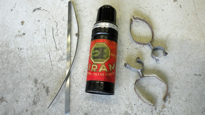
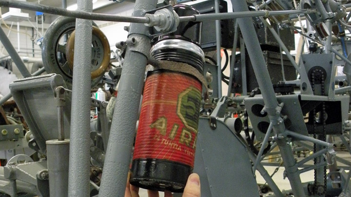
Why there is thermos bottle in structure of Myrsky?Torstai 13.7.2017 - Reino Myllymäki If you look at the old photos of the VL Myrsky II, you can find a thermos bottle in the middle of the studs, wires and pipes. What is the function of that Airam thermos bottle?
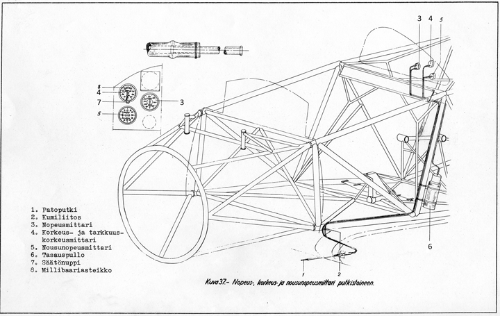
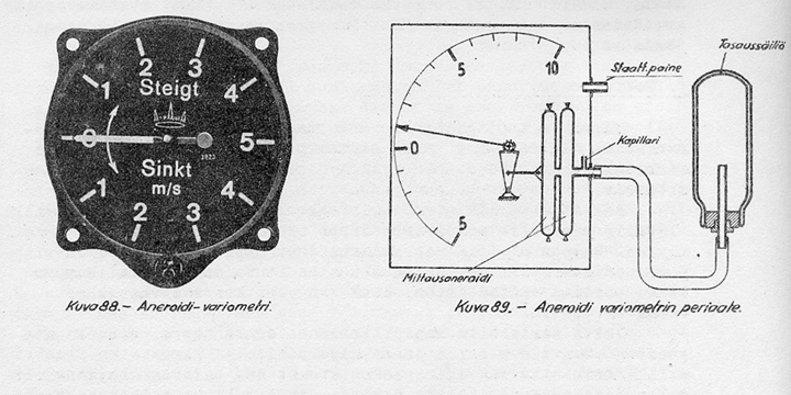
The Airam thermos bottle is a balance bottle of the variometer. The variometer get the static pressure from the pitot tube as the speed and altitude meters.
When the aircratft is climbing, the air pressure lowers and there is a growing pressure difference in the variometer. The variometer does not meter the pressure difference directly since the comparison pressure comes from the balance bottle. The pressure of the bottle is changing slowly and therefore the difference is different than theoretically it should be.
The balancing bottle is a standard Airam thermos bottle. The capacity is 0,44 litres including the 0,5-1,0 meter long capillary pipe.
The variometer has has 8 to 10 second delay. If the climbing changes rapidly to the lowering, the variometer can indicate still climb during the start of the sinking. Otherwise the variometer indicates the climbing and the lowering and their speed.
The original Airam balancing bottle has been donated to the project by the Airam. The bottle's place is above the map box in the left side of the cockpit. So, it easy to understand if somebody presume it pilot´s hot chocolate bottle! Historical photo: The Finnish Aviation Museum. Other photos: The Finnish Air Force Museum. |
|
Avainsanat: aviation history, restoring, old aircraft, VL Myrsky II, MY-14 |
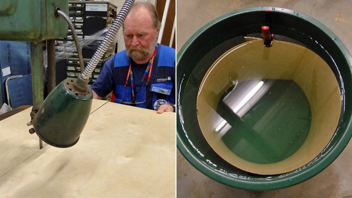
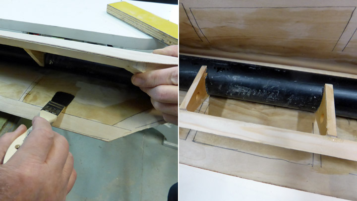
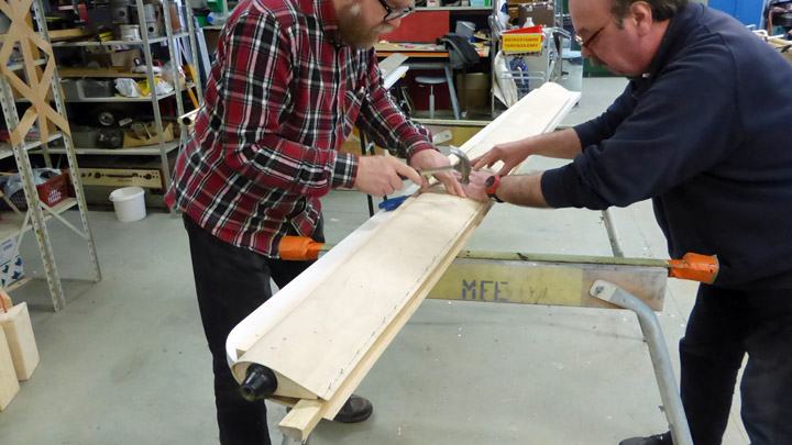
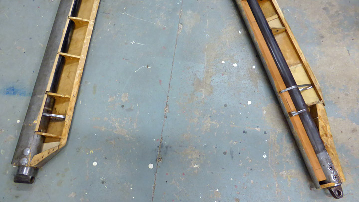
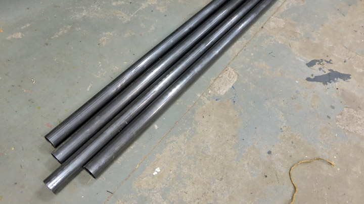
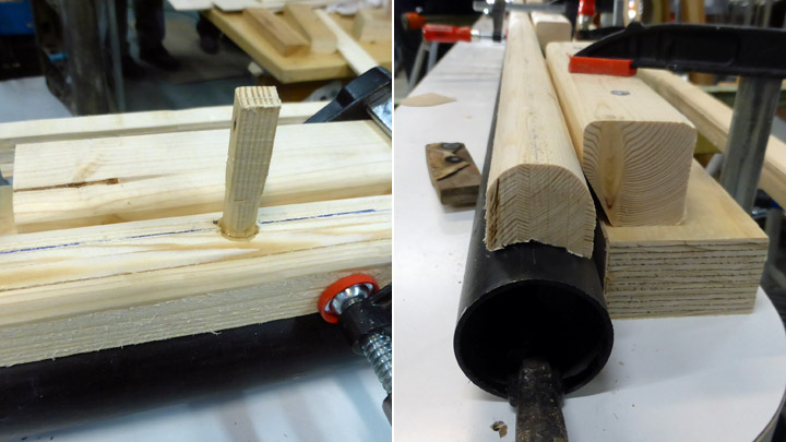
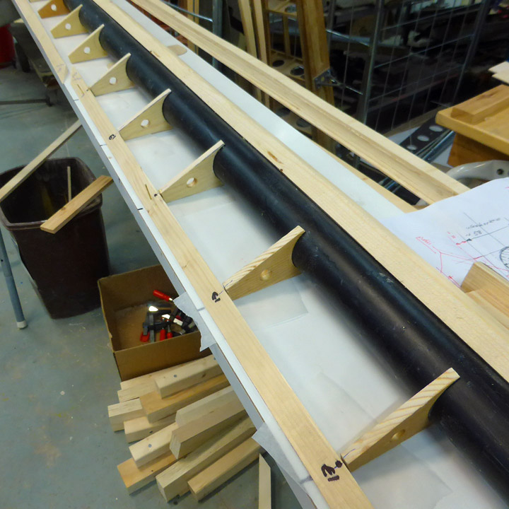
Wooden parts of ?Kurki? wing-struts madeMaanantai 10.7.2017 - Member of Tuesday Club The February blog covered the preparatory work for making the four missing wing-struts for the I.V.L. K.1 “Kurki”. The total number of wing-struts for the high-wing “Kurki” is six, three for each wing. Two original ones had survived at the Päijänne-Tavastia Aviation Museum at Vesivehmaa and they were brought to the Tuesday –Club for conservation, but the four missing ones we had to make. Work on the wooden parts of the wing-struts begun in February and by the end of June the wooden parts, including the struts plywood cover are in place ready for painting. But the metal fittings at the ends of the struts still have to be made. The struts main loadbearing part is a steel tube of 51.5 mm outer diameter. A wooden leading edge, formed from a 50x50 mm piece of wood is attached to the tube. The trailing part is made up of wooden ribs glued to a triangular wooden trailing edge. Profiled wooden end-caps were then attached to the top and bottom ends of the struts.
A close look at the damaged original wing-struts showed that they were covered with 1.2 mm thick plywood so plywood of similar thickness was used when covering the struts. As the total circumference of the strut is 37 cm, 39 cm wide strips, giving us a 2 cm working-allowance, were cut out of 140X140 cm plywood boards.
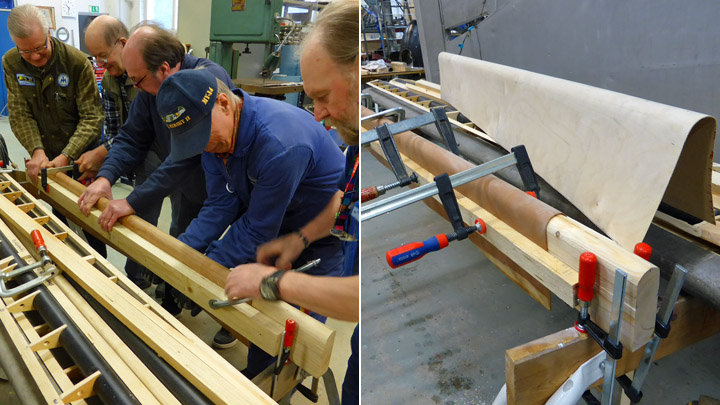
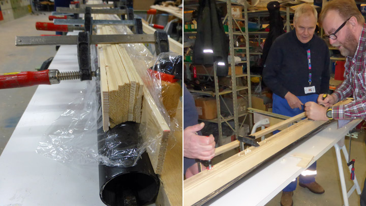
Before the covering-strips could be fitted to the struts, they had to be formed to the correct curvature to give a good fit. The forming was done by wetting the strips in water for some days, after which they were clamped to a wooden beam-mould that had bene worked to the same profile as the wing-strut. When the strips had dried they were released from the mould and found to have the correct curvature. As the length of the struts are 262 cm and 273 cm two butt-joined strips per strut were needed.
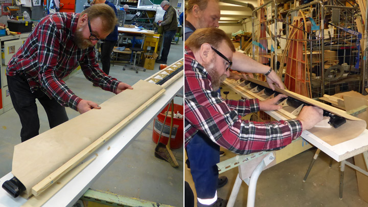
The covering of the first strut was begun by gluing the formed plywood-strips to the wooden leading-edge using Erikeeper-Plus adhesive and firmly clamping the strip using a strong lath of wood kept in place by three screws fastened through the lath and the strips into the wooden leading edge. Later the small holes in the leading edge made by the screws were plugged using wooden plugs.
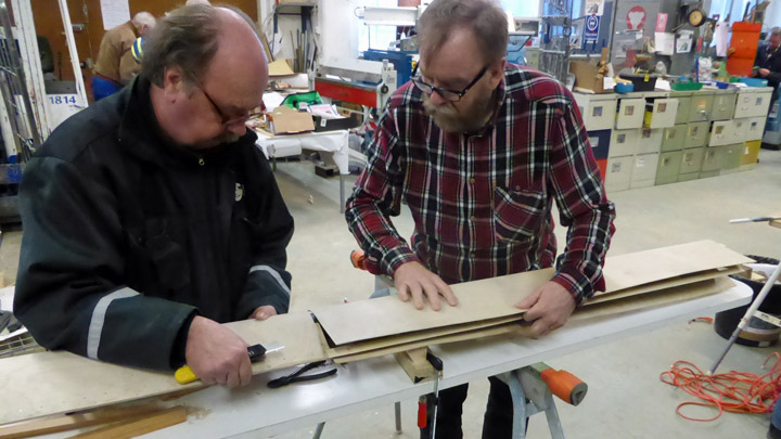
When the strips were firmly glued to the leading-edge the work of gluing them to trailing-edge ribs was begun, piece by piece. Before spreading the adhesive the positions of the ribs end the trailing edge were drawn on the inside of the strips. This done the rest of the inside was varnished using Le Tonkinos varnish. Before applying the adhesive we drilled small holes for the nails through the strips into the ribs and the trailing edge-lath to prevent any splitting when nailing the strips in place during the gluing. The sheets on the original wing-struts had also been nailed like this.
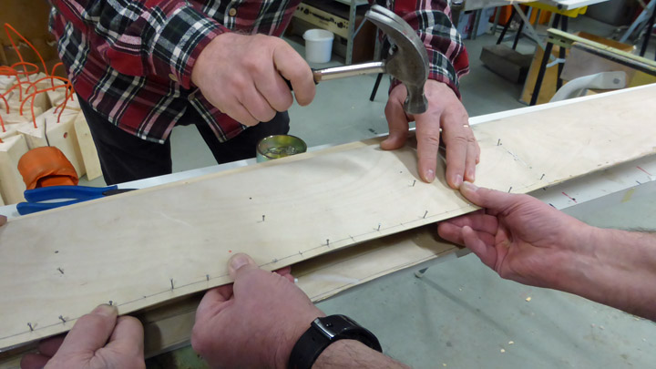
Now the adhesive was applied to the ribs and the trailing edge and the first strip pressed firmly against the ribs while simultaneously nailing it to the ribs and the trailing edge using 10 mm long nails. The heads of the nails were sunk into the plywood using nail punches.
First we tried to glue the strip to the trailing edge by pressing it into place between two wooden lathes. The result was not what we wanted as the strip did not set in place evenly, but left some “grinning” waves along the edge.
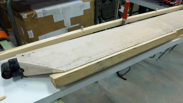
To ensure that the strip would make a good fit to the trailing edge a wooden lath the length of the strip was fitted under the trailing-edge and then the strip was nailed to the trailing edge and this under-laying lath with nails at 1.5 cm intervals, 1 cm from the trailing edge. Of course this also meant that the trailing edge lath was firmly nailed to the supporting lath.
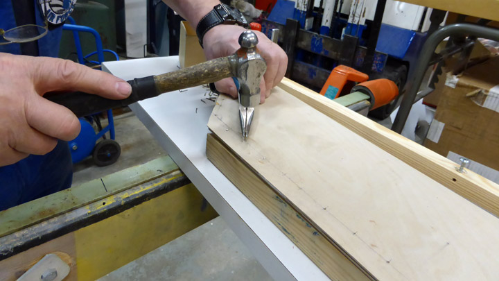
When the adhesive had set properly the supporting lath was removed with care, leaving the nail-tips sticking out. These were cut and sanded even with the surface of the trailing edge.
Midway on the strut the two plywood strips were joined using a butt-joint. To make the joint the small gap present was filled using a filler made of sawdust and glue. When it had dried the joint was sanded down until smooth and was now practically invisible.
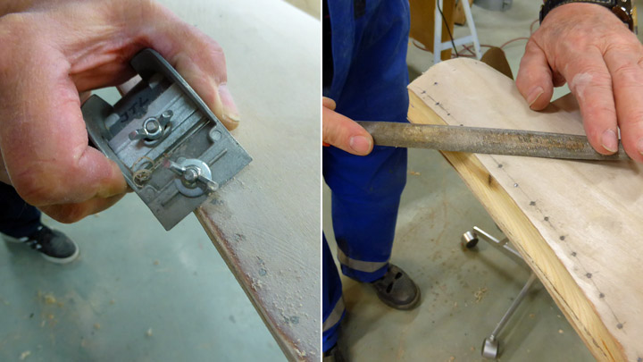
To finish off the work on the strut any excess plywood at the edges was planed off and the trailing edge of the strut was sanded to form a sharp edge. After this the cut ends of the nails securing the strips were filed down to the plywood surface and now the wood-work of the strut was done.
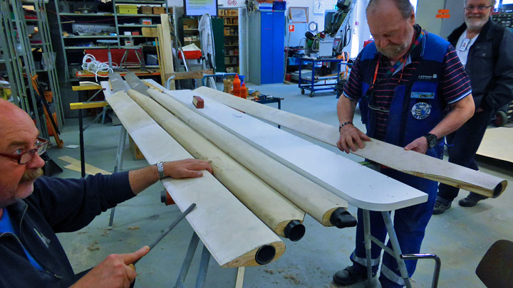
The other three new wing-struts of the ”Kurki” were made in the same way using the same ”manufacturing” materials and methods. When the metal fittings for the end of the struts have been made and fitted, it will be time to paint the wing-struts. This will be done using silver-bronze varnish in the autumn. |
|
Avainsanat: aviation history, restoring, old aircraft, I.V.L. K.1 Kurki |
Control column for MY-14Torstai 6.7.2017 - Reino Myllymäki The original control column of the MY-14 is not preserved. Only the rocker, balusters, the root and the wiring were left in the steel framework of the MY-14. All parts in the frame were corroded. Luckily, the surfaces of the sliding bearings were in good condition.
A control column of the VL Myrsky in the show in the Jämijärvi airshow in July 2015. Photo: Reino Myllymäki. The Finnish Air Force Museum had two incomplete control columns of the VL Myrsky. Another of them was restored wrongly. By using parts of both control columns, the MY-14 could get it. The Bakelite cover has been taken from the wrongly restored column. The firing button was found in the storages. The root block of the column was in better condition than the one in the MY-14´s frame and it was accepted to restoration. Otherwise MY-14´s original parts were accepted.
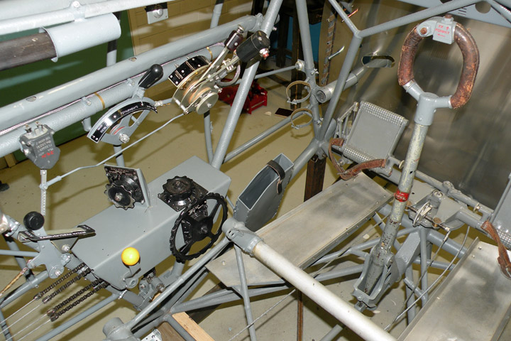
The MY-14 cockpit on June 20th 2017. The crank starter and the switch of the alarm buzzer on the left top. The propeller control lever and the throttle levers below them. The tail wheel lever, the trim control box and the map box at the bottom. The meaning of the brackets above the map box will be found from the next blog. Photo: The Finnish Air Force Museum. The parts of the mechanism were blasted by glass balls and painted separately. The stick of the control column was left unpainted and lacquered by Isotrol Klarlack only. The red help texts were repainted. The wiring renewing would demand the dissassembly of the riveting and therefore only the visible part was renewed. |
|
Avainsanat: aviation history, restoring, old aircraft, VL Myrsky II, MY-14 |
MY-14 got propeller control and throttle leversTorstai 29.6.2017 - Reino Myllymäki VL Myrsky II fighter has a VLS 8002 constant-speed propeller. According to name, the propeller keep the rotational speed by changin the blade pitch.
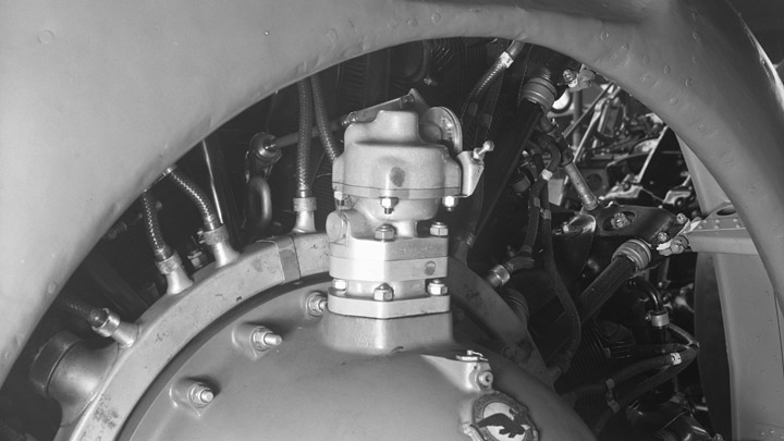
The object on the gear box is the constant-speed unit. Notice the quality of the leading edge of the NACA ring. Photo: The Finnish Aviation Museum. VLS 8002 in a propeller construction of the State Aircraft Factory. It has three wooden blades with Hamilton Standard 3 E 50 hub. The hub is not made by Hamilton: it is finished in Finland by using Swedish preform. The constant-speed unit is designed by Hamilton and it can change the blade pitch between 27 and 47 degrees.
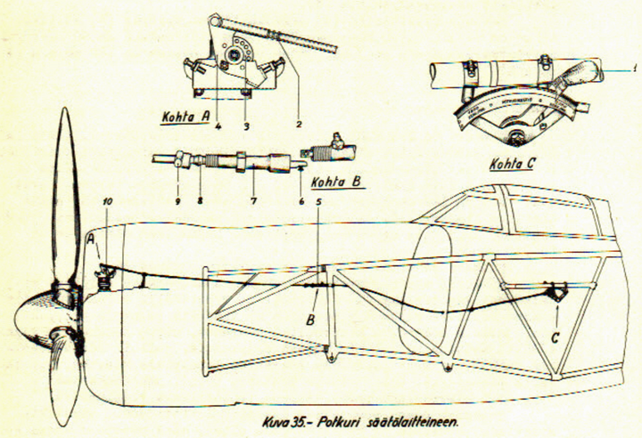
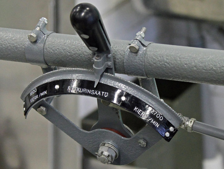
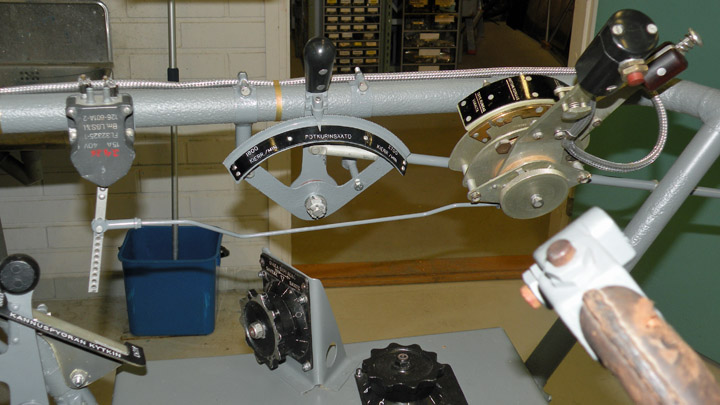
The blade pitch can be adjusted by a control lever in the cockpit. In front the blade pitch is decreasing and the rotational speed is increasing. In back vice versa. The lower pitch is used in the climbing and the higher pitch in the cruising. The propeller control lever of MY-14 was very corroded. The friction plates and knob were disappeared and the parts of the control levers of the MY-5 and the MY-5 had to be utilised. The steel parts were glass ball blasted and painted by Isotrol primer and paint. The duralumium parts were cleaned by oxalic acid. The new friction plates were lathed by using original Parkesin as a material. The Parkesin is trade mark of nitrocellulose called to "lusto" in Finland. In addition, the knob was lathed from black Parkesin and fixed by aluminum rivets. The original instruction plate of the control lever has preseved but in three parts. The material of the plate was Paxolin plate. Paxolin is fenol laminated paper. The paint was removed machanically and repainted by Miranol paint. The parts were glued together by epoxy resin and the result was fixed by aluminium rivets.
The casing pipe of the Teleflex wire of the propeller control system was cleaned by steel wool and some spacers' nuts were substituted by original parts. The steel casing pipes were so corroded that they had to be renewed. Since the engine is not yet installed, the Teleflex wire was not installed. In addition to that, the front part of the casing pipe system is still lacking. The throttle lever system consists of two levers. One controls the mixture and another is the essential throttle lever. There is a push-to-talk switch in the knob of the lever. In all, the throttle lever system is not a simple system since there are adjustable restrictors and a bar to enable the whole control range at the high altitude. All three throttle lever systems of the MY-5, the MY-9 and the MY-14 were in so poor condition that using an original spare part was a good idea. Unfortunately it was not complete. The throttle lever system was disassembled. The plywood friction plates were grinded until the system ran correctly. The steel parts were painted and a new knob were made. The push-to-talk switch was substituted by an original spare part. The wiring was renewed but the fastenind bands were original spares.
Finally, the levers were fixed. The result is excellent, isn't it? Histotical photo: The Finnish Aviation Museum. Other photos: The Finnish Air Force Museum. |
|
Avainsanat: aviation history, restoring, old aircraft, VL Myrsky II, MY-14 |
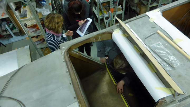
Passenger compartment chair of Kurki got original-like upholsterySunnuntai 25.6.2017 - Member of Tuesday Club The I.V.L. K.1 Kurki has already been under restoration for about a year in the Tuesday Club. It’s almost luxurious passenger-cabin has stood the test of time remarkably well. The upper parts of the passenger-cabin walls are upholstered in leather, while the lower parts have a textile covering (with a wall-to-wall carpet like material). The passenger-seat resembles a soft leather arm-chair. Or more precisely, has resembled, as its padding has gone AWOL during the long storage. Also missing is the ribboning that once framed the cabin-windows
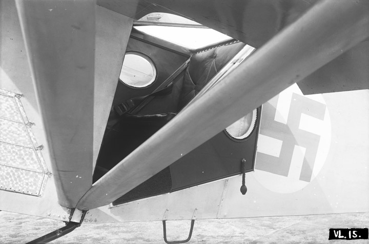
It seems that marketing reasons have been a driver when the Aviation Forces Aircraft Factory (since 1927 the State Aircraft Factory), operational on the Suomenlinna Islands in the 1920ies and -30ies, when designing the passenger-cabin. Originally the Kurki was designed with civilian use in mind, and later offered as a liaison-plane to the FAF. In the end it failed to convince neither civilian nor military customers and remained a single prototype. The already 90 years old original leather- and fabric wall-upholstery does not need any major conservation work. But the seat does need new padding. But what type of padding would be correct? Original drawings are not available so there we cannot find an answer. But luckily the photo-collection of the Finnish Aviation Museum has a photograph that helps us in the decision-making.
The photograph is of the Kurki with the door to the passenger-cabin open, giving a partial view of its interior. It shows enough of the seat-bottom and backrest to give us the confidence to proceed with the upholstering of the seat according to what shows in the picture. But who should do the work- though the Tuesday Club members master many a trade, upholstering is not one of them.
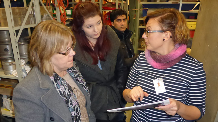
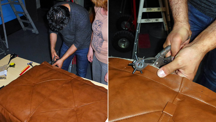
The solution to the challenge was found at the Tavastia Vocational College’s upholstery program. Since last spring, the fuselage and wings of the Valmet Tuuli III trainer, under restoration in the Tuesday Club, have been undergoing surface treatment and painting at Tavastia. Through our contacts at the college we got connected to its upholstery program, which joyfully accepted the challenge to let the students do this part of the project as a part of their studies. And so a number of Tavastia upholstery program students, led by their teacher Virve Juola came to the Finnish Aviation Museum to familiarize themselves with the Kurki and to do the necessary measurements of the passenger seat for the making of its new seat cushions.
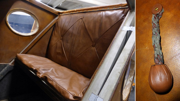
In late spring Tavastia informed us that the cushions made by the students was ready for installation and that they were coming to the museum to install it. At the Tavastia Vocational College the cushions had been made using 1920 type materials and work-methods. The top-side of the cushions were made of leather and the bottom side of linen-fabric. The seams in the seat-back cushions had been made using crossing seams as in the original one and using leather-covered buttons at the cross-points. At the top-side of the cushion a leather border for fastening the seat-back cushion to the seatbacks leather-covered top using press-fasteners had been sewn, just as on the original cushion.
At Tavastia horse-hair had been chosen to fill the cushions. Horse-hair is an old, traditional cushioning material that can stand moisture well and it does not mildew. The horse-hair cushioning was put into purpose-made linen bags that were sawn into the seat- and backrest cushions.
The old photograph also showed a hanging braided leather handle fastened to the inside of the cabin door, intended to enable the passengers to pull the door close when seated in the cabin. This had also gone amiss. The photo also showed that the free end of the braided handle was larger than the main part thereof, most probably there was a wooden ball inside the braid at its end. The new braided leather handle was made at Tavastia, with a wooden ball in its free end.
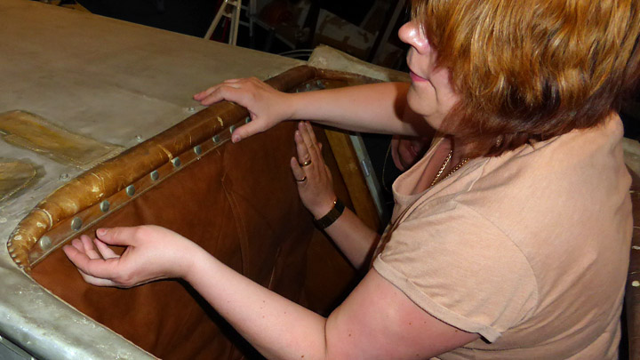
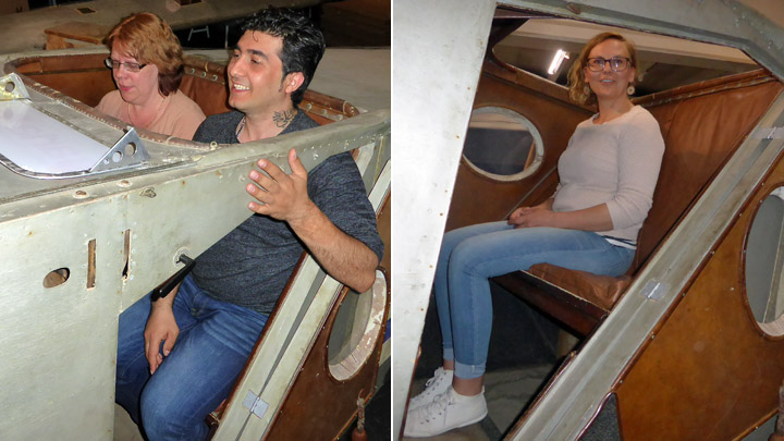
On Tuesday, June 6. was the big Kurki-day, when the upholstery students of the Tavastia Vocational College together with their teacher arrived at the Finnish Aviation Museum to install the seat cushions and the door handle into the Kurki passenger compartment. They fit like a glove! A bit of a surprise was the perfect fit of the press-fasteners into the existing original receiving parts from 1927 – what a measure of standardisation.
When the seat-cushions and the door-handle had been installed, it was time to test-sit the cushions and take “cold-types” of the “new original” Kurki passenger-cabin.
Our sincerest thanks to the students of the Tavastia Vocational College’s upholstery program and their teacher Virve Juola for their excellent contribution to the restoration of the I.V.L K1. Kurki passenger cabin. Historical photo: The Finnish Aviation Museum. Other photos: Lassi Karivalo. |
|
Avainsanat: aviation history, restoring, old aircraft, I.V.L. K.1 Kurki |
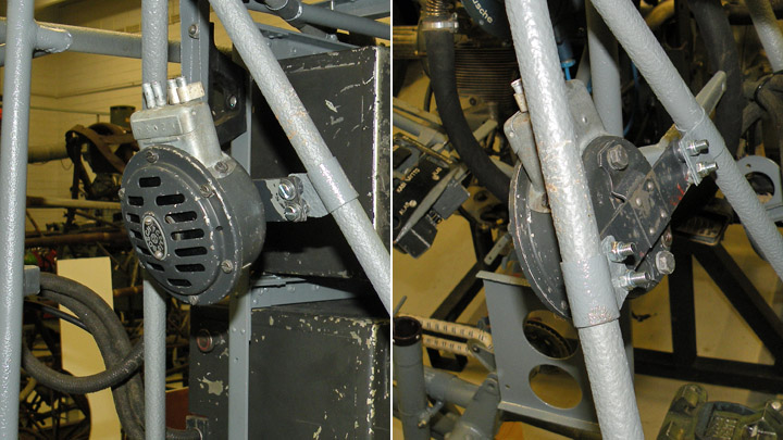
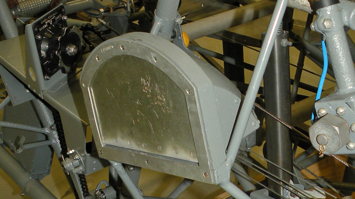
My-14 got something that she shouldn't haveTorstai 22.6.2017 - Reino Myllymäki According to the modification announcement dated late July 1944 at the State Aircraft Factory, the alarm buzzer of the landing gear should be substituted by the pilot light in VL Myrsky II. The maintenance instructions do not tell anything about the alarm buzzer. That is a warning system in order to warn when the engine runs idle and the landing gear is up. It was intented to avoid belly landings. The buzzer could be turned off by a switch. The alarm buzzer has disappeared but the bracket remained. According to that, the MY-14 had an alarm buzzer. It had not been changed to the pilot light during the repairs.
There were several alarm buzzers including brackets in the storages of the Finnish Air Force Museum. The best one has been restored for the MY-14. The orginial bracket was accepted but the mounting plate was renewed. The Siemens switch is an original spare part but the lacking press button was manufactured in the workshop. The alarm buzzer is located in the rear part of the cabin, front of the radio. Photos: The Finnish Air Force Museum. |
|
Avainsanat: aviation history, restoring, old aircraft, VL Myrsky II, MY-14 |
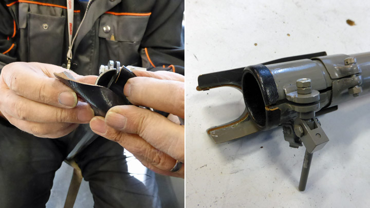
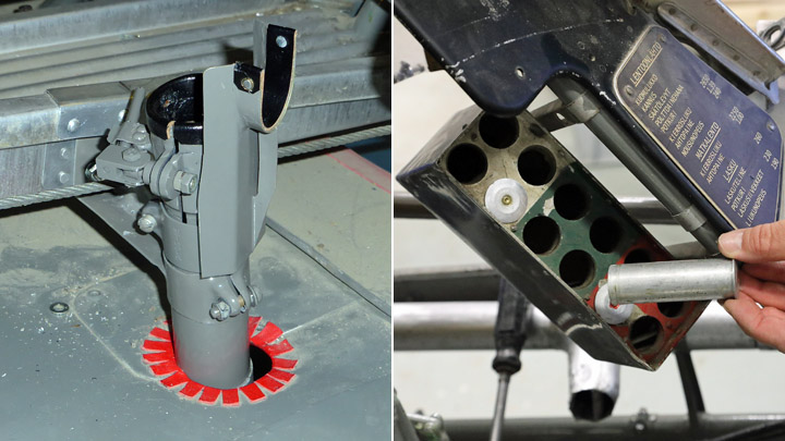
Valmet Vihuri VH-25 got flare pistol tubeTiistai 20.6.2017 - Member of Tuesday Club The cockpit of the Valmet Vihuri II (VH-25) under restoration by the Aviation Museum Society (Finland) is one step closer to completion when the flare pistol firing-tube going through the cockpit floor in the area between the pilots legs, was installed. Also an original flare pistol cartridge holder was fitted. Pilots who flew the Vihuri have told us that not every Vihuri was equipped with this tube, but at least our VH-25 now has one.
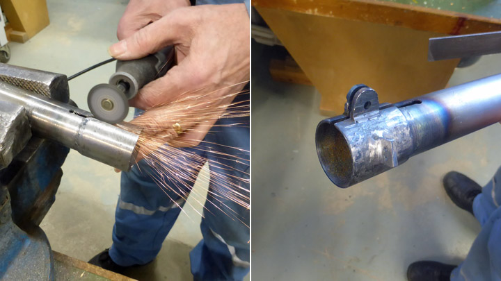
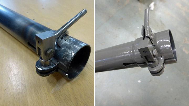
The flare pistol firing-tube was made according to original drawings. Its main part consists of a metal tube, with a piece of larger-diameter tube welded to its topside. Then slits were ground into this piece and a tensioning lever mechanism fitted. Tightening this tensioning mechanism decreases the tube diameter and thus ensures that the flare pistol stays in place in the tube when firing the pistol.
In addition to this, the tube is fitted with a small aluminium rack against which the flare pistol is placed into firing-position. Finally a leather padding was glued to the top-side of the tube and to the pistol rack. The unpadded metal parts were painted grey.
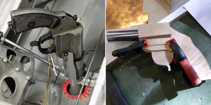
A hole for the tube was made in the floor of the front cockpit and the needed fastening to the fuselage frame was prepared. Before its final installation the firing tube was cut to its proper length. As a finishing touch some empty flare-cartridges were put in the cartridge holder on the right cockpit wall.
A “cold-test” of the finished firing –tube was done using a flare pistol from the Finnish Aviation Museum’s collection. However, this flare pistol will not be on show in the fuselage section of the Vihuri (VH-25) when it is exhibited in the museum. Instead, it will be replaced by a wooden “look-alike”. |
|
Avainsanat: aviation history, restoring, old aircraft, Valmet Vihuri, VH-25 |
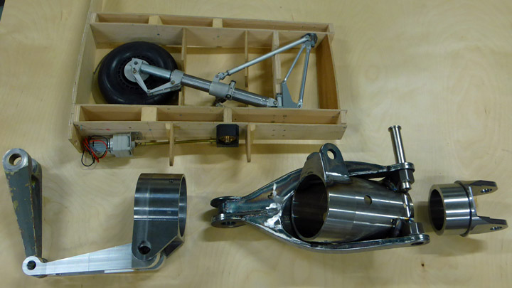
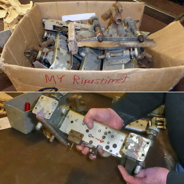
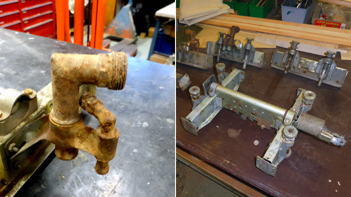
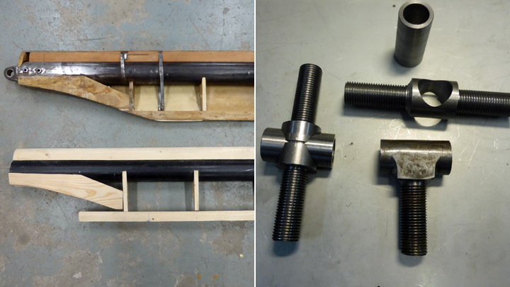
About the parts of the Myrsky landing-gear strutsTiistai 6.6.2017 - Member of Tuesday Club Though the test-wing under construction for the VL Myrsky (MY-14) by the Aviation Museum Society’s Tuesday Club is not yet ready for the installation of the main landing-gear parts of the landing-gear assembly have already been made and are ready to be installed. Unfortunately, only some original parts, such as wheels including brake mechanisms and parts for fastening the landing-gear assembly to the wing-spars, have been found. Thus, we need to have a number of the parts for the complicated landing-gear assembly manufactured. Luckily, we have most of the drawings needed for the manufacturing of the landing-gear parts available. Also, the landing-gear of the 1:4 scale Myrsky model made by our Myrsky-project manager Matti Patteri is proving most helpful. Patria Oy has taken the responsibility for manufacturing the oleo-struts. The Tuesday-Club’s Myrsky-project team has taken the responsibility for all other parts of the landing-gear. Thus, in addition to having the main responsibility for the wooden parts, the project team will also work on some metal-parts for the Myrsky.
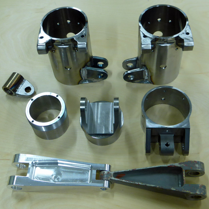
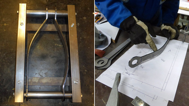
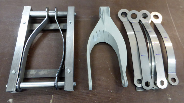
The topmost object is the landing gear of 1:4 model of Myrsky manufactured by Mr. Matti Patteri. This far, we have already finished the lower and upper forks of the scissor-joint that is a part of landing-gear retraction mechanism at the lower end of the oleo-strut as well as the axle beam components attached to the wheel-hub. Also the lug-tube that will go on to the middle of the oleo-strut and to which the forks of the landing-gear retraction mechanism as well as the rear landing-gear support strut will be attached. The upper fastening fork that goes onto the top end of the oleo strut has already been made.
Matti Patteri has been responsible for the design and guidance for the manufacturing of the metal parts including the laser-cutting as well as for the making of the jigs needed for the welding-work. Welding-work has also been performed at the Vantaa Vocational College Varia. The machining of some of the small metal parts has been done by Elmer Oy. |
|
Avainsanat: aviation history, restoring, old aircraft, VL Myrsky II, MY-14 |
One original wooden part to MY-14Torstai 1.6.2017 - Reino Myllymäki The VL Myrsky II restoration project has three steel-tube fuselage framework (MY-5, MY-9 & MY-14). They have lain on the ground below an open sky at least 20 years. Therefore wooden parts have decayed and steel parts have corroded. The project has got ready for substitute all wooden parts by reproduction ones.
There is boarding step located below the rear side of the canopy in the left side of the fuselage. The boarding step has a small hatch in order to keep the fuselage streamlined when the step is not in use.
The boarding steps of MY-5, MY-9 and MY-14 were all very corroded and the hinges of hatches were stuck. Luckily, one unused original spare part has been found in the storages of the Finnish Air Force Museum. One supporting tube was broken and there is a hole in an aluminium box.
The steel structure, the hatch with hinges and the plywood frame have been taken from the unused spare. The lacking tube was taken from the step of MY-14. It was welded to the steel structure.
The aluminum box was taken from the step of the MY-5. The metallic parts were blasted by glass balls and painted. The dented aluminium parts of the box and the hatch were corrected. The original screws of the plywood frame and box were substituted by equivalent new screws. It seems that MY-14 will have at least one original wooden part: the plywood frame of the boarding step. Historical photo: The Finnish Aviation Museum. MY-9 photo: Reino Myllymäki. Other photos: The Finnish Air Force Museum. |
|
Avainsanat: aviation history, restoring, old aircraft, VL Myrsky II, MY-14 |
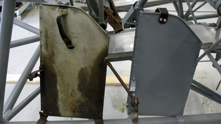
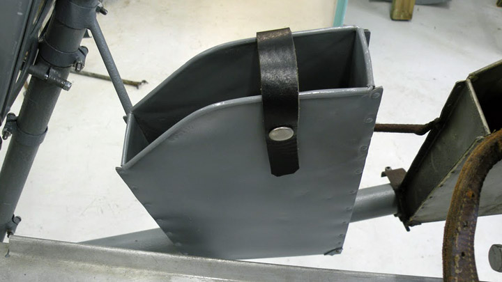
MY-14 got more equipmentKeskiviikko 24.5.2017 - Reino Myllymäki There is a metallic map box on the left hand side of the cockipit of the VL Myrsky II. Luckily we have an original part. The proper box is in a good condition but a little crooked and the leather strap was in poor condition.
The map box was blasted by glass balls, straightened, primed by Isotrol lacquer and painted to colour tone Ral 7045 (gray). The leather strap was renewed but the popper is original. The strap was riveted to the box. The box was fixed by renews bolts and screws to the cockpit.
There is a fresh air lever on the right side of the cockpit. The original was in a very poor condition. Luckily a quite complete original part was found from the storages of the Finnish Air Force Museum. Only the another fastening band was lacking.
The fresh air lever was blasted and painted. The help texts were renewed, too. The lacking fastening band was substituted by a repaired original part. The wire of the lever will be installed later. |
|
Avainsanat: aviation history, restoring, old aircraft, VL Myrsky II, MY-14 |
The engine-mounting cover-plate for the Kurki in placeMaanantai 22.5.2017 - Member of Tuesday Club When the fuselage of the I.V.L. K.1 Kurki was brought from the Päijät-Tavastia Avaition Museum to the Aviation Museum Society (Finland) Tuesday-Club for renovation it was a rather sorry sight. The tail was broken, the covering of the fuselage had holes and other damage, only bits and pieces of the windscreens remained, the metal parts were badly corroded and the engine mounting lacked both cover- and endplates.
During the year this fuselage has been worked on in the restauration workshop at the Finnish Aviation Museum and this work will soon be finished. In the Tuesday-Club the last months have been spent making the missing parts of the engine-mounting. The first part to be finished was the engine mounting plate, the work on which has already bene covered in an earlier blog-entry. Now we have finished the upper cover-plate and work on the side-plates is ongoing.
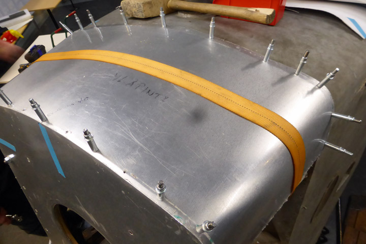
The work on making the top cover-plate started with making a cardboard model of it. Then a piece of 1.4 mm aluminium plate was cut to measure according to the cardboard model, after which the fitting of the aluminium plate to the engine-mountings top framework was begun. Working the aluminium plate proved to be a bit of a challenge as it was rather stiff and bending it into the required form took some doing. But we did it anyway, and did not try to do the work using a thinner plate.
When the plate had been formed into its nearly finished shape work was continued by fastening the front- and rear parts of the plate to the cover framework using Cleco-pins.
Thus the plate was held in place so that we could determine where and to what extent the plate still needed bending. It took a number of fastenings, removals and bending of the plate before it had been given its final shape.
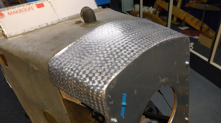
This done, the cover-plate was fastened to the engine-mounting framework using Cleco-pins. The forward edge was fastened to the top of the engine-mounting front-plate and the rear edge to the plywood cover at the joint of the engine-mounting and fuselage. Ca. 15 mm of the edge of the cover-plate was bent downwards/inwards to fit tightly to the plywood.
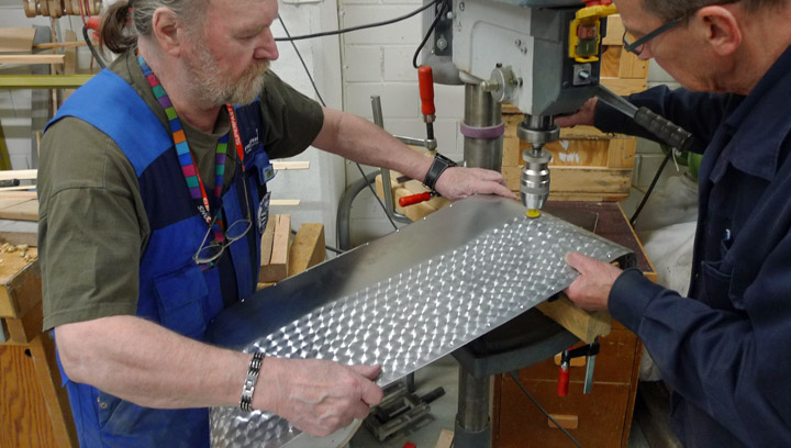
Before installing the top cover-plate, its surface was given a perlée finish using about 50% overlap.
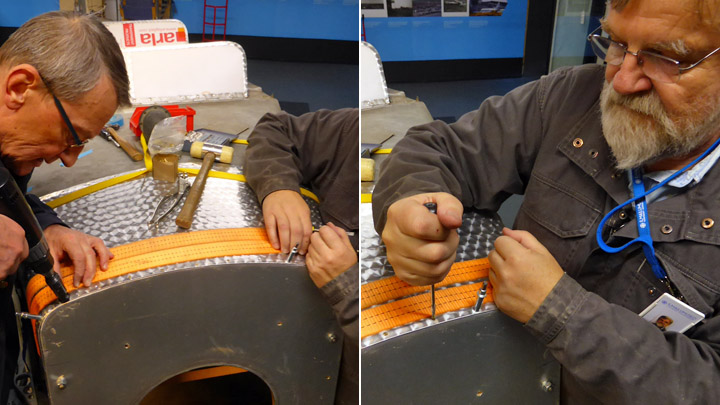
The final fastening of the finished cover-plate was done using slot-drive brass screws in the holes drilled for the Cleco-pins. As such screws were not readily available at the hardware stores, but such screws were obtained by special order from a specialist screw supplier and thus the top cover-plate could be secured in place in a proper manner. Using modern cross-drive or torx screws is not an option in a 1920ies aeroplane.
Beneath the top cover-plate there is space for the oil-tank of the Kurki´s Siemens-Halske Sh 10 engine. This means that there has been a hole in the top cover-plate for the oil filler-tube and cap. As the original oil-tank has disappeared and we have no drawings for it we were not able to determine the original location of the filler-tube. Thus we did not make any hole for the oil filler-tube. If we could find the original oil-tank, then we would fit it and make the needed hole in the top cover-plate. |
|
Avainsanat: aviation history, restoring, old aircraft, I.V.L. K.1 Kurki |
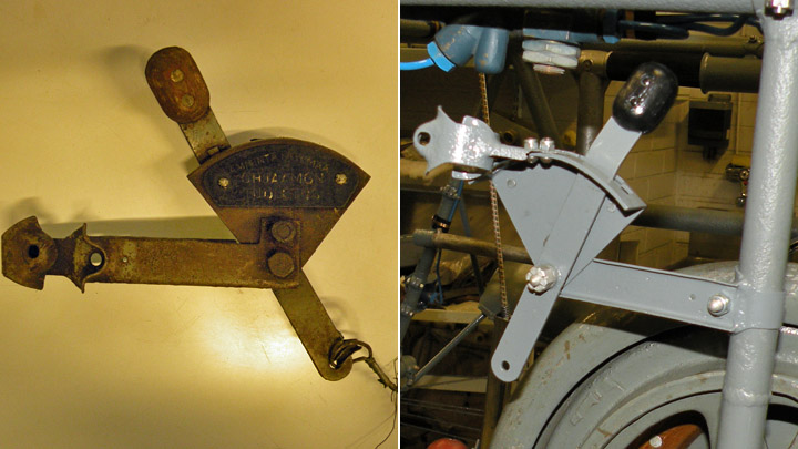
VL Myrsky has crank starterTorstai 18.5.2017 - Reino Myllymäki The Twin Wasp engine of the VL Myrsky II is started by an inertial starter. Normally, the starter is powered by an electric motor. When the starter has enough revs, the pilot pull the starter on and the engine will - hopefully - start. But the revs can be made by a crank starter, too. The extension rod of the crank starter is located to right side of the aircraft near the leading edge of the wing. The location of the joint of the extension rod and the crank starter handle is not easy to find in the photos. Most of the photos present the left side of the aircraft. And the camouflage painting is dark just there.
Left photo: Finnish Air Force Museum, right: Finnish Aviation Museum. When the aircraft has not coverings, the location is easier to find. The joint is supported by three tubes from three direction. The crank starter handle is located in the cockpit. It has place on the left side at the back of the tail wheel switch. The crank starter handle of the MY-14 has disappeared as well as MY-5´s and MY-9´s. The brackets have been spared. Luckily, an original crank starter handle of the VL Myrsky has been found from the storages of the Finnish Air Force Museum. Only cleaning was needed.
MY-14 got brackets from the MY-5 since they were in better condition. They were disassembled, blasted, painted and fixed. After that, the crank starter handle found an appropriate place. |
|
Avainsanat: aviation history, restoring, old aircraft, VL Myrsky II, MY-14 |
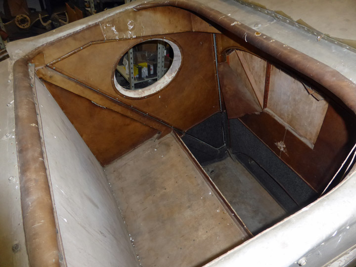
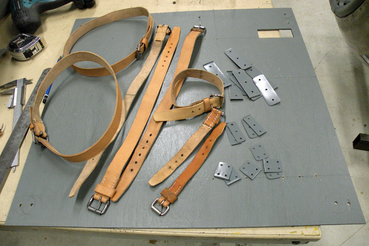
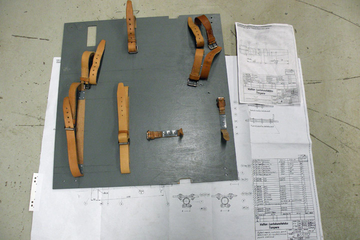
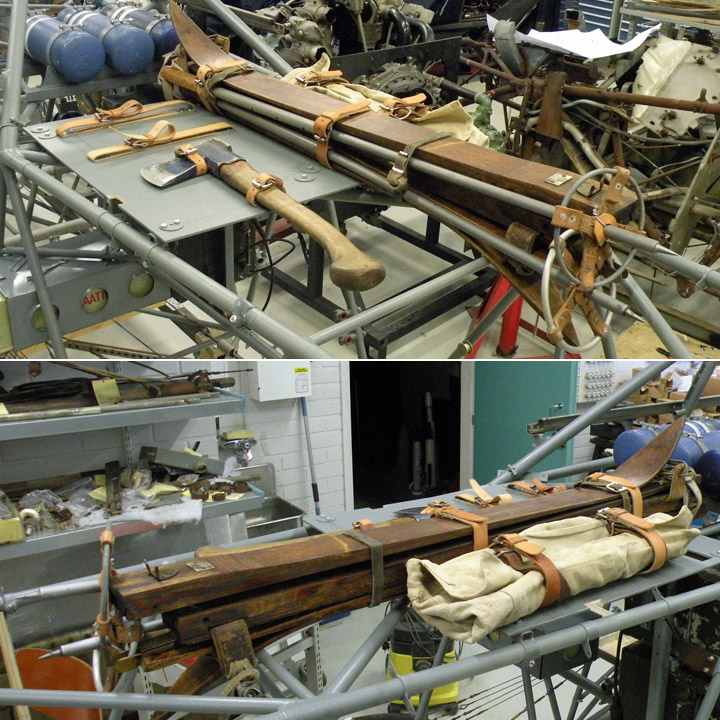
Emergency equipments to MY-14Maanantai 15.5.2017 - Reino Myllymäki VL Myrsky has the emergency equipment consist of a pairs of skiis, an axe, a K-ration pack and a toolkit. They are located after the cockpit and the oxygen bottles below the the canopy aft glazing. They were attached to the plywood plate by leather straps. The access to the emergency equipment bay was arranged by the glazing hatch.
The brackets of the plywood plate were existing in the all frames (MY-5, -9 and -14). Although the axe did not belong to the emergency equipment anymore, it had still the leather straps. Now the straps were disappeared except small parts between the plywood plate and mounting plates. All emergency equipments were disappeared.
The new plywood plate has been made according to the drawings. The brackets were blasted and painted. The screws were renewed.
The mounting plates of the leather straps were renewed. The leather straps were made according to the drawings and the preserved parts of the Fokker D.XXI (FR-137).
The leather straps were fixed to the plywood plate according to the drawings.
The pairs of skiis were restored and tared earlier. They were fixed to the plate. The axe was fixed tentatively since the axe and the toolkit did not belong to the emergency equipments during the wartime. The K-ration pack belonged but it has disappeared. The drawings of the K-ration pack were disappeared, too. The historical photo: The photo archive of the Finnish Aviation Museum. Other photos: The Finnish Air Force Museum. |
|
Avainsanat: aviation history, restoring, old aircraft, VL Myrsky II, MY-14 |
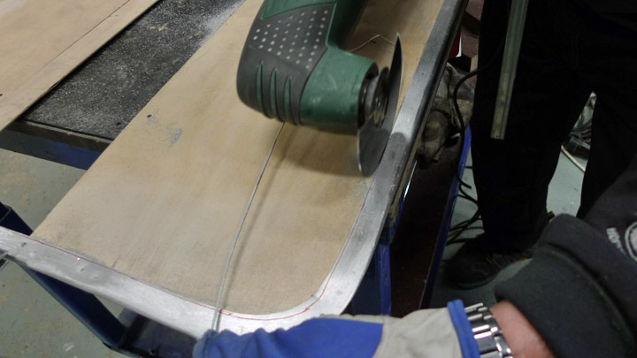
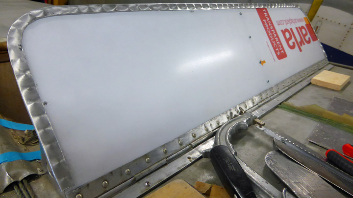
The Kurki windshields got their aluminium framesSunnuntai 14.5.2017 - Member of Tuesday Club During the autumn of 2016 the Tuesday Club fit new polycarbonate windshields to the I.V.L.K. 1 Kurki as the original celluloid ones had met their end during the long storage. In addition to this the three missing side-supports were made and installed. These were already covered in the December 2016 blog. However the making of the aluminium wind-screen edge-stiffeners was due this year. The original windscreens had been strengthened using a grooved aluminium edge-stiffeners. A few small pieces of the original ones had survived, and with these as a model we could make new ones. From the surviving pieces we could also establish that the edge stiffener of the cockpit windscreen was a bit wider than that of the windscreen of the passenger compartment. The reason for this remains unclear.
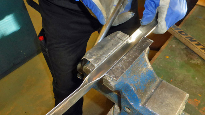
We started with the edge-stiffener for the cockpit windscreen. From a 1mm thick aluminium sheet we cut a piece with appropriate length and width. Then we made a 90 degree longitudinal bend to it using a sheet-bender. After this it was forced in a vice to make a groove. Now we faced the trickiest part of the job – shaping the groove-shaped piece to the shape of the windscreen edge with its rounded corners.
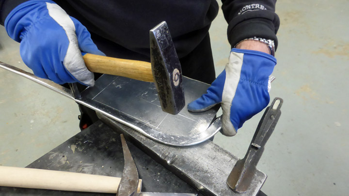
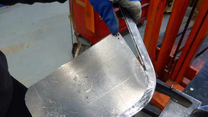
The edge-stiffener was hammered into shape against an inserted steel plate whilst simultaneously bending it to give it the proper curvature. Step by step we moved towards the final shape.
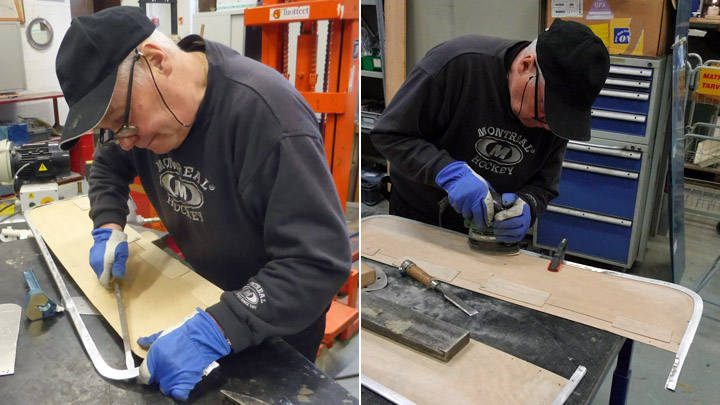
When the preliminary shaping of the cockpit windscreens edge-stiffener had been done we proceeded to make the passenger-compartment windscreen edge-stiffener. First we made it with the same width as that of the cockpit edge-stiffener. When both edge-stiffeners had been given their rough form their forming was tuned using plywood models of the actual windscreens, to which they were fitted and their fit stepwise refined until it was fine. Their tightness was ensured by squeezing to proper fit. When we were satisfied that they were OK, they were test-fitted to the actual windscreens. They fit nicely, and now the passenger-compartment windscreen edge-stiffener was cut to its final width.
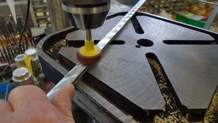
Now the edge-stiffeners were ready for finishing. First their surface was ground smooth and then polished. Then they were given the typical 1920ies perlée finish, as we were able to see traces of such a finish on the surviving original pieces.
The perlée finish was applied using a grinding-pad of 30 mm diameter in a drill-press. The pattern was such that it covered all of the surface. When the surface finishing was done, the edge-stiffeners were put in place on the windscreens and secured using small bolts.
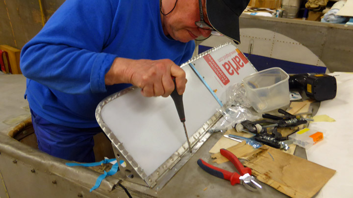
We still had to add the aluminium laths at the outside of the windscreens at the point of the triangular support brackets. Before securing the lathes in place using small bolts going through the windscreens we gave the laths the same perlée finish we had given the windscreen edge-stiffeners.
Now we could finally fasten the windscreens to the fuselage of the Kurki. The base-lathe of the foldable cockpit windscreen was secured to the fuselage using brass-screws (as it would not be proper to use modern torx or other modern types of screws when working on a 1920ies plane). The passenger compartment windscreen base-plate was secured to the plywood fuselage surface using 3x10 mm bolts as originally in 1927.
The windscreens of the cockpit and the passenger-compartment had now been finished – well not completely. The plexi-glass screens still had their plastic-film protective cover in place. They will be removed only when the work on the Kurki-fuselage has been completed and the I.V.L. K.1 Kurki returned to the Päijänne-Tavastia Aviation Museum in Vesivehmaa next autumn. In this way we can avoid damaging the windscreens during our continuing work on the Kurki fuselage. |
|
Avainsanat: aviation history, restoring, old aircraft, I.V.L. K.1 Kurki |
The engine-mounting front-plate for the Kurki has been finishedTiistai 25.4.2017 - Member of Tuesday Club The I.V.L. K.1 Kurki was brought for conservation without the engine-mounting front-plate and without the aluminium-plate side and top covers. The engine of the Kurki is fastened, or rather should be fastened, if we had an engine, to the mountings front-plate. Regrettably, we have no nine-cylinder radial Siemens-Halske Sh 12 engine available for this purpose. So if anyone knows that there is one available, hidden in a hangar or garage, please let us know. We´d be most happy to have on, even if just on loan. Engine or not, we decided to make and fit the missing engine-mount front-plate as well as the side and top covers.
As no plans of the Kurki have survived, we modelled the front-plate after the one on the VL Sääski (SÄ-122) on show in the exhibition hall I of the Finnish Aviation Museum. We did this, because both the Kurki and the Sääski were designed at the Aviation Forces Aircraft Factory at Suomenlinna in 1927 and both had a nose-mounted Siemens Halske Sh-12 engine. Thus it is most probable that they both had very similar or maybe even identical engine mounting plate and engine mounting. The engine mounting-plate of the SÄ-122 is made of thick plywood with the front part covered with an aluminium plate. Thus we chose 18 mm plywood for the plate, which was to be covered with an aluminium plate.
We started making the front-plate by establishing the form and height of the plate. This was done by attaching a piece of cardboard to model the missing engine-mounting top covering-plate. This allowed us to establish the form and height of the front-plate. Its side- and bottom measures were determined by the other parts of the engine mounting. When the rough measures of the front-plate established a sturdy model was made of cardboard. By making a model we wanted to make sure we had the correct form for the end-plate. The cardboard model was attached to the engine-mounting and some finishing modelling was done.
Using the finalised cardboard model a plywood end-plate preform was cut. The preform was then clamped to the engine-mounting to enable the correct positioning of the holes for the large-diameter fastening bolts going through the corners of the plate. When their position had been determined, the holes were drilled. Now the plate could be bolted in place and the holes for the other 10 fastening bolts could be drilled. After this we did some finishing work and sanding on the edges of the plate. Finally we made the round opening in the plate, enabling the installation of the engine. The size and position of this opening was calculated using the opening in the engine mounting-plate of the Sääski SÄ-122 as a starting point.
Before we begun to attach the aluminium cover-plate on the engine-mounting front cover we had to establish how this plate, the top covering plate and the side-plates attached to each other. From pictures of the Kurki we could determine, that the engine mounting front-plate was situated under the other. The top cover was installed atop of it and the side covers on top of this, covering both the top cover as well as the front-plate cover.
Covering the plywood front-plate was started by covering its sides using an aluminium strip some two centimetres wider than the edge of the covering-plate fit with the front and sides of the plate and bending the rest to go behind the plate. The strip was nailed to the sides of the plate using small nails and to the back of the plate using tacks.
Then the front of the plate was covered using 1.2 mm thick sheet aluminium. A piece was cut out the aluminium sheet to the shape of the front mounting-plate but to a size some centimetres wider than the plate. Thus the edges of the cut sheet could be bent to form a trough going over the edges of the plywood plate. The edges of the sheet were bent in a press, after which the holes for the fastening bolts were drilled. Now the aluminium covering sheet could be test-fitted the plywood cover-plate for the first time and the complete front cover-plate test-fitted to the engine mounting. It was a nice fit!
But we still had to make the hole, needed for the fitting of the engine, in the aluminium sheet. Thus the sheet was removed from the plywood-plate and a hole about one cm smaller than the one in the plywood-plate was cut in the sheet. Thus the edges of the hole in the aluminium-sheet could be chased into a collar over the edge of the opening in the plywood-plate. Now the final fitting of the aluminium sheet cover could be attached to the plywood engine mounting front covering-plate. This having been done, the completed covering plate could fastened to the engine mounting. |
|
Avainsanat: aviation history, restoring, old aircraft, IVL K.1 Kurki |
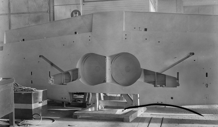
Wheel-bay cover fastening ring for VL Myrsky IILauantai 18.3.2017 - Member of Tuesday Club The landing-gear of the Myrsky retracts towards the fuselage with the struts and wheels retracting into bays between the main spars in the roots of the single, continuous wing.
On the top-side of the wing the wheel-bays are covered with slightly domed covers made of aluminium-plate. The covers are fastened with screws to a plywood ring forming the wheel-bay. Most of the wheel-bays, including their aluminium cover-plates remain hidden under the mid-fuselage covering the centre-part of the single wing, but a part of them are covered by streamlining-plates at the wing/fuselage joints.
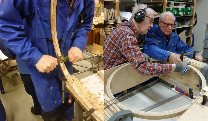
The aluminium-plate wheel-bay covers have already been made and now the making of the three needed cover-fastening rings are underway. One is needed for the test-assembly wing and two for the final wing that will be made for the MY-14.
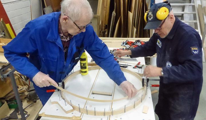
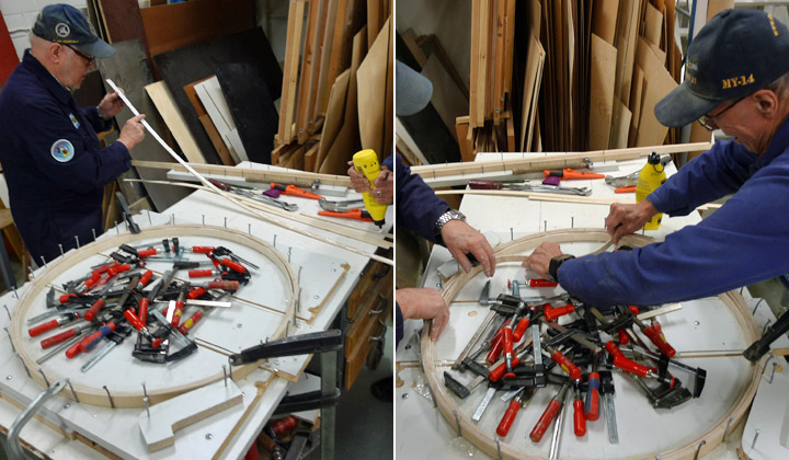
The making of the fastening-rings begun by making a mould. As on the drawings, a circle with a diameter of 750 mm was drawn onto a strong wooden board. Then sturdy nail were nailed along the drawn line with a spacing of ca. 2 inches. The fastening-rings will now be made by laminating eight layers of 3 mm thick 30 mm high, long plywood strips against the nailed circle, thus forming a 25 mm thick fastening-ring.
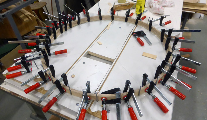
The first plywood-layer was tightened against the nails and onto it three more layers were glued using Erikeeper plus adhesive intended for outdoors use. The four layers were pressed tightly together using clamps. When the adhesive had dried properly, the clamps were released and the next four layer were added using the same procedure.
When the adhesive had dried the fastening-ring was removed from the mould and finished. It was then planed into a triangular cross-section with a top width of 25 mm. The other two rings will be made in the same way.
As the test-wing had been fitted into the assembly-jig and the part between the wing-spars had been assembled the test-fitting of the fastening-ring could be made. And it was a good fit. Also the aluminium cover-plate went into place nicely. The next step will be making and fitting the plywood landing-gear well walls in the wing. |
|
Avainsanat: aviation history, restoring, old aircraft, VL Myrsky II, MY-14 |
More than just building wing for VL Myrsky IILauantai 4.3.2017 - Member of Tuesday Club In the restauration of the VL Myrsky II (MY-14) the majority of the work done during the past couple of years has been on the wing. This might lead one to believe that the Tuesday Clubs part the whole project is only doing woodwork to make the wing. However, a lot of other types of work has also been done, as I have told you in earlier blog entries. This time I will cover some of the work on the following sub-assemblies; bomb-racks, the propeller-blade openings in the spinner and the landing-gear. Originally the Myrsky-fighter was not equipped with bomb-racks, but in 1944 a bomb-rack for a 50-100 kg bomb was fitted under each wing. These racks were also suitable for drop-tanks. For these there was a connector to connect the drop-tank to the planes fuel-system.
Fortunately parts for many racks have survived in the collections of various museums, so with some reconditioning done, we can fit the MY-14 with original racks. However, the racks found were partly disassembled, had broken parts, partly corroded or otherwise in need of reconditioning. So a selection of the best rack-parts were inspected, reconditioned and combined into complete racks to be fitted to the Myrsky´s wing in the Tuesday Club.
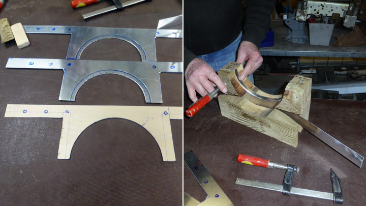
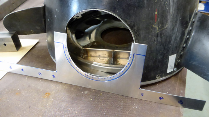
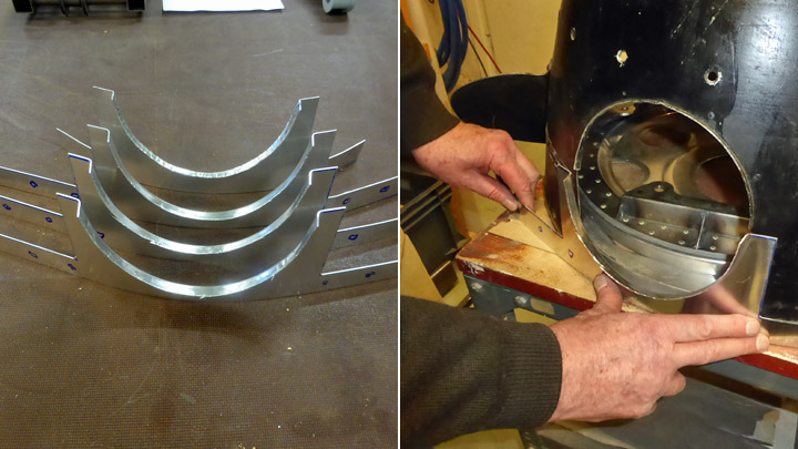
The spinner for the Myrsky has cut-outs for each propeller-blade and its regulator mechanism. At the base of the spinner the cut-outs are open so that the spinner can be fitted over the propeller hub and around the propeller-blades and fastened to the spinner’s back-plate.
On the spinner’s back-plate there is a protective sleeve made of aluminium that closes the back-part of the cut-out, thus creating a round cut-out hole and a closed back-edge on the spinner. No original sleeve has survived, so new ones have to be made. The missing spinner back-plate has already been made earlier in the Tuesday Club.
The making of the sleeves begun by cutting blanks out of aluminium sheet, according to the drawings. Then they were test-fitted to the openings. A wooden mould was made for the making of the profiled, bent edge of the cover-plate, and then the blank was fastened to the mould and beaten into shape. We still have to drill the holes needed for fastening the cover-plates to back-plate and then the cover-plates can be fit into position. The finishing work on the cover-plates is now ongoing.
No complete Myrsky landing-gear has survived to be fitted to the MY-14. Thus most of the landing –gear has to be made. Fortunately original wheels have survived and can in due time be fitted to our Myrsky. The reconditioning of their hubs and brakes has been covered in earlier Myrsky blog-entries.
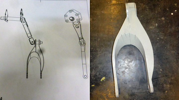
The Tuesday Club has neither the tools nor the skills necessary to make the needed new landing-gear oleo-struts. Patria, who is the major sponsor of the Myrsky restoration-project has taken the responsibility for getting them done. However, some landing-gear parts can be made by the Tuesday Club. Work on the landing-gear retraction-fork that connects to the oleo-strut is ongoing in the Tuesday Club. The hollow forks (one for each strut) consist of steel-ribs that are covered with steel-plates.
The work on the fork was started by making a full-size model to plans. In addition to this a metal jig was made for the assembly of the final forks. The wooden model makes interpreting the drawings easier and without a jig, the necessary dimensional precision of the retraction-fork cannot be achieved.
Work on the fork itself begun by cutting steel-plate blanks to measure to form the parts that will become the sides of the forks. Holes were drilled at both ends of the blanks after which they were bent to form and measure. Assembling the forks in the jig is ongoing. |
|
Avainsanat: aviation history, restoring, old aircraft, VL Myrsky II, MY-14 |
Repairing old and building new wing-struts for KurkiMaanantai 27.2.2017 - Member of Tuesday Club Two of the total of six wing-struts for the I.V.L. K.1 Kurki were found at the Päijänne-Tavastia Aviation Museum at Vesivehmaa. The found struts were the front- and the (diagonal) mid-struts. The struts were damaged, but repairable. However, a total of six struts are needed for the Kurki, three on each side, so four more have to be made. The existing struts will be used as templates for the new ones. As we have no models and no drawings of the Kurki have survived, we have assumed that they are similar in construction to the front-struts.
The two found wing-struts were damaged. Their plywood coverings had holes in them and they were partly rotted. The rotted parts must be replaced, and the holes must be mended. The rotted parts will be removed all the way to good plywood and new plywood will be put in in its place. Fixing the holes is underway in the well-proved Tuesday-Club manner – a square or rectangle is drawn around the hole and the cut is made in the plywood along the lines, the cut-out faulty piece is removed and replaced with a new piece of fresh plywood.
Having to remove the rotten wing-strut covering plywood was actually a blessing in disguise. Doing this, revealed the inner construction of the wing-strut. Thus we got the knowledge on how to make the missing struts. Removing the rotten covering plywood revealed that the main load-carrying part of the strut was a steel tube with an outer diameter of 52 mm. Attached to this was the solid-wood leading edge of the strut and the plywood-covered wooden ribs and the wooden trailing edge giving the strut its aerodynamic form. At both ends of the struts there were wooden support structures and a metal lug at each end for fastening the strut to the fuselage and the wing.
With the existing struts as models plans for the making of the four missing struts and a list of materials needed were made. As we were unable to source any steel-tube with the right diameter we had to settle for a 50.5 mm one. This was considered close enough for the purpose. Finding the necessary wood-materials for the making of the leading- and trailing edges was a piece of cake.
We started making the new wing-struts from the 3 m long steel tubes. The tubes were cleaned of their protecting grease and cut to measure. The tube for the front- and rear struts is 262 cm long and that for the mid-strut 273 cm. After being cut to measure the tubes were painted using black Isotrol varnish.
We decided to start by making the other middle strut. First the tube was firmly fastened to the purpose-built work-foundation. For the making of the wooden leading-edge we first cut 0.5 cm thick strips out of a piece of wood the length of the tube. These were glued together pushed against the tube, giving the back part roughly the shape of the tube and a rough leading-edge that was then planed and sanded to shape of the original leading edge.
The finished leading-edge was then fastened to the tube using four countersunk screws, with their heads sunk deeply into the leading-edge, after which the holes were plugged using wooden plugs. Thus the leading-edge was finished and it was time to tackle the trailing-edge.
From the original wing-struts we got the models for the trailing-edge ribs, of which we made some dozens to start with, and then we varnished the sides of the ribs. A strut will take 14-16 ribs. The needed ribs were fitted into place and glued to the tube using epoxy-adhesive – yes, we know epoxy was not used in the 1920’ies but… Then we made the wooden trailing-edge and glued it into place using epoxy-adhesive. Now the main parts of the wing-strut were done.
It was still lacking the solid-wood support-structures at each end as well as the metal fastening lugs. These are now being made in our workshop. We decided to make all the missing wing-struts up to this stage, before continuing with the finishing work and covering of them all. Work on the missing front wing-strut is already ongoing. |
|
Avainsanat: aviation history, restoring, old aircraft, I.V.L. K.1 Kurki |

Ilmailumuseot.fi - Aviationmuseums.fi