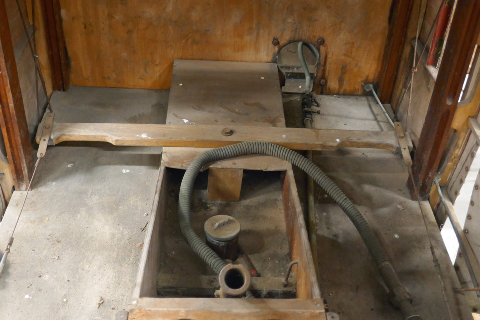
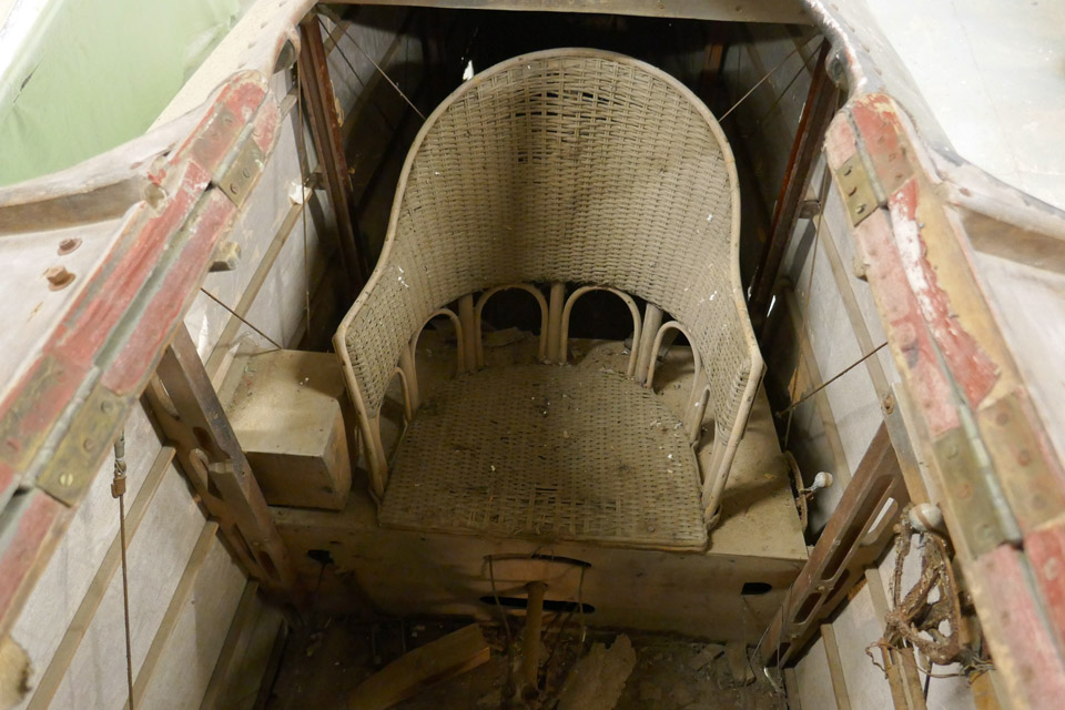
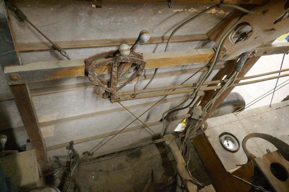
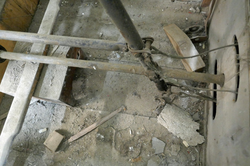
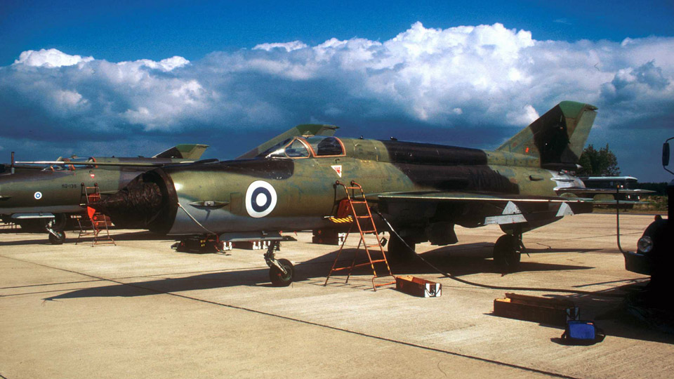
MiG-21BIS MG-111 cockpit is modified into experience simulatorSunnuntai 9.10.2022 - Tuesday Club member The MG-111 was the first MiG-21BIS fighter which was taken into use by the Finnish Air Force in 1978. This individual differed in certain characteristics from the BISes which the Air Force later received. In the first photograph the MG-111 is at the Oulunsalo shooting camp in June 1990. Notice the two little red Draken silhouettes on its vertical stabilizer, symbolizing the air victories over Drakens at the shooting exercise before the shooting camp.
Photo: Perttu Karivalo The MG-111 flew its last flight in 1993. In 1994 the aircraft was moved to the Finnish Aviation Museum to be stored. The last years the MG-111 stood outside, and in 2016 it was eventually cut to pieces as “canning material” on the museum yard. During the cutting process it was observed that the MG-111 was still in quite good condition. It is a pity that Finland’s first MiG-21BIS got an end like this.
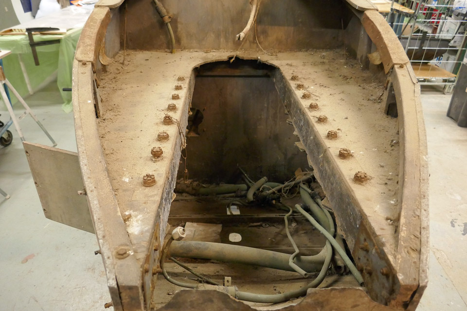
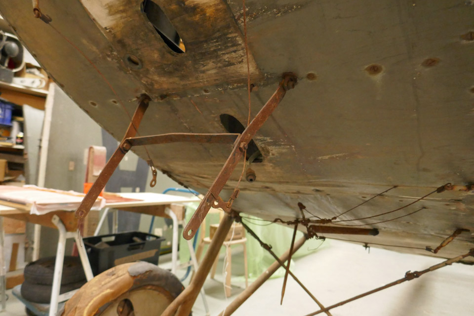
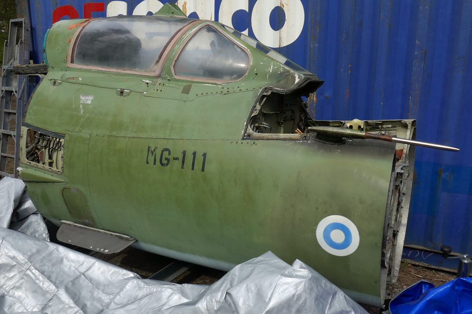
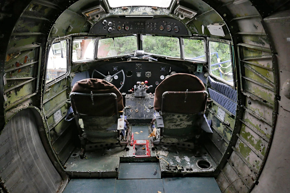
However, not everything ended up as raw material for cans. The fuselage was cut in front and behind the cockpit and the cockpit part was preserved, the plan being that the cockpit is modified into a MiG-2BIS experience simulator. Aviation Museum Society Finland owns the cockpit and its modification work into an experience simulator has started.
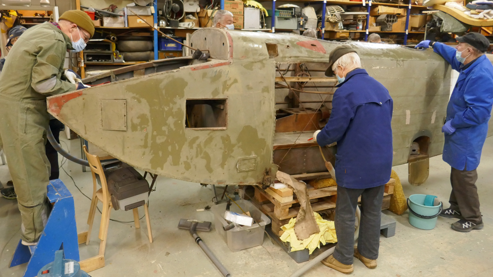
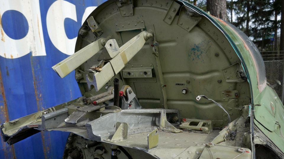
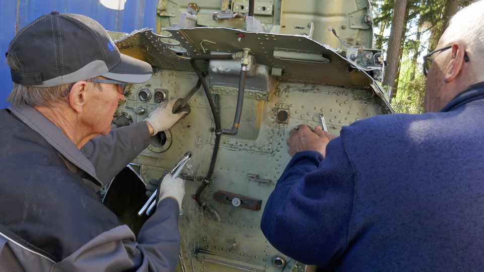
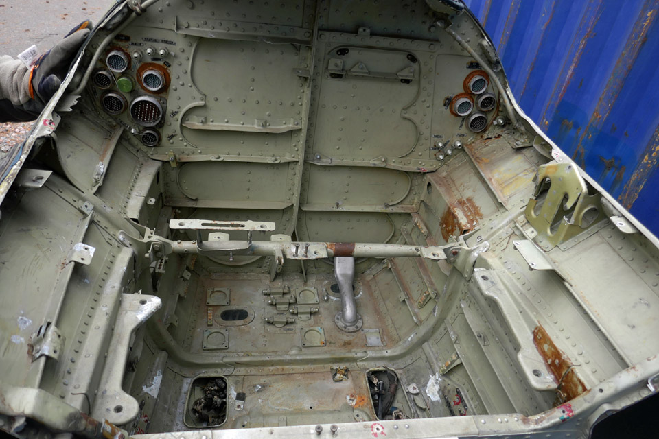
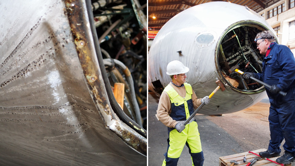
Modifying the cockpit into a simulator means that the equipment and wires outside the cockpit and also partly inside it will have to be dismantled. The dismantling is necessary because space is needed for the simulator hardware and for its assembly.
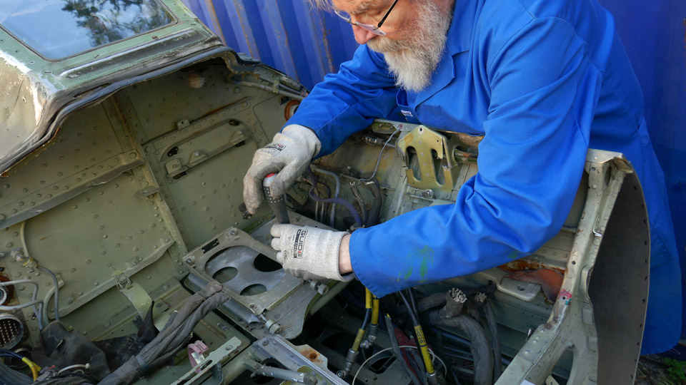
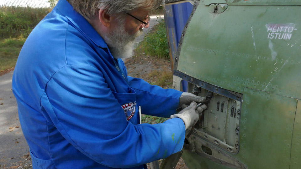
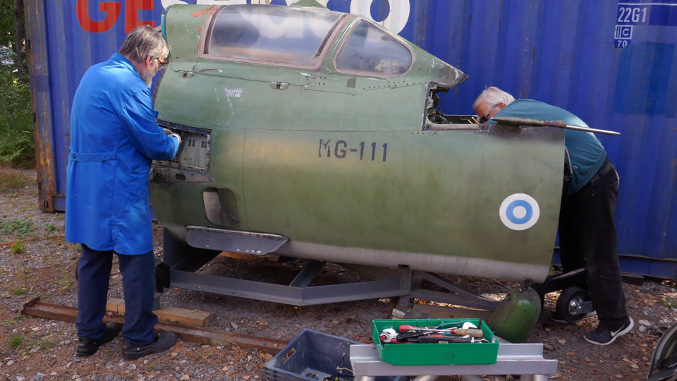
The task for the Tuesday Club was to dismantle wires and equipment in the fuselage, in front of the cockpit and behind it. The dismantling began on May 24th. The work progressed well but it had to be interrupted for the summer break. The dismantling was continued on August 30th when Tuesday Club started its autumn season.
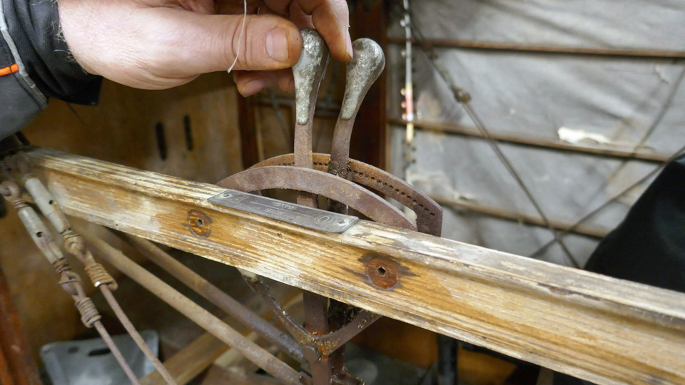
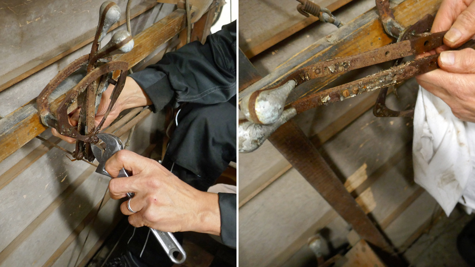
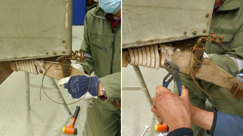
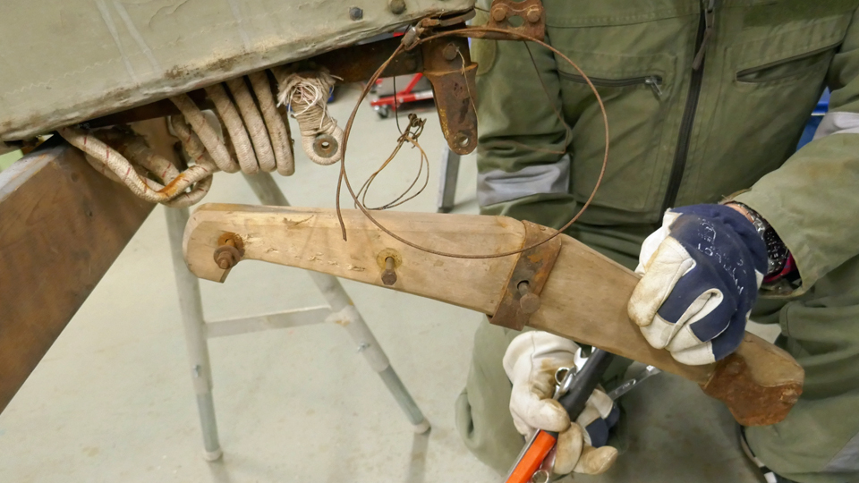
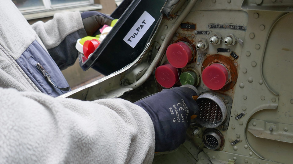
Emptying the equipment compartment in front of the cockpit of all the clobber was a time-consuming job. In a way this was easy too, because the order had been to disassemble and dismantle everything in the best possible way, without a second thought. This is why cutters, and even a hacksaw were used, in addition to the various kinds of screwdrivers and wrenches.
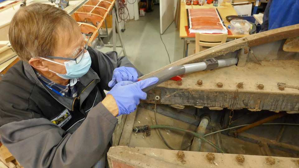
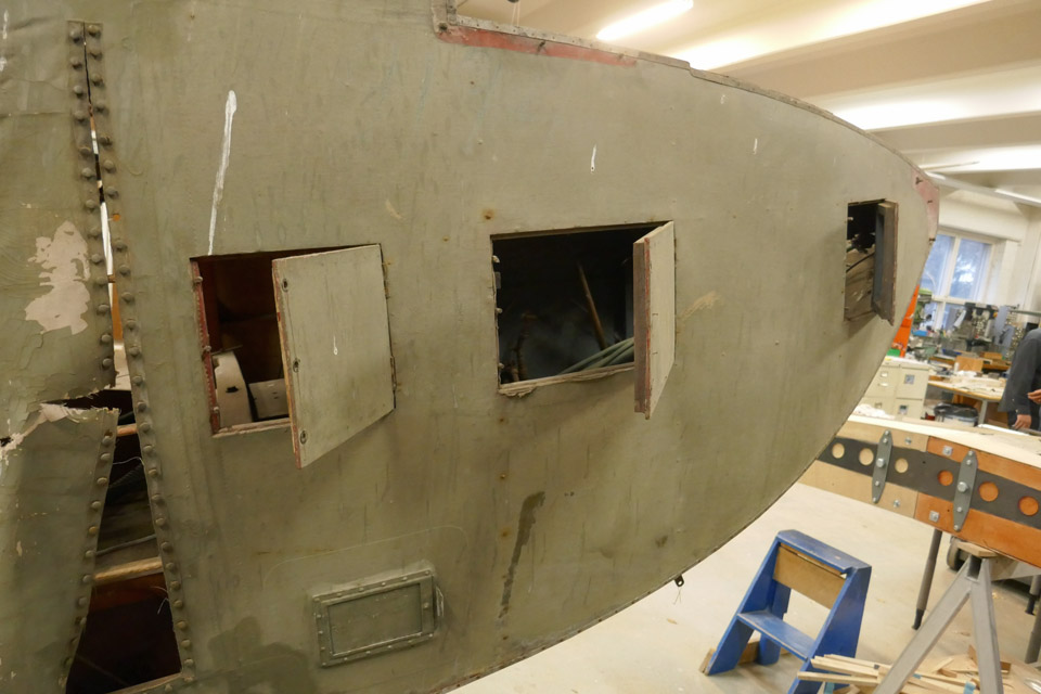
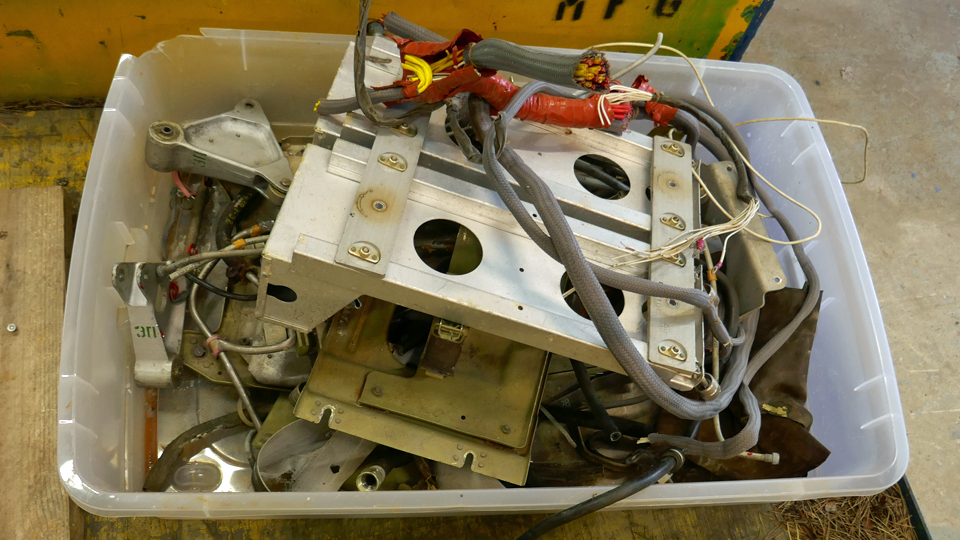
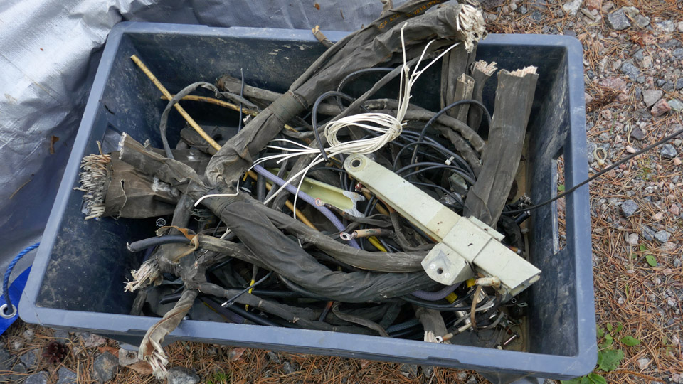
Some work was also needed when the various parts and wires were unfastened from the wall behind the cockpit and from the compartments behind the panels on the sides of the fuselage. Soon there were several boxes filled with disassembled clobber. The cut edges of the fuselage behind the cockpit were dangerously sharp. The edges were filed smooth to avoid injuries.
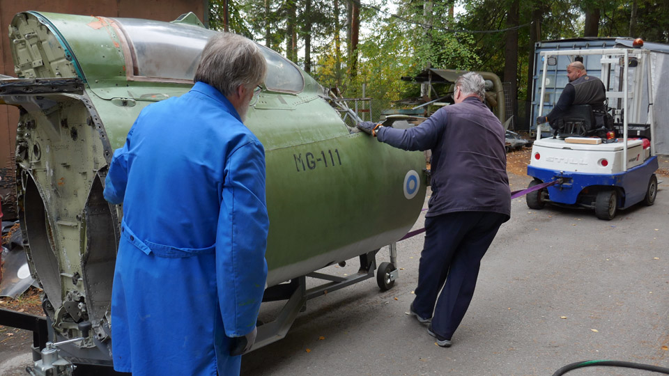
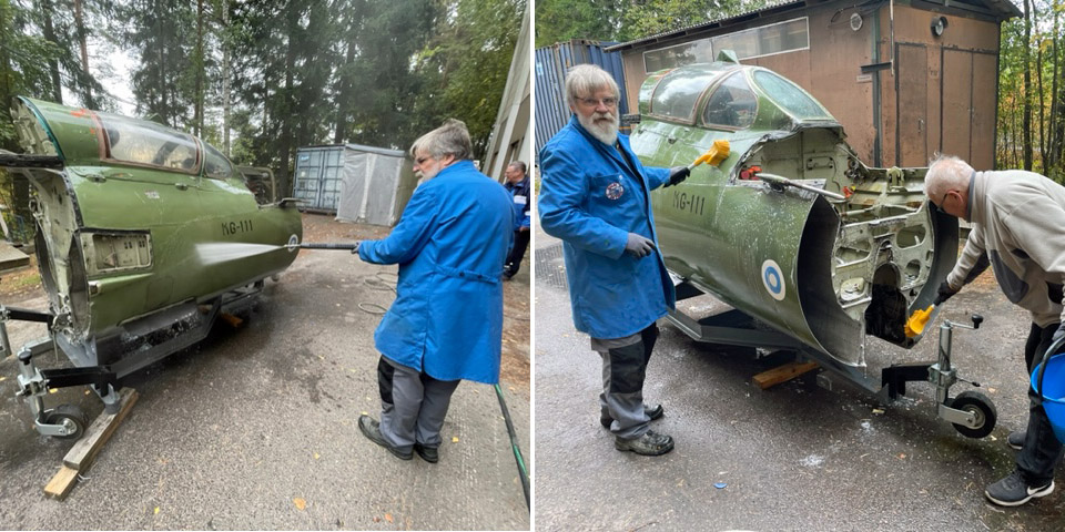
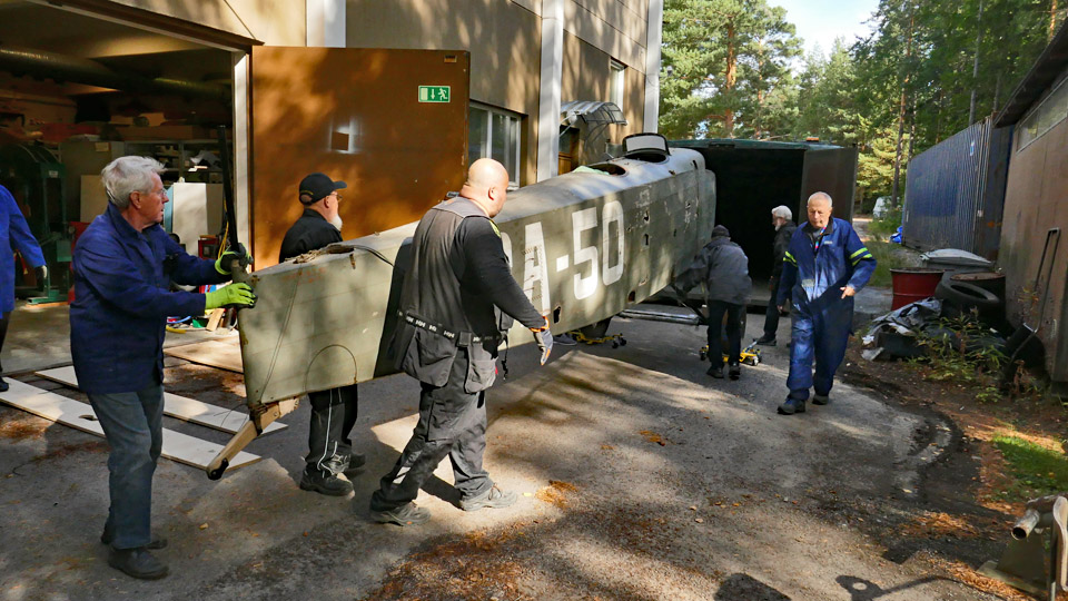
When the equipment and wires outside the cockpit had been disassembled, the cockpit part was towed with a forklift to be washed outside the Finnish Aviation Museum’s restoration workshop. Before using the pressure washer, the feed-through holes to the cockpit were plugged to keep the water outside the cockpit. The wash of the cockpit section was finished using brushes and cloths.
Photos: Antti Laukkanen. Now the cockpit section is waiting to be moved into the Finnish Aviation Museum. There the work will be continued by unfastening the instrument panels and the pilot’s seat, among others. When the simulator equipment is eventually assembled, the unfastened cockpit panels and the pilot’s seat will be returned into their places. Photos: Lassi Karivalo except separately otherwise mentioned. Translation: Erja Reinikainen. |
|
Avainsanat: aviation history, restoration, Tuesday Club, MiG-21BIS, MG-111 |
The Caravelle III towbar restoration beganMaanantai 3.10.2022 - Tuesday Club member In the restoration project of the Caravelle III (ex SE-DAF Sven Viking) owned by the Museum Society, which was brought from Arlanda to Turku, there is a small side line – like the proverbial gnat in the soup – of restoring the Caravelle’s derelict towbar. This tow bar is produced by the SUD AVIATION factory and is of the same production type, although of an earlier version, as the Super Caravelle towbar, used by Finnair, restored by the Tuesday Club into the colours of Finnair during the spring of 2022.
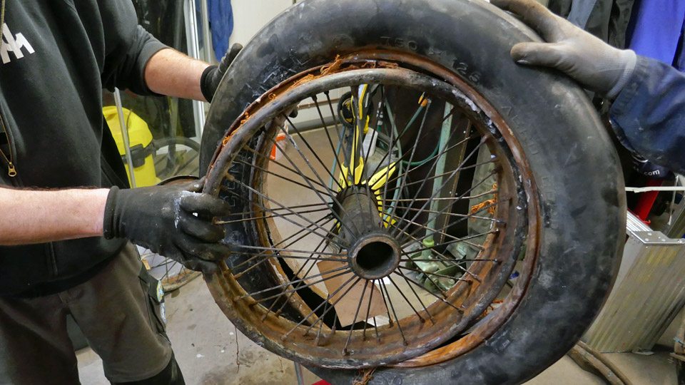
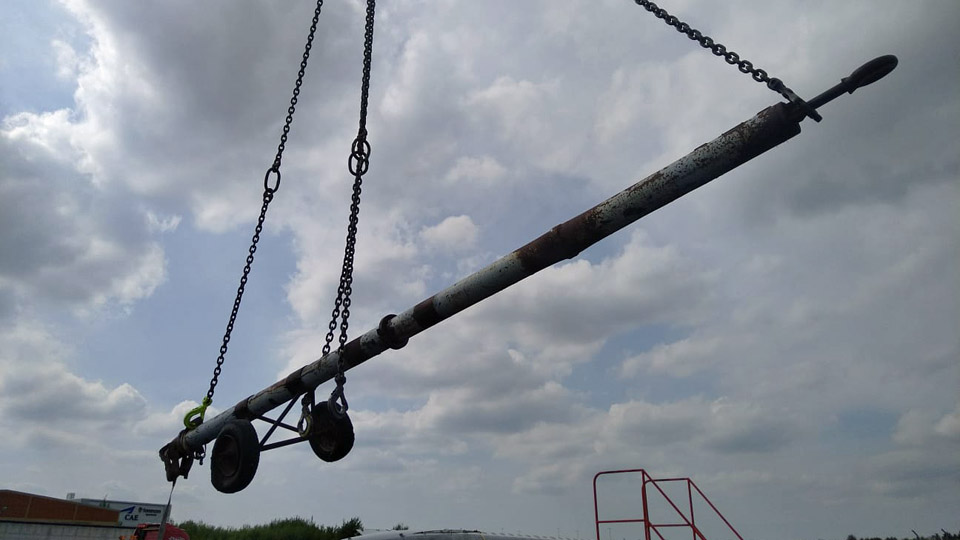
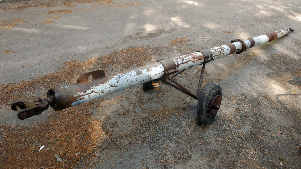
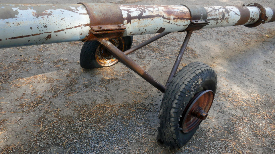
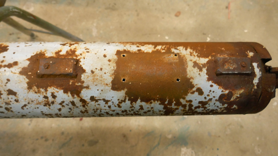
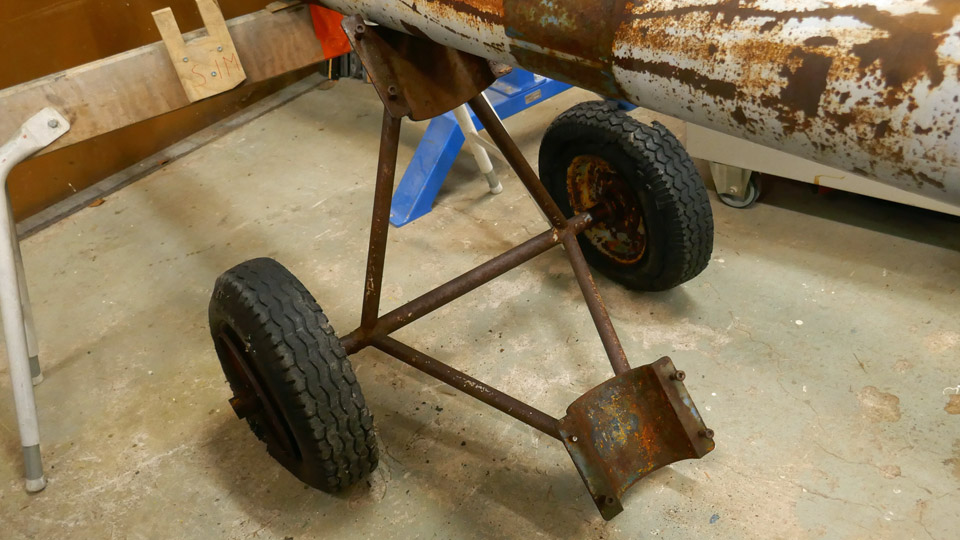
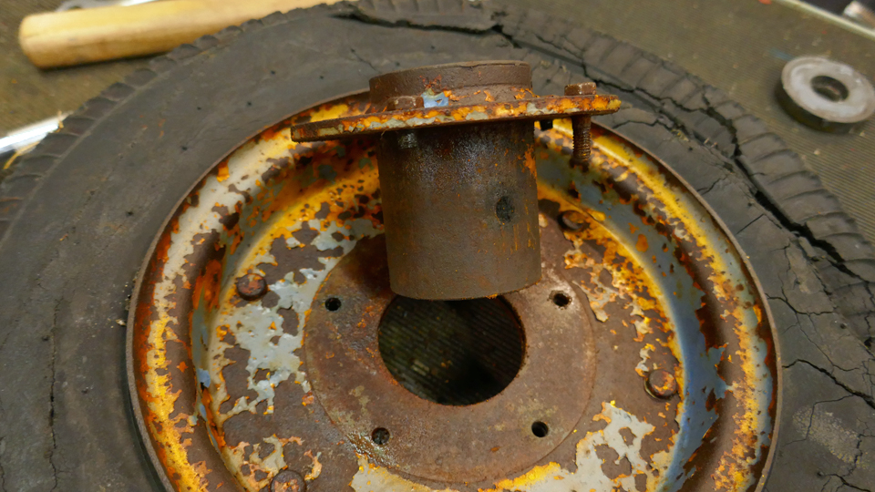
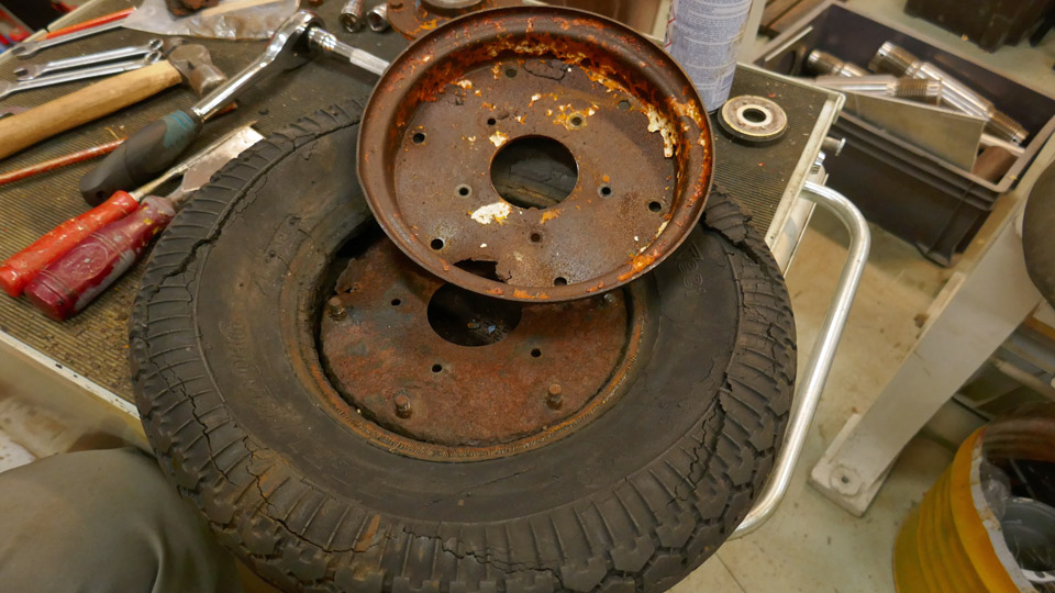
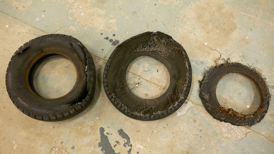
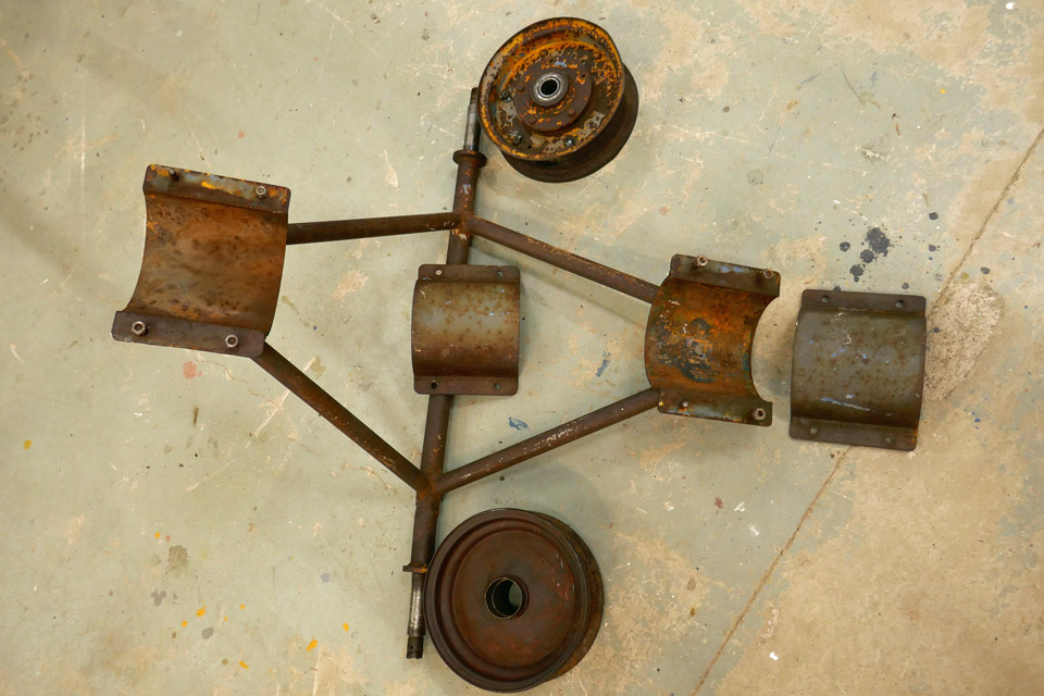
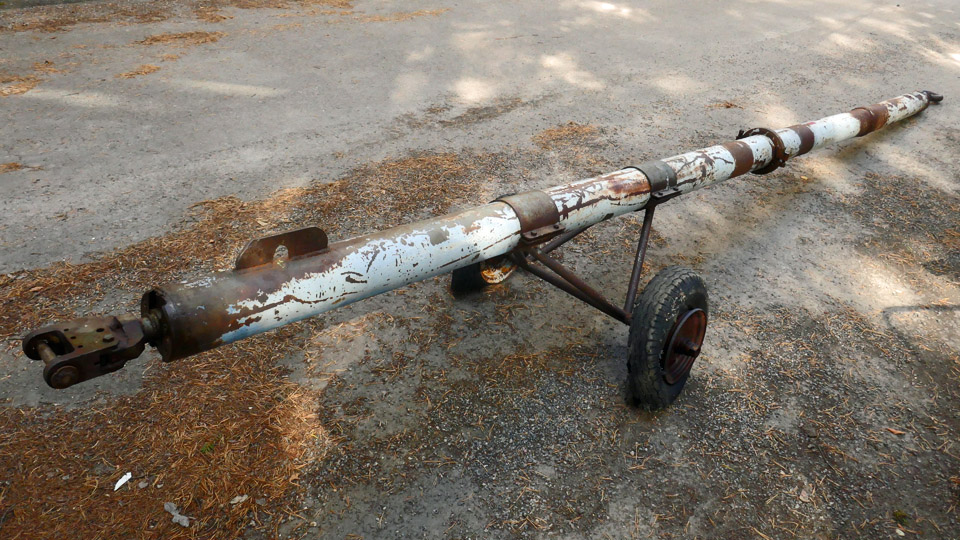
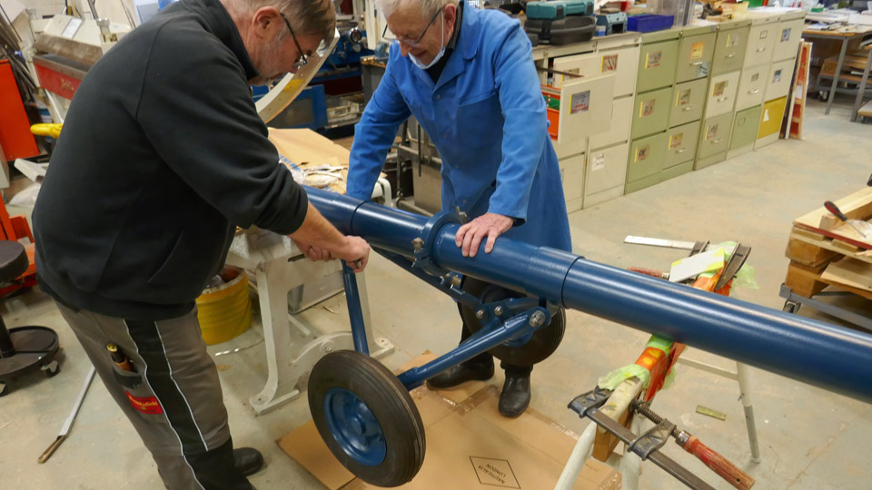
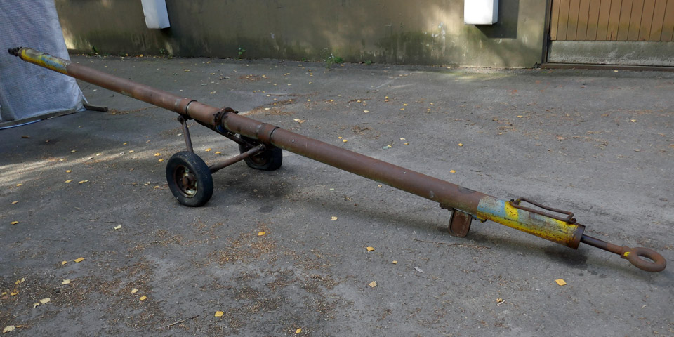
Photo: Pekka Simula. The towbar, brought along with the Caravelle III from Arlanda to Turku, is in much worse condition than the Super Caravelle towbar, which we restored. The rod of the towbar, wheel racks and the wheel rims are covered in thick rust. One of the rims is partly rusted through. The tires are shredded and thus unusable. It is also strange that the rims are quite different from one another. The rim halves of one wheel have been welded to form a solid rim. The halves of the other wheel rims have bolted together. The separate bearing hub is also attached to the rim with bolts.
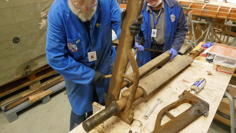
Both ends of the tow bar lack the rectangular handle bars made of metal rods. Only the places of the handle bars with their cut-off fastening screws are visible. A supporting flange has been welded to the rod, which tells us that the rod has been broken at some stage. Perhaps it’s been run over. We really have lots of work cut out for us in the future to restore the rod.
The Caravelle III towbar will not be restored in the SAS livery. It will be made to look like the towbar used by Finnair. Thus the livery of the towbar will be in harmony with the ex-SAS Caravelle III, which will be painted in Finnair colours and is to be put on display near the terminal of Turku Airport. The first Finnair jet airliners were of the Caravelle III type.
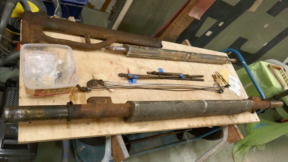
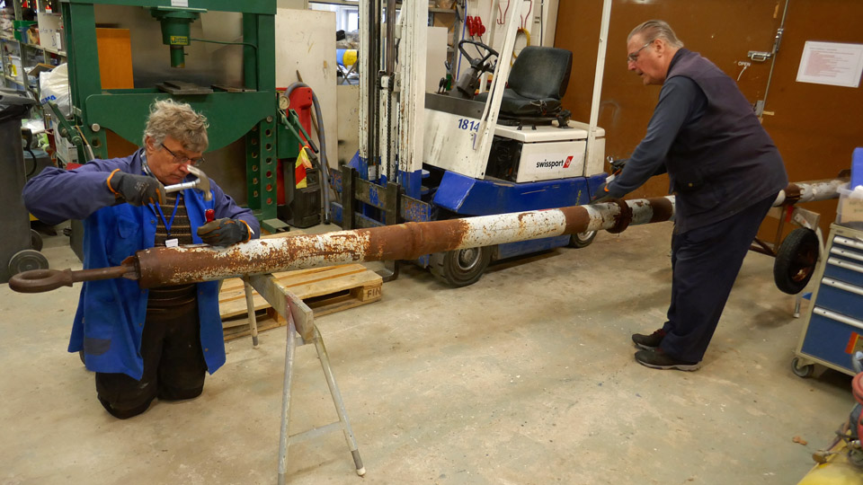
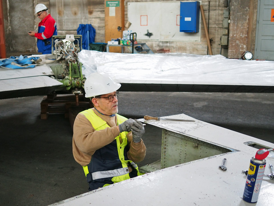
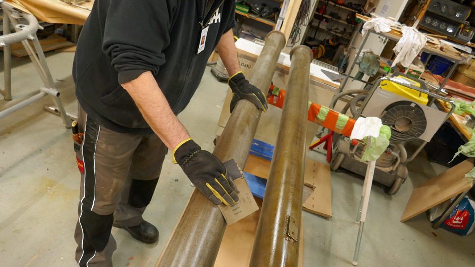
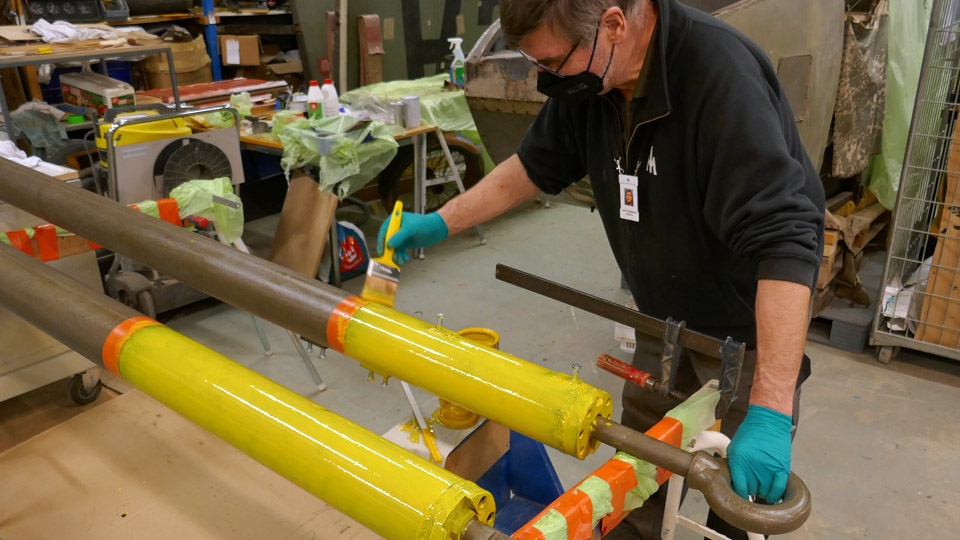
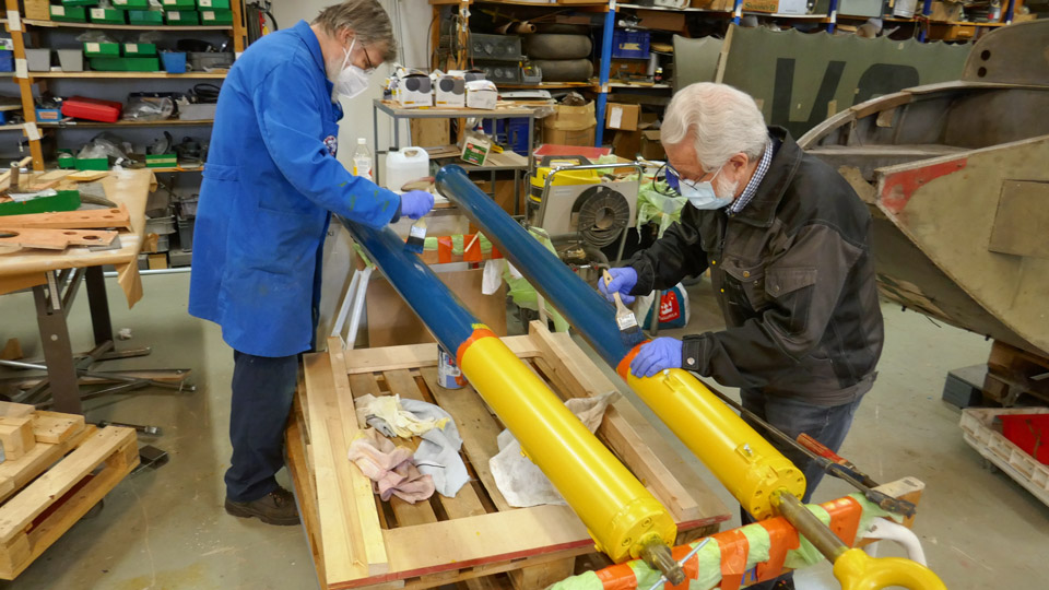
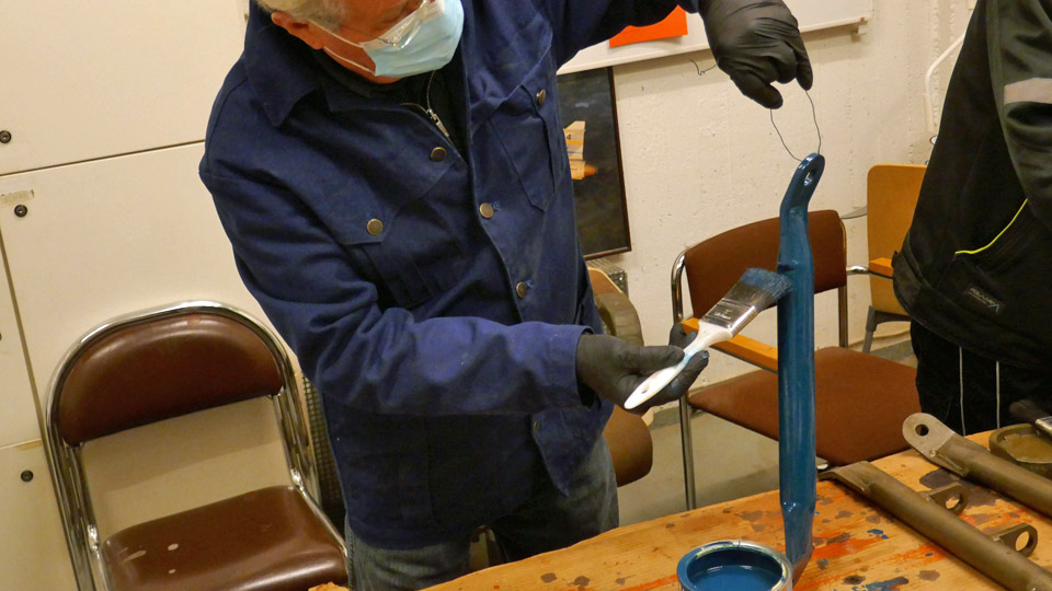
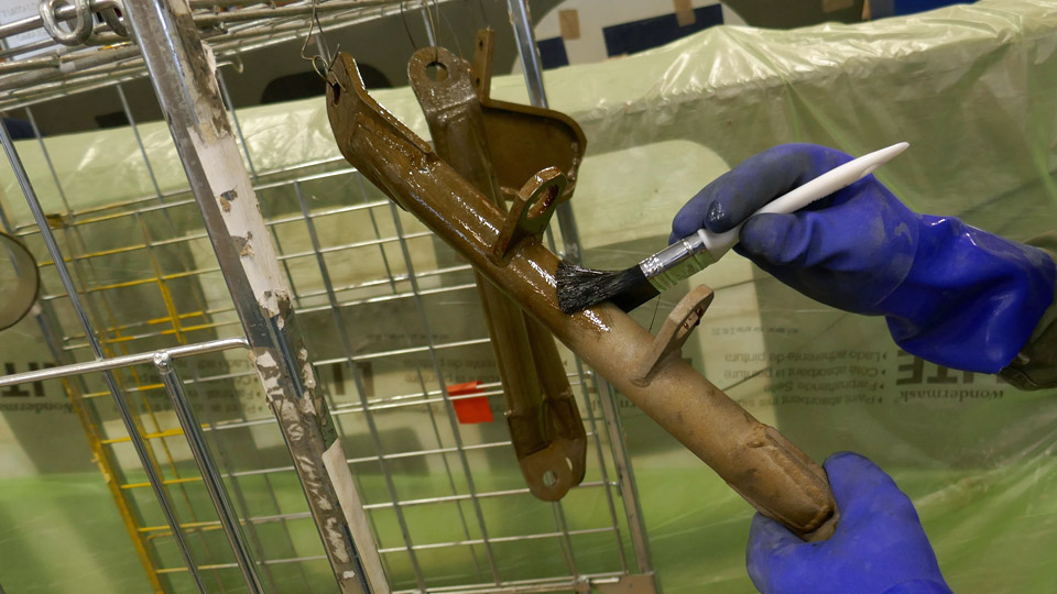
During the restoration the towbar will be dismantled. The rusty parts will be cleaned either by sand blasting or bathing in 30% phosphoric acid. The towbar will be painted “Finnair Blue “, apart from the ends. They’ll be painted with yellow high visibility colour. Before we started to unfasten the parts of the rusty towbar, the rusted bolts and nuts were sprayed with rust dissolving WD or CRC multi-purpose spray several times.
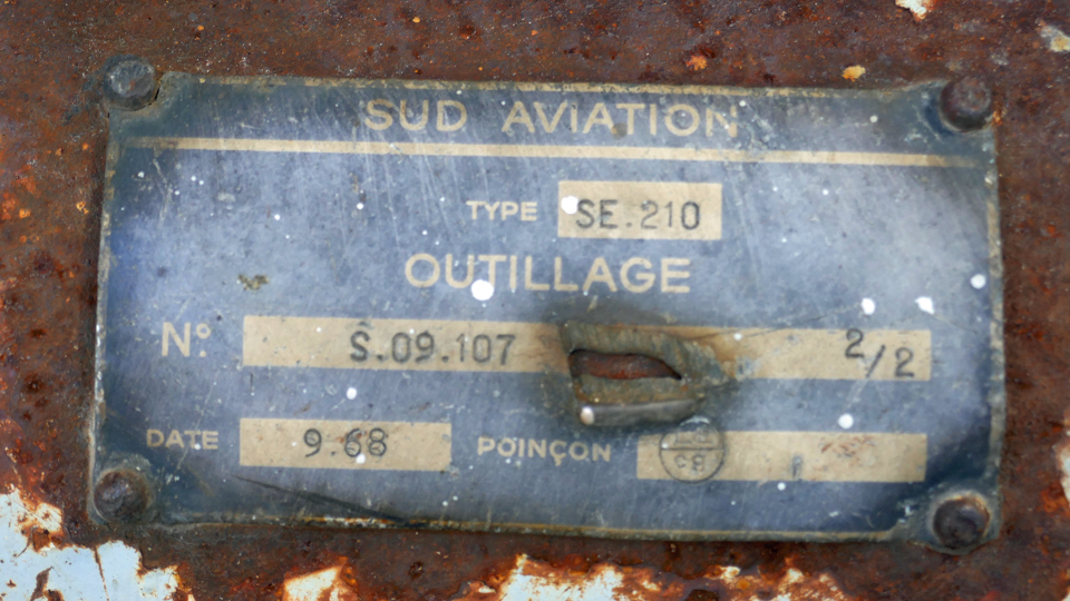
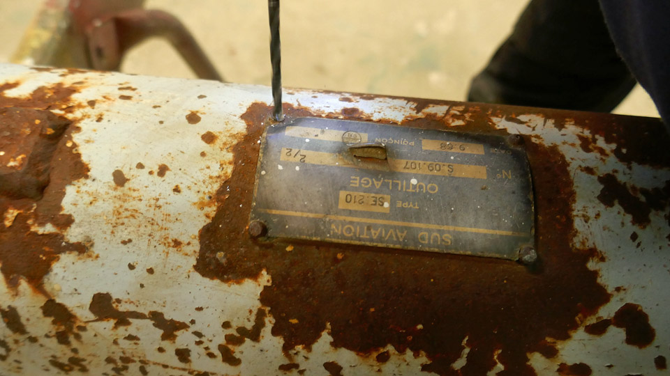
The dismantling began with loosening the manufacturer’s plaque, which was attached to the body of the towbar, in order to prevent it from getting damaged in the sand blasting of the body. To loosen the plaque the rusted and jammed screws in the corners were bored out.
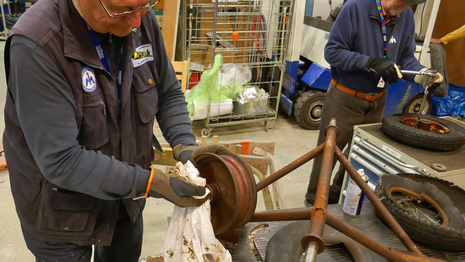
At the same time the dismantling of the towbar’s two wheel racks was started. The nuts of the wheel rack attachment flange bolts were surprisingly easy to open and the rack unfasten from the tow bar. The unfastening of the wheels from the axles followed after this.
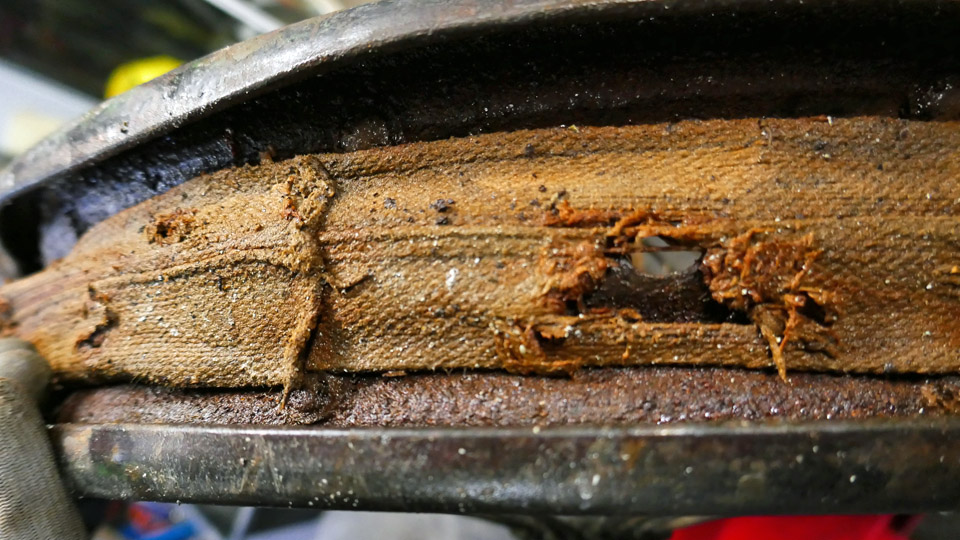
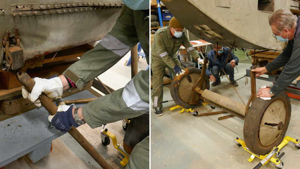
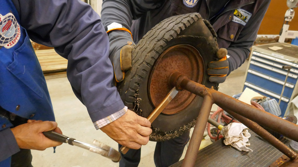
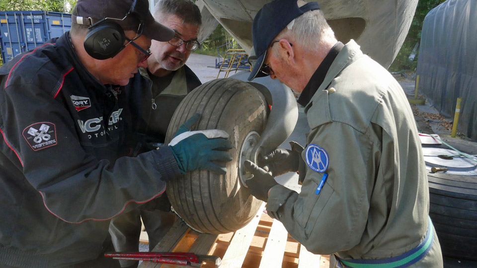
One of the wheels departed fairly easily from its axle. Also the bolts uniting the rim halves could be detached, ditto the bearing hub bolts. However, taking the tyre off the rim proved problematic. The tyre was as if glued to the rim from its one side. In the end the only way was to cut the tyre along the strengthening wire on the side of the tyre with a keyhole saw and yank loose the wire, that was glued to the rim. We found out that the wire in the side of the tyre had simply rusted solid to the rim.
If the problem with one wheel was detaching the tyre from the rim, the other one was difficult to detach from its axle. Finally by using brute force we managed to dislocate the wheel, but at this effort the wheel bearings broke. The tyre was easy to take off from this wheel. The wheel racks with their rims are now ready for rust removal.
Because the rim of one wheel is partly rusted through, and the bearings of the other were destroyed when dislocating the wheel, we have to consider acquiring new wheels for the Caravelle III tow bar. Decision-making time will come, when we see what the rims look like after sandblasting. Photos: Lassi Karivalo except if otherwise mentioned. Translation: Matti Liuskallio. |
|
Avainsanat: aviation history, restoration, Tuesday Club, Caravelle |
Caravelle restoration work has startedLauantai 1.10.2022 - Tero Hyvärinen The restoration work on the Caravelle has started and the volunteers have agreed to work on Tuesdays, Thursdays and Sundays. The aircraft is in the Pansio harbour area, in a large former shipyard hall and there is plenty of space for working. The atmosphere causes a flashback from the 1970s, only the angry foreman and a ruddy shop steward are missing! The hall is about 7 kilometres from Turku centre. The area is guarded and behind a gate, so unauthorized curiosity is prevented, to some extent at least.
At this point different kinds of organizing has been necessary and time consuming. Tools and supplies are gradually being acquired and borrowed. The volunteers have also used their own tools. Tenders for cleaning the outer surface of fuselage have been asked from power washing companies and they have visited the site to estimate the situation.
We are sharing the hall with pigeons, which is somewhat annoying. They seem to have their favourite places among the roof trusses and the equipment underneath must be protected from their droppings. Bird nest housing areas have been found inside the Caravelle’s wings and stabilizers, obviously built during the years at Arlanda.
The existing white layer of paint is very uneven in some areas, and at the moment it also seems that the paint is very hard. There has been some discussion whether the aluminium surfaces will be polished or painted. The amount of work is still difficult to estimate.
Working safety issues are important here, as they are in a paid job. Aviation Museum Society Finland has bought various safety equipment and given instructions on their use. A helmet, safety footwear and protective glasses must be worn in all tasks. When working in high places, harnesses and safety ropes must be used. Those who don’t have a valid working safety card will participate in a working safety course.
Usually there are 5-10 volunteers working on the agreed days. There are former Caravelle mechanics in the team, so up to now real show-stopper problems have not occurred. Ismo Matinlauri is supervising the work and managing the project in Turku. I, Tero Hyvärinen, have promised to take care of photographing and writing blogs. I aim to document the restoration work for future needs and to take also different kinds of snapshots of the working team to be published and for the team’s own purposes. An observation of life philosophy: A get-to-know-each-other game is not the best way to learn to know people, working together is. Photos: Tero Hyvärinen Translation: Erja Reinikainen. |
|
Avainsanat: aviation history, restoration, Caravelle |
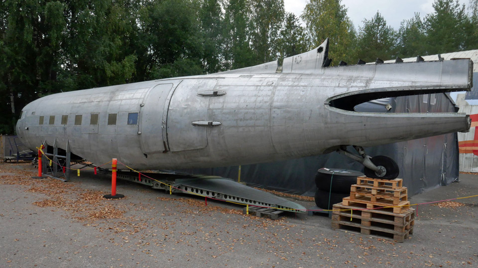
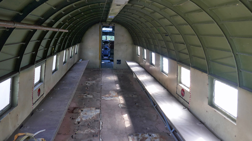
The Tuesday club is starting to restore the DO-5 fuselageSunnuntai 11.9.2022 - Tuesday Club member Aviation Museum Society Finland owns a DC-3 (C-47) DO-5 fuselage with elevators and rudder. The wings are still lacking. The fuselage of the DO-5 came to the possession of the Aviation Museum Society in 2018, otherwise the fuselage would have ended in the scrap yard. The ex- Air Force DO-5 last served as a ground training device with the parachute jumping school at Utti. The DO-5 fuselage owned by Aviation Museum Society has already been used as prop in two movies.
The intention of Aviation Museum Society is to refurbish the DO-5 fuselage so that it could be presented in different outdoor occasions. It would then be possible to get acquainted to the interior of the aircraft. The passenger cabin of the fuselage will be preserved in its existing parachuter training appearance with the canvas benches along the walls. The fuselage will be available to film makers’ needs in the future, too.
The fuselage refurbishment of DO-5 is beginning at the Aviation Museum Society’s Tuesday Club. This is why the fuselage is on the yard of the Finnish Aviation Museum. Well, it will not be ready tomorrow by far, for the club members have their work cut out for them with the refurbishment of the fuselage. But, maybe by the end of spring 2023 the work will be so much advanced, that we could dare to take the fuselage on display at the National Air Show at Turku. Well, time will show.
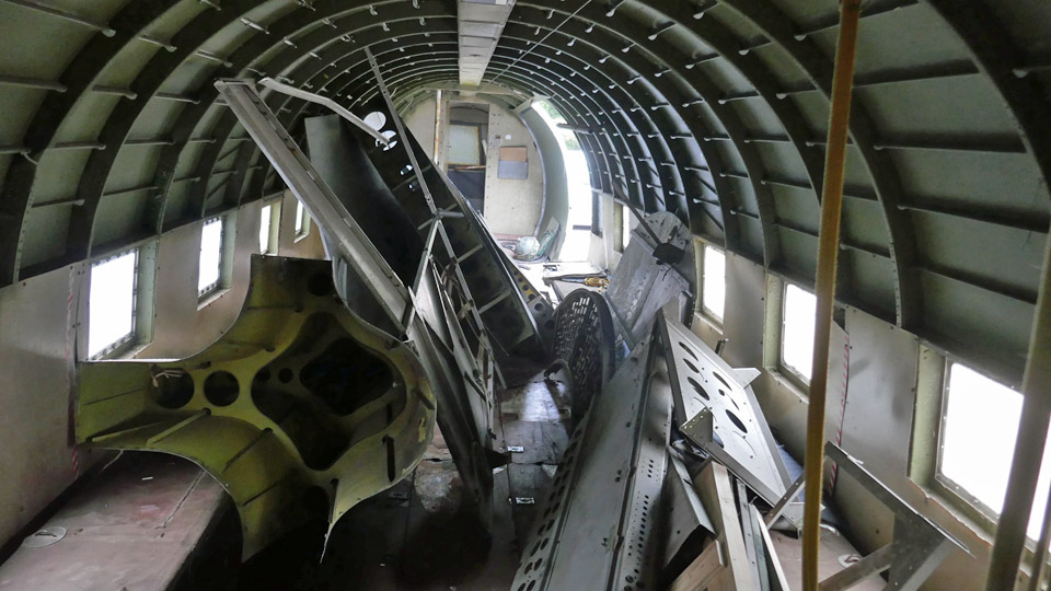
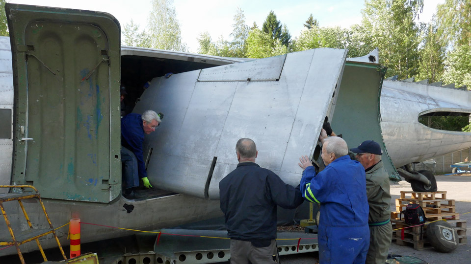
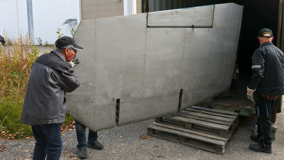
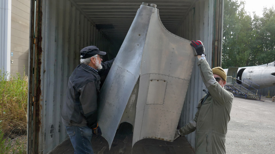
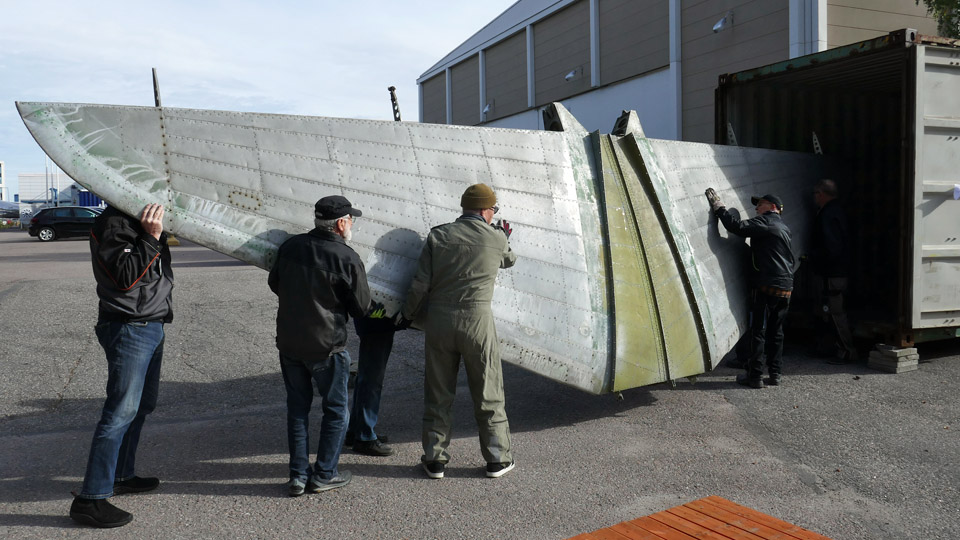
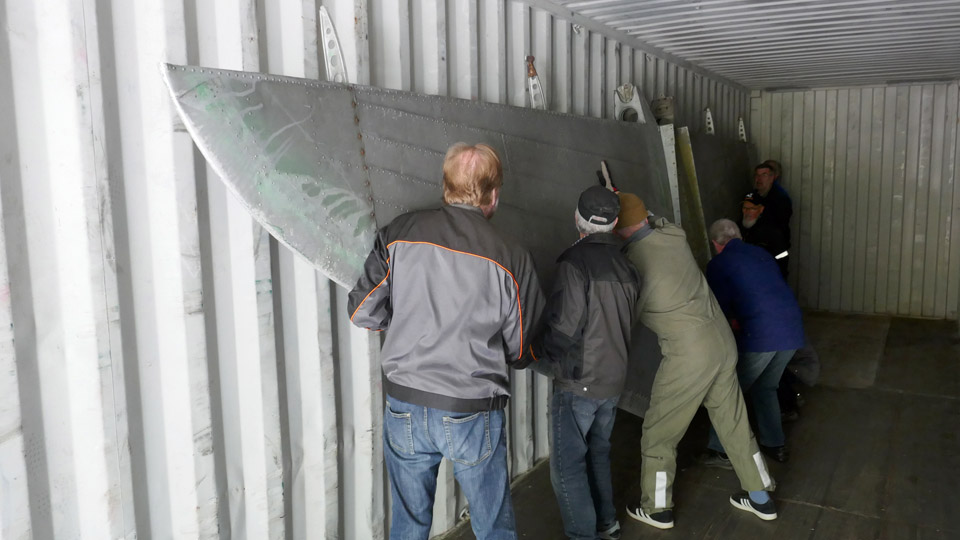
The beginning of the autumn season for the Tuesday Club has been spent on preparations for the DO-5 fuselage refurbishment. One of the tasks will be the removal of the vertical stabilizer, rudder, elevators, the rear cone, nose cone and other parts of the aircraft that were stored in the cabin, to a storage container which was brought to the vicinity of DO-5. The horizontal stabilizer, which was stored under the fuselage, was also moved into the container. The parts that had been in the cabin had to be taken away, because they filled the fuselage so that moving in there was difficult, dangerous even, not to mention working in the cabin during the restoration process.
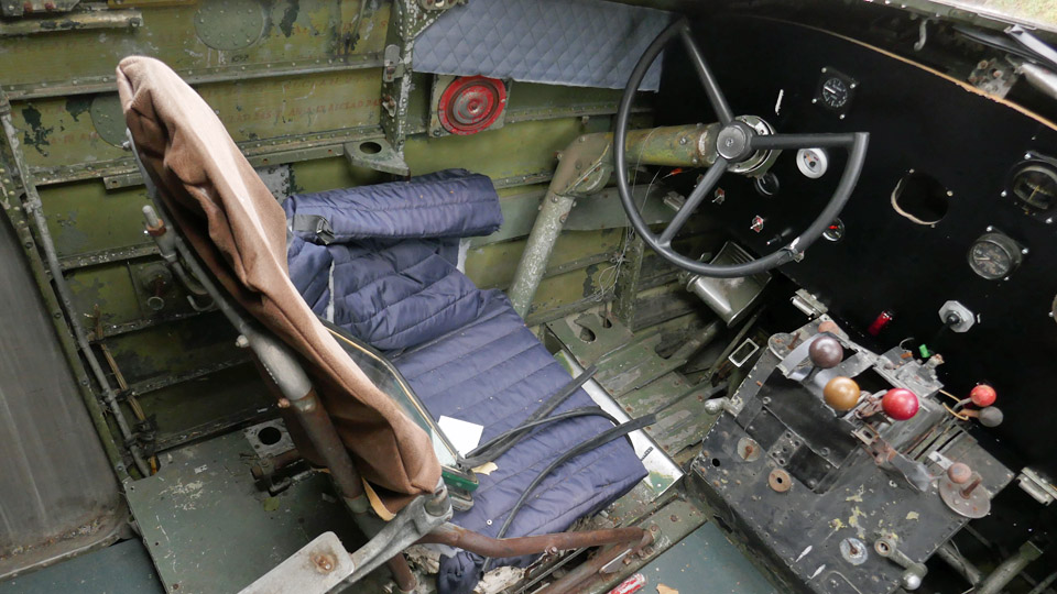
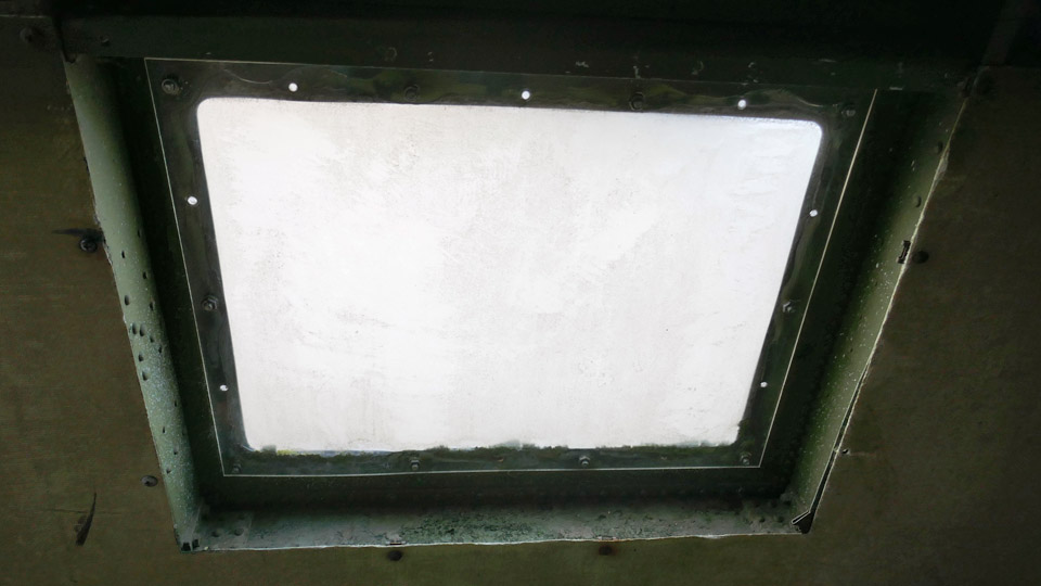
In the restoration of the fuselage, we will concentrate at first on the cockpit. There we’ll have to, amongst other things, to seal the windows and possibly replace them partly with new ones, to detach the pilots’ seats for refurbishment, to clean the cockpit surfaces and remaining equipment and to paint the wall surfaces.
We have already accomplished something in the field of restoring, when the legendary DC-3 mechanic Pauli “ Speedy” Fallström replaced the broken tail wheel with a new one. Photos: Lassi Karivalo Translation: Matti Liuskallio |
|
Avainsanat: aviation history, restoration, Tuesday Club, DO-5;DC-3, C-47, Dakota |
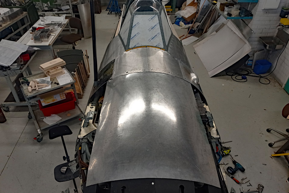
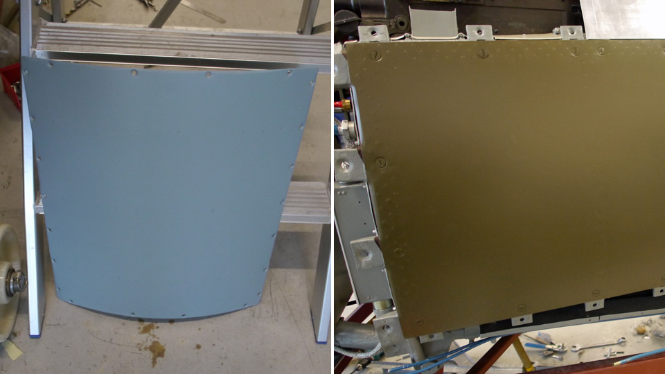
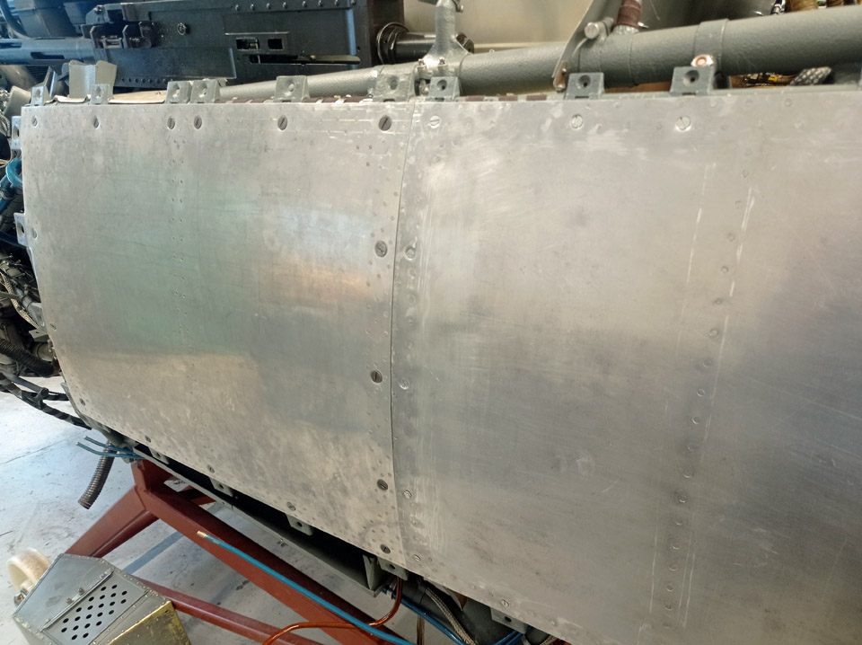
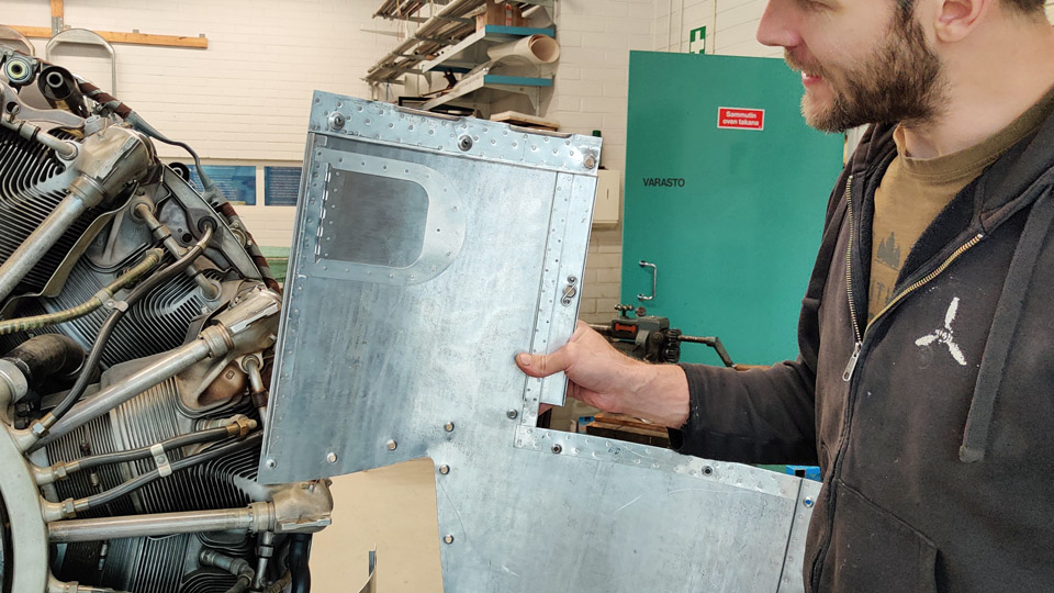
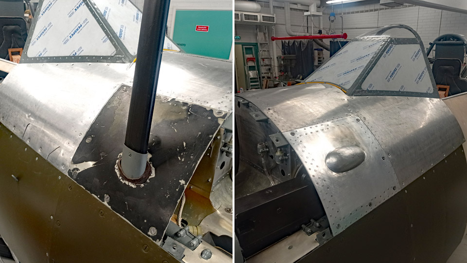
A glance under the cowling at TikkakoskiLauantai 10.9.2022 - Reino Myllymäki The undersigned had a chance – and need, too – to visit Tikkakoski to see how the restoration of MY-14 proceeded there. The work on the aluminium sheets forming the front part of the fuselage of MY-14 to make the opening hatches was nearly finished. Of the original sheets of aluminium there remained only a small piece around the root of the antenna mast. It had been part of MY-5 at its time. MY-5 and MY-6 have proved to differ from the other aircraft of the main production batch, even though they belonged to it.
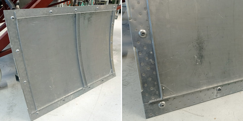
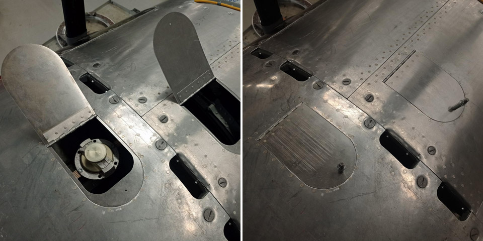
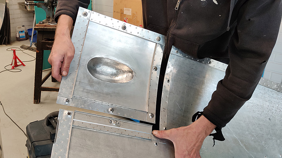
Photos: Finnish Air Force Museum. On the front fuselage sheets there are hatches for entry to the filler caps of the oil-and fuel tanks. There are similar hatches elsewhere, too, but for some reason the width of the hatch for the fuel tank is 10 cm, whereas the width of all other hatches is 11 cm. Because of the 1 cm difference, the parts of the hatch differ from all other hatches. The reason isn’t known, one only wonders….
By turning the sheets, more peculiarities appear. The hatches have “happened to be” in a strange position, so that the sheet stiffeners had to be modified so that the side reinforcements, that form the lips of the hatches, could be fitted.
The jigsaw puzzle consisting of pieces of sheet metal is impressive, and the sheets could not have been cut according to plans, but the cutting lines had to be improvised. Such is the situation in restoration, but the state of the affairs has probably been the same when the aircraft were constructed at their time. Some of the braces attach straight to a counter piece in the fuselage, which means that a piece has been cut off from the sheet below. In another place the brace is attached straight to the sheet of aluminium beneath. After a couple of hour’s wondering, the MY-14 stabilizers were packed in my car, where their journey continued to Vantaa. Photos by Reino Myllymäki, unless otherwise indicated. Translation by Matti Liuskallio. |
|
Avainsanat: aviation history, restoration, MY-14, VL Myrsky |
The autumn season for the Tuesday Club kicked offSunnuntai 4.9.2022 - Tuesday Club member The Tuesday club summer break ended on August 30th,2022, when club members gathered at the Finnish Aviation Museum to continue the projects left from the spring and begin a few new ones. The restoration of VL Myrsky II (MY-14) went on through the summer apart from a few weeks’ break.
The Caudron C.59 conservation goes forward amongst other things with getting the fabric covering of the lower wings ready and repairing the leading edge damage, covering the bare horizontal stabilizer and one of the elevators, and the refurbishment the 1920s aircraft wheels, which were obtained from the Air Force Museum. The Caudron’s fuselage, which had been under refurbishment at the Tuesday Club was returned to the Päijänne-Tavastia Aviation Museum at Vesivehmaa on August 30th to wait for a time when the conservation of the badly crackled paintwork of the fuselage can be fully attended to.
When the MiG-21BIS (MG-111) was dismantled on the yard of the Finnish Aviation Museum to be scrapped, Aviation Museum Society salvaged the cut-off cockpit part of the fuselage to be built as a MiG-21 simulator. The task of the Tuesday Club is to dismantle the gadgets and equipment outside the cockpit to make space for the simulator hardware. We started this work already at the end of the spring, and now we will continue to prepare the part of the fuselage with the MG-111 cockpit to be made into a simulator.
In 2018 Aviation Museum Society salvaged from being scrapped the fuselage of DO-5, an ex- Air Force DC-3 (C-47). The fuselage had last served with the parachute training school at Utti as a ground instruction device. The work of the Tuesday Club is to repair and tidy the cockpit, which is rather dilapidated and lacking equipment, seal the cockpit windows and renew the cabin widows, now opaque.
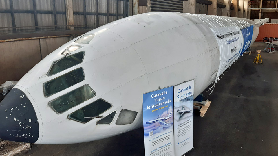
The Caravelle III (SE-DAF), acquired by Aviation Museum Society from Sweden, arrived on Friday August 19th from Arlanda to Turku and was taken to be refurbished into a harbour hangar in Pansio. At its time, the aircraft will be on display in Finnair colours by the terminal building at Turku Airport. Finnair used Caravelle III aircraft before changing into Super Caravelles.
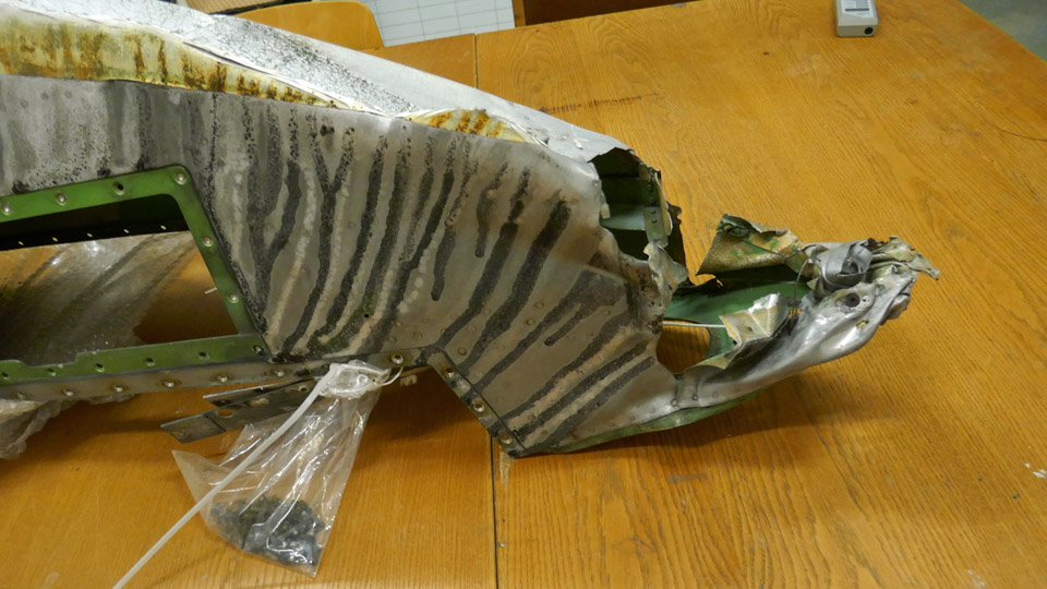
The aircraft had stood by the side of Arlanda Airport since 1974 and was in a bad shape, as could be expected. The task for the Tuesday Club is to repair those damaged parts that for their size are suitable to be repaired in the repair shop of the Finnish Aviation Museum. These include, amongst other things, the somewhat damaged leading edge of the right wingtip. We also restored the Caravelle III tow bar, brought to Turku with the Caravelle, which was in a poor condition.
As usual, many other tasks will appear during the autumn season for the Tuesday Club to do, for the benefit of the Aviation Museum as well as the Aviation Museum Society. Photos: Lassi Karivalo Translation: Matti Liuskallio. |
|
Avainsanat: aviation history, restoration, Tuesday Club |
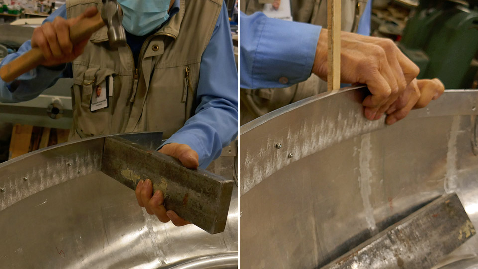
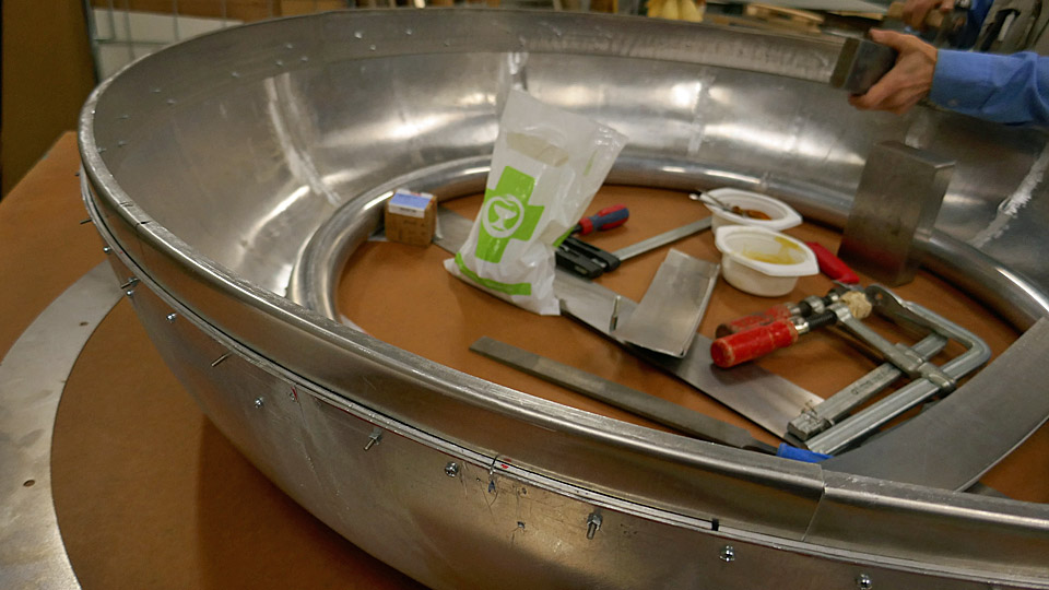
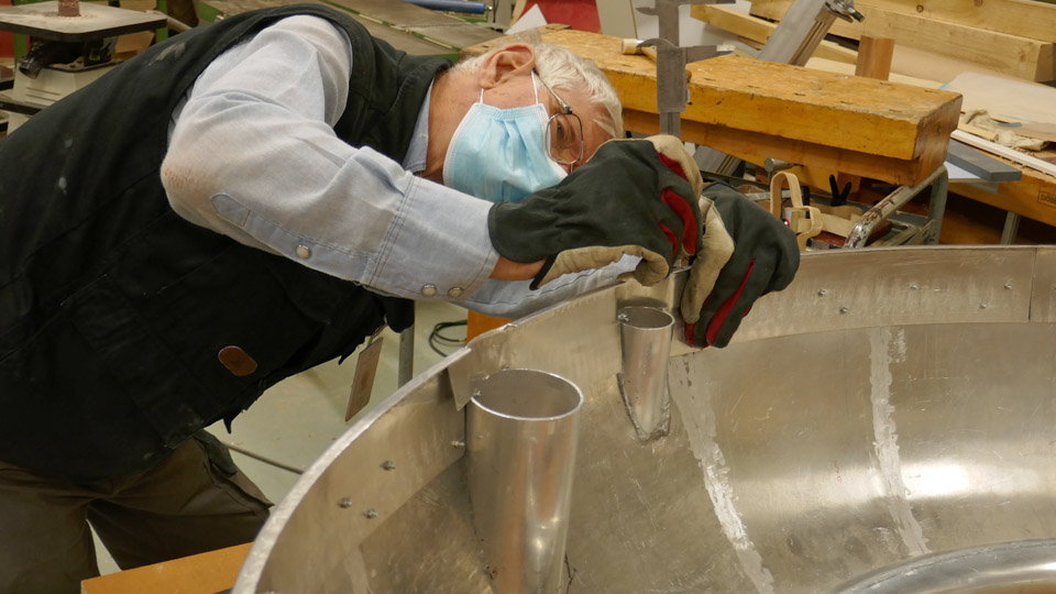
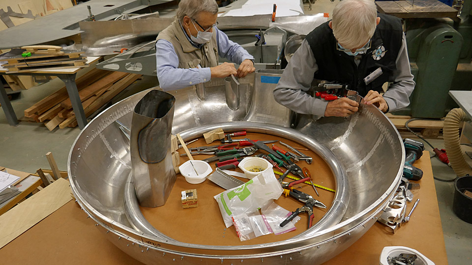
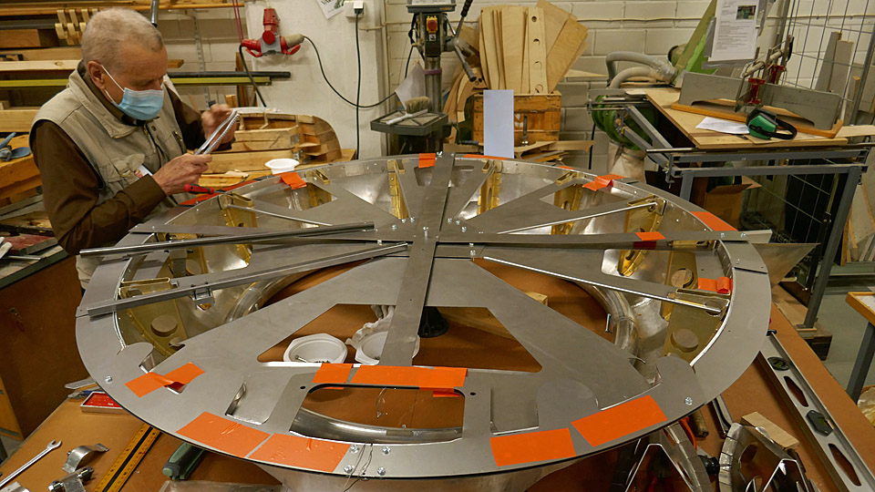
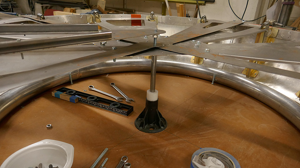
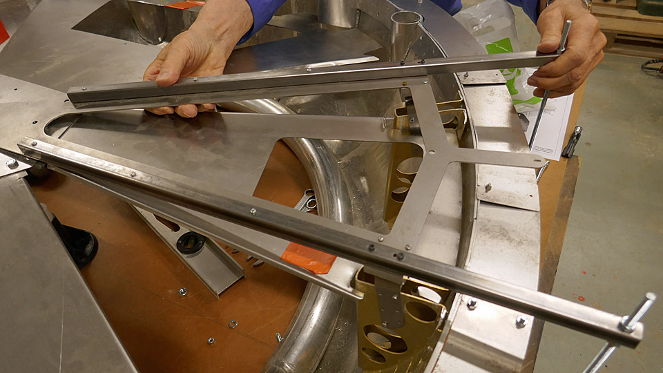
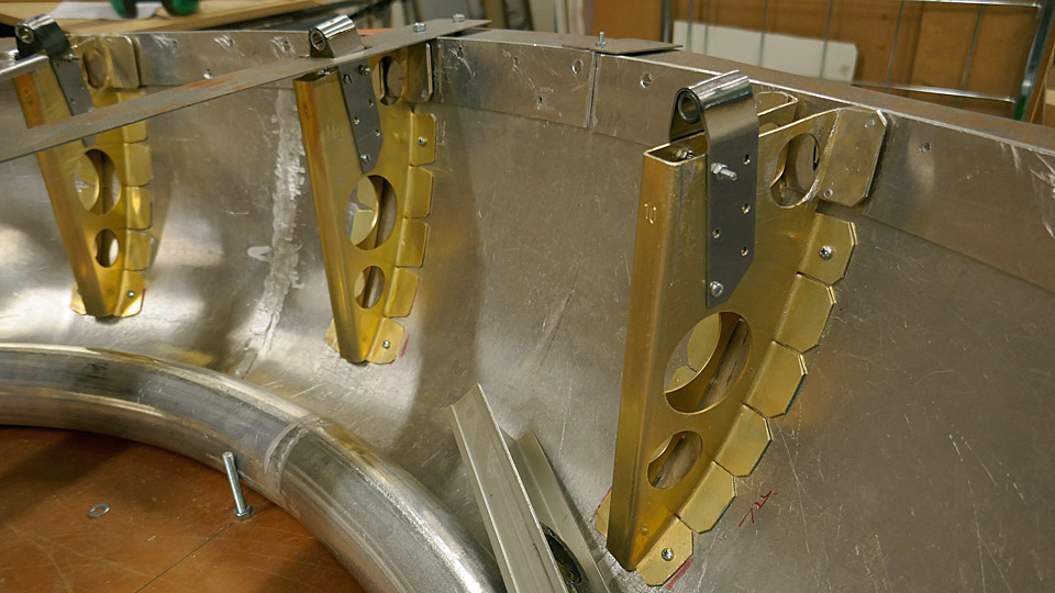
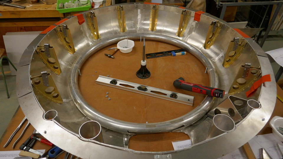
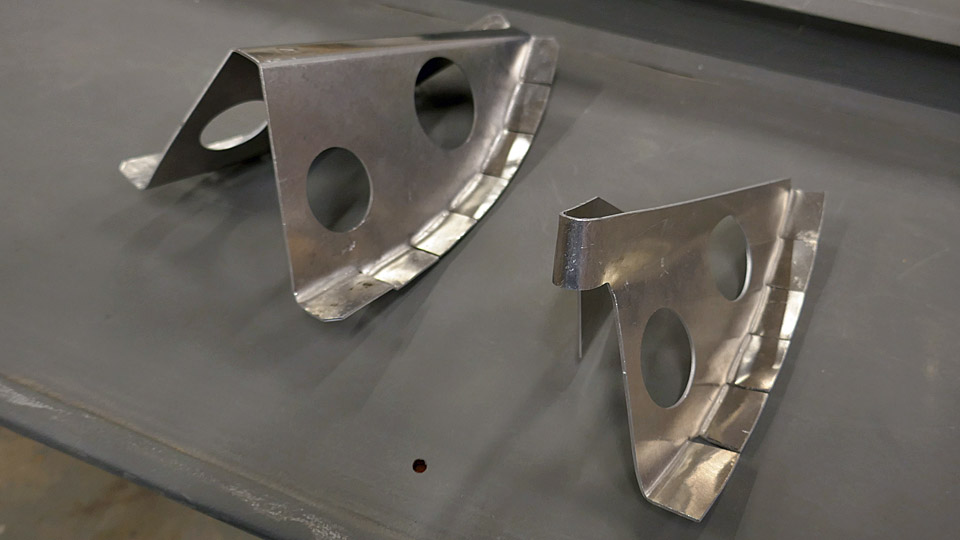
The fitting of Myrsky's NACA-ring bracket formers and brackets for rivetingTiistai 19.7.2022 - Tuesday Club member In the restoration of VL Myrsky II the construction of the engine cowling or NACA ring front part, which is demanding, has been under work already for a couple of years. The Myrsky engine cowling consists of the engine covering NACA ring’s solid front and rear parts and the openable engine cowlings between them. This blog deals with the installing of the bracket formers to be riveted to the solid front part of the NACA ring. Later in this blog the solid front part of the NACA ring will be called NACA ring for simplicity. The Myrsky’s NACA ring has proved to be very difficult to make, and we have not managed to avoid extra work. This was caused by amongst other things the uncovering of the lost Myrsky major series NACA ring drawings at the end of last year. They differ especially in the upper part from the initial series Myrsky’s NACA ring drawings, according to which we have been building the MY-14 NACA ring. The difference between the drawings was, that in the major series NACA ring the diameter of the upper part of the ring is larger than that of the initial series. Because of this, the NACA ring that we had built had to have its upper part diameter increased, so that it would correspond to the shape of the major series shape of MY-14. The enlargement was possible by forging the upper part of the aluminium ring to the measurements of the major series. There are 14 bracket formers in the NACA ring altogether. Of those, ten are situated in the part of the NACA ring, which equates the rotation block. Four bracket formers are situated aside from the rotation block in the expanding upper part of the NACA ring. The opening of the air horn and the flame tubes of the four machine guns are situated in this area.
At the same time a jig was made out of a steel plate, to assist in focusing the bracket formers to their places. With the aid of a set up jig, which was made out of steel plates and locked in the “central hub” of the assembly table, two bracket formers can be positioned into place. After that the jig is moved forward to position and install the next bracket formers. The positioned bracket formers were fastened to the NACA ring with a couple of small bolts. The final fastening will be done by riveting.
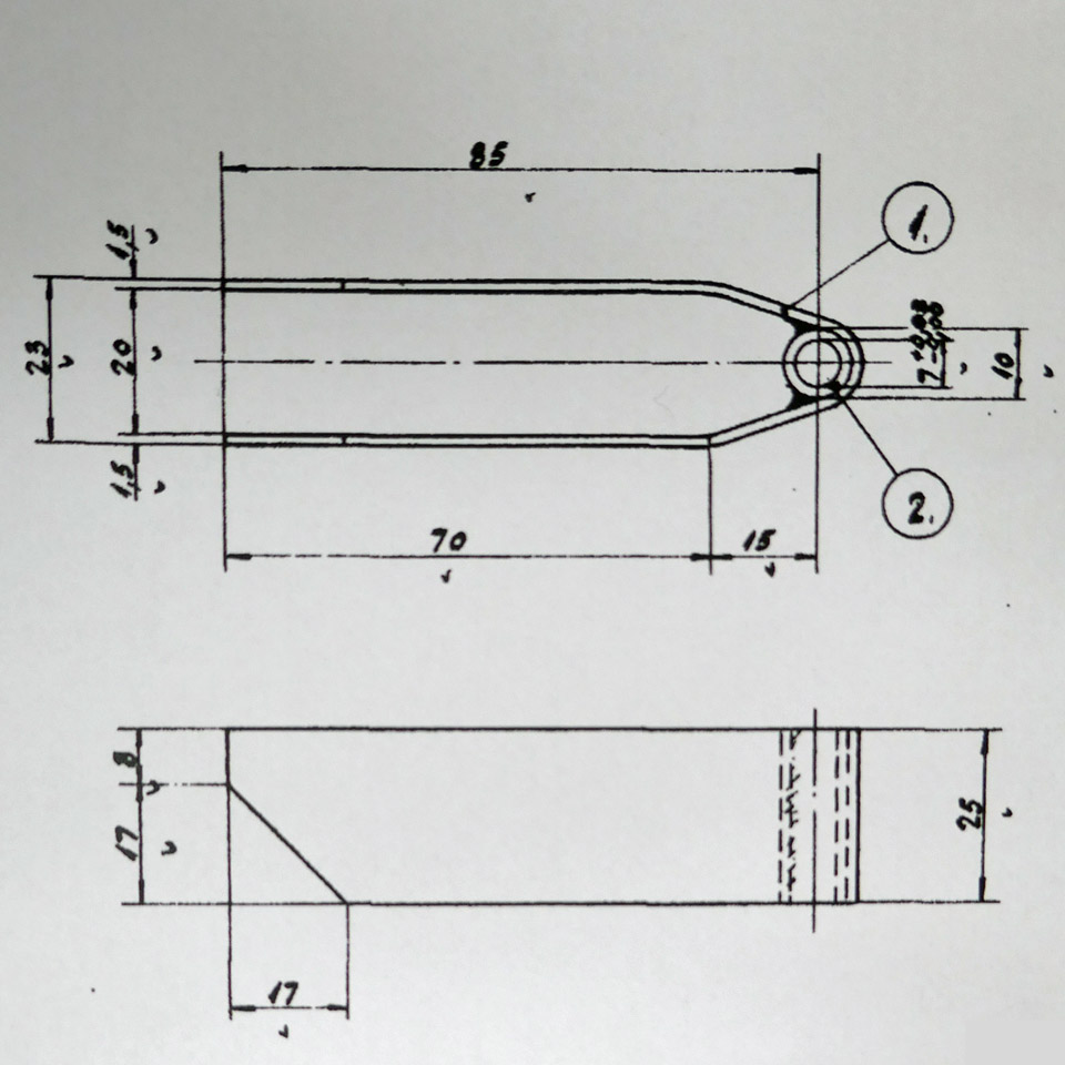
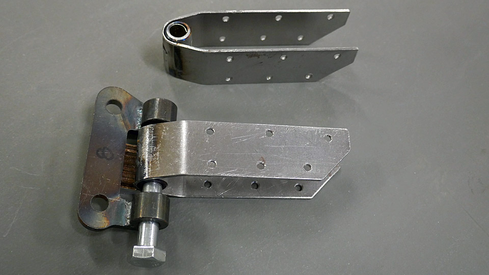
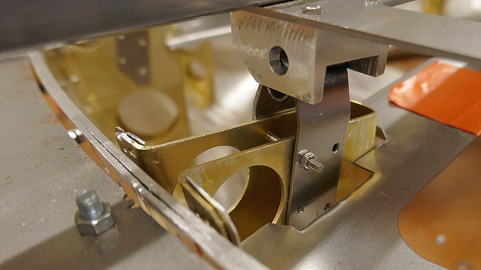
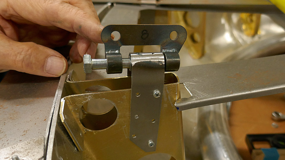
When the chromated 10 bracket formers had been installed, the actual brackets were installed at their tips, with which the NACA ring is locked with connection pieces to the eyes of the valve housing of the engine. The bracket on the former is a prong-like piece, bent from 1 mm steel plate, which has a welded socket for the fastening bolt at the end.
The brackets are installed at the end of the formers at an angle of 7.5 degrees. So they will meet the valve housing eyes to fasten the NACA ring to the engine. The brackets of the formers and the eyes of the valve housing are locked to each other with connecting pieces. The connecting pieces are fastened with bolts to sockets at the end of the former and with two bolts to the holes of the eyes in the valve housing.
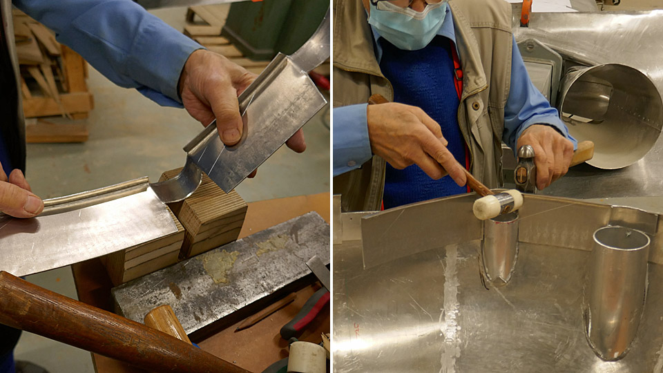
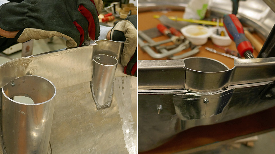
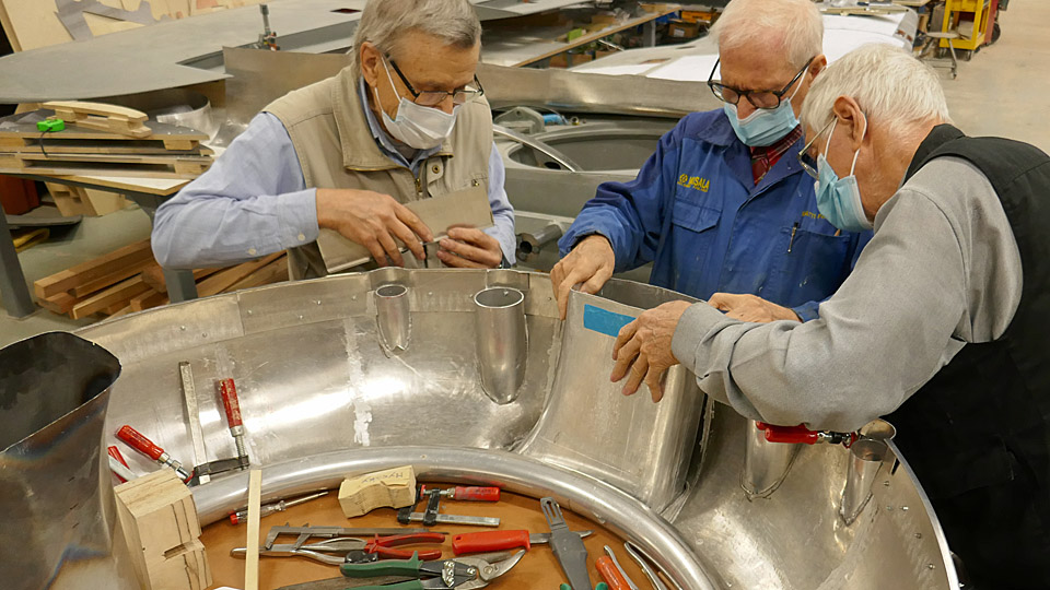
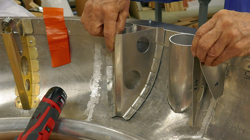
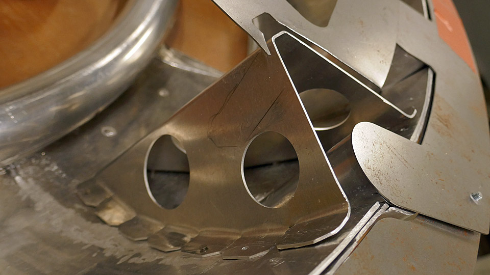
When all ten chromated bracket formers with their brackets had been installed in place, the shaping work of the four bracket formers and their brackets to be installed on the upper part of the NACA ring was started. The bracket formers by the outer flame tubes are distinctly shaped more open-angled, compared with the other V-shaped bracket formers, to enable the flame tubes inside them. The bracket formers that are fixed on either side of the air horn differ from the other bracket formers in shape. In a way they are only half-sized compared with the other V-shaped formers.
First the open-angled bracket formers at the flame tubes were shaped to be installed. They were fastened tentatively in place with the aid of a jig, made especially for these two brackets. After this the shaping of the prongs, attached at the end of the bracket formers with sockets, so that they could be shaped into the form of more open bracket formers. The position of these brackets differs from the other bracket formers so that the bracket is right at the top of the bracket former. The installing of the bracket formers of the NACA ring upper part are still under work. Photos: Lassi Karivalo Translation: Matti Liuskallio. |
|
Avainsanat: aviation history, restoration, Tuesday Club, MY-14, VL Myrsky |
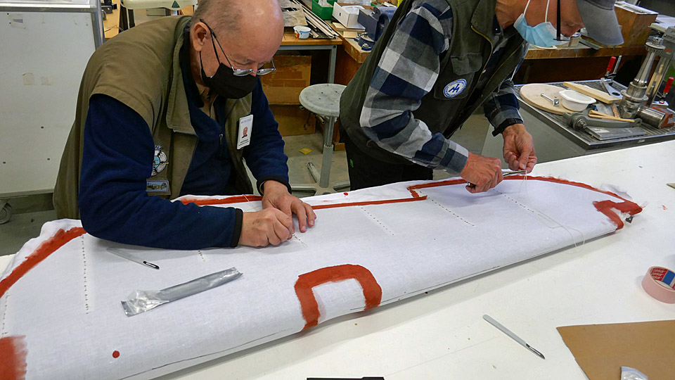
The Myrsky elevators? primingKeskiviikko 6.7.2022 - Tuesday Club member The VL Myrsky II (MY-14) elevators’ coating, which had started in April was finished at the beginning of May. As coating fabric, a 165 g/m2 linen fabric was used.
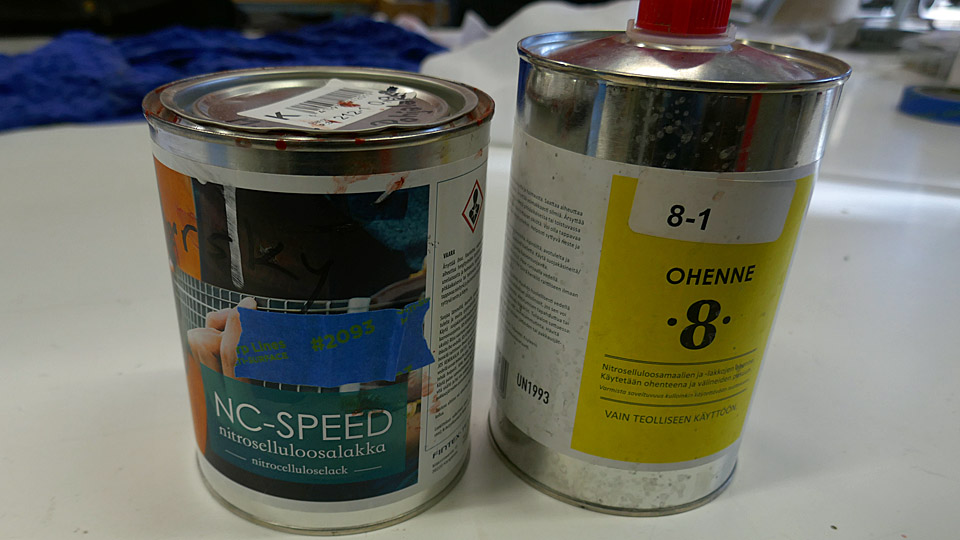
After the elevators were finished, the fabric was tightened to resemble a drum top with NC-SPEED nitro cellulose varnish. The varnish was dyed red with iron oxide. The tightening of the fabric was done phase by phase. It began with 50% thinned varnish. Thinner 8 was used for the purpose. From that we continued through 75% varnish to a full 100% varnish. Unthinned varnish was applied twice to the fabric cover of the elevators.After the elevators were finished, the fabric was tightened to resemble a drum top with NC-SPEED nitro cellulose varnish. The varnish was dyed red with iron oxide. The tightening of the fabric was done phase by phase. It began with 50% thinned varnish. Thinner 8 was used for the purpose. From that we continued through 75% varnish to a full 100% varnish. Unthinned varnish was applied twice to the fabric cover of the elevators.
Between the times of doping, the fabric surfaces were sanded smooth. After every application of varnish, the fabric tightened more. After four layers of varnish the fabric of the elevators had tightened to the wanted drum top level.
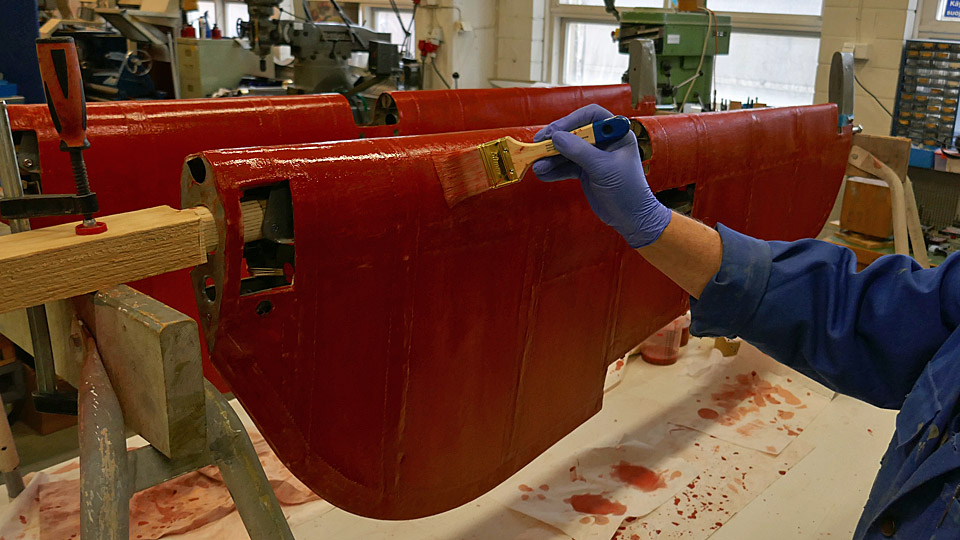
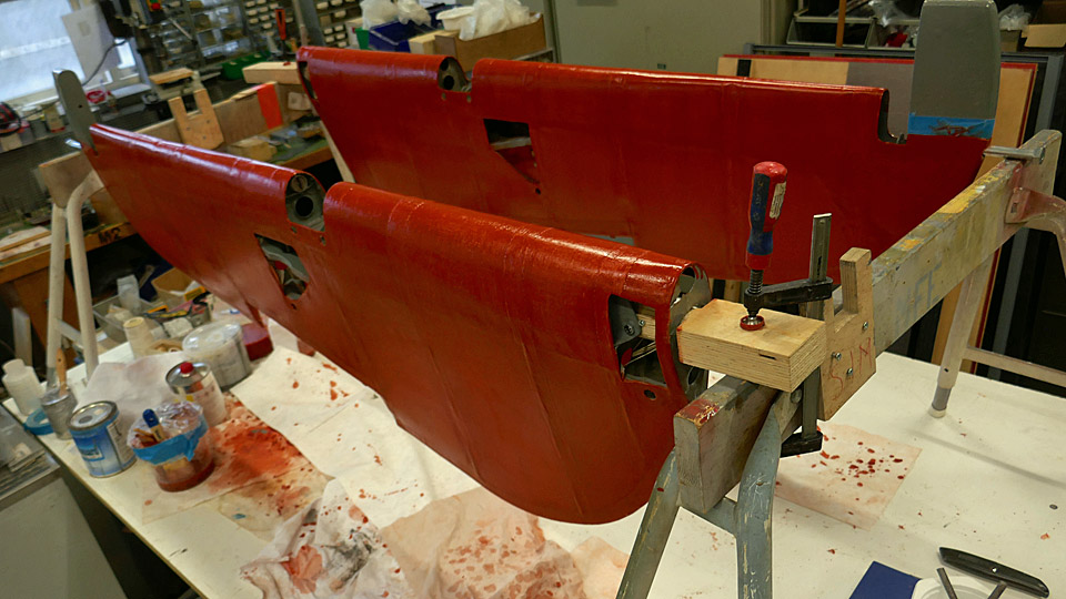
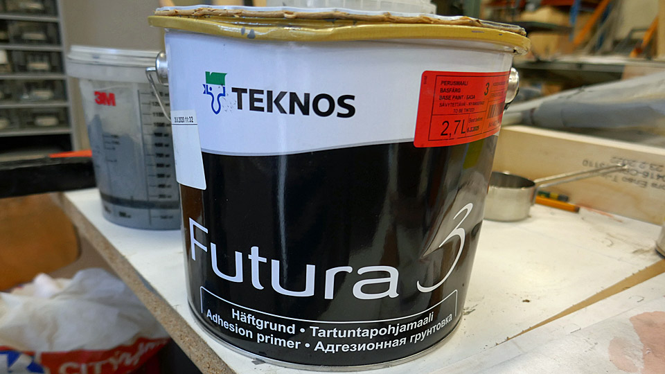
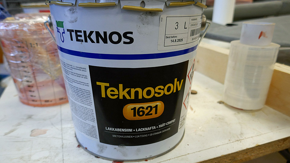
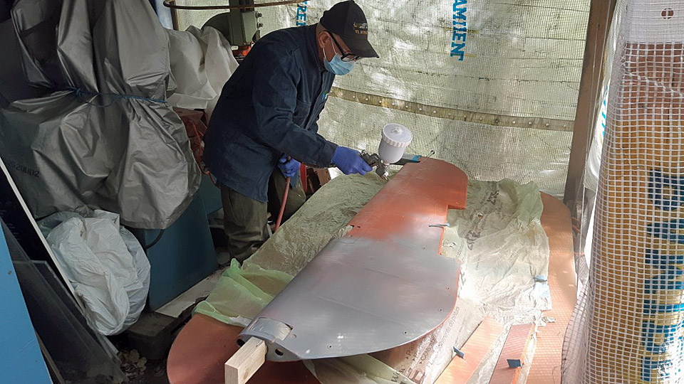
After tightening of the covering fabric, it was time to prime the elevators. TEKNOS Futura3 primer was chosen, and Teknosolv 1621 white spirit as thinner.
The priming was done by spraying, using the Futura 3 which was thinned to 75%. Before spraying, the openings in the elevators were covered to prevent the paint to get inside the elevators.
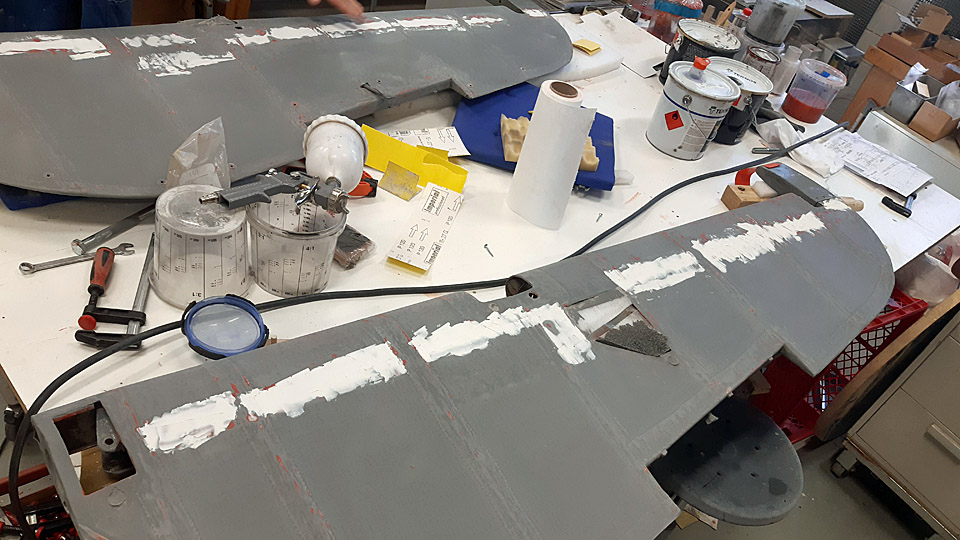
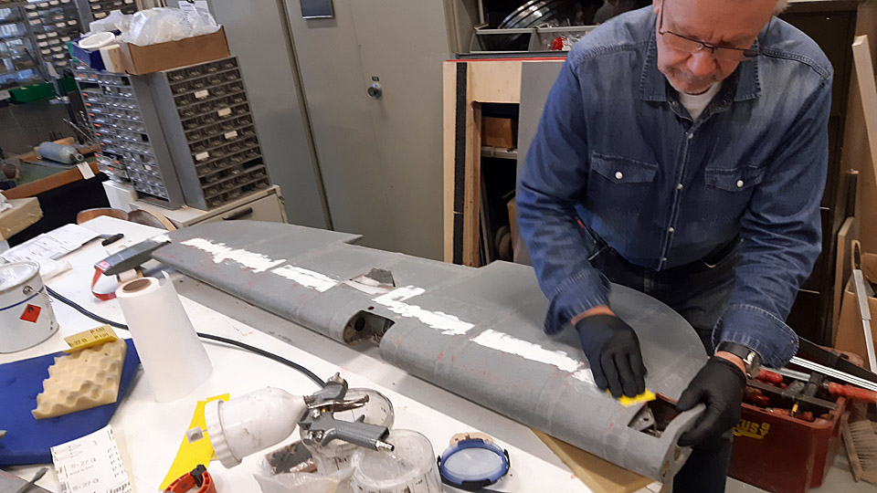
After spraying, the surfaces were sanded manually. At the same time, it was noticed that there was a slight depression on the trailing edge side of the elevator, along the whole length of it. Filler was applied to this area. After the filler had dried, the area was sanded to the form of the curvature of the elevator profile.
The second layer of the primer was also done with 75% Futura 3 primer. After spraying the surfaces of the fabric were sanded smooth. Special care was taken to the serrated edges of the protective strips on the sewn seams, so that the serrated edges could be sanded, so that they no longer feel like uneven spots on the surface of the fabric.
The elevators of the Myrsky have now been primed twice. We are debating that a possible third layer of primer could be sprayed on the surface of the elevators. Photos: Lassi Karivalo Translation: Matti Liusvaara. |
|
Avainsanat: aviation history, restoration, Tuesday Club, MY-14, VL Myrsky |
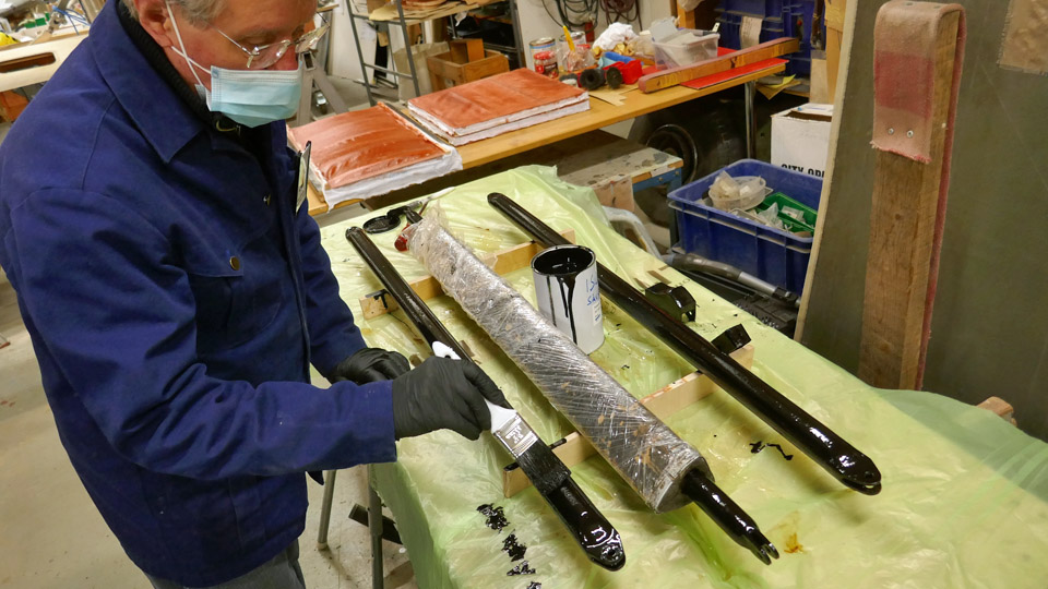
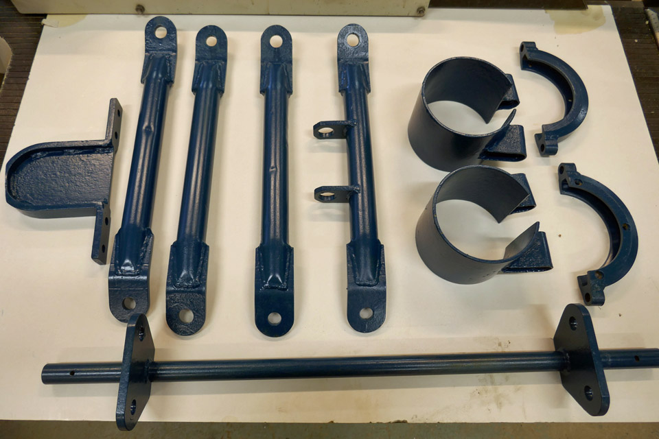
Super Caravelle tow bar restoration completedTorstai 12.5.2022 - Tuesday Club member Owned by the Aviation Museum Society and badly rusted, the Super Caravelle towbar was taken in the Tuesday Club for restoration six months ago. For the restoration the bar was dismantled. By March the parts had been cleaned of rust, so the surface treatment of the tow bar, that’s to say painting, could be started.
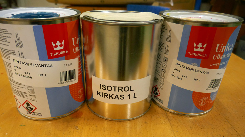
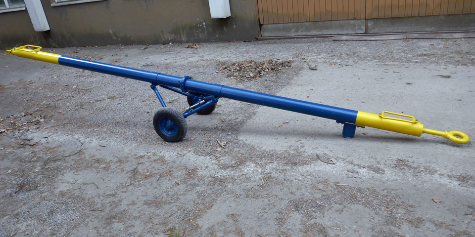
The towbar is to be painted in original colours of the Finnair era. The main colour has been “Finnair Blue”, but the ends have been painted with yellow high visibility colour. The original hues could be determined by a firm called “Pintaväri” from the paint residue still to be seen on the surface of the steel. The blue was found to be NCS S 6030 B and the yellow RAL 1023. For the paint, Tikkurila Oy manufactured Unica Outdoor furniture paint, was chosen. As the primer, a translucent Isotrol-lacquer was chosen, as it protects the parts from rusting.
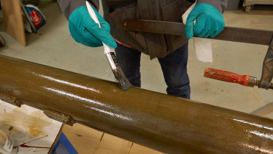
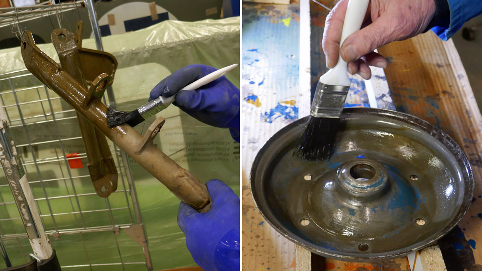
Before the surfaces were treated with the primer, they were wiped with Sinol-water solution. After this, the parts of the tow bar received as a primer the translucent Isotrol. After the Isotrol had dried, the surfaces were lightly sanded, vacuum cleaned and wiped again with Sinol-water solution.
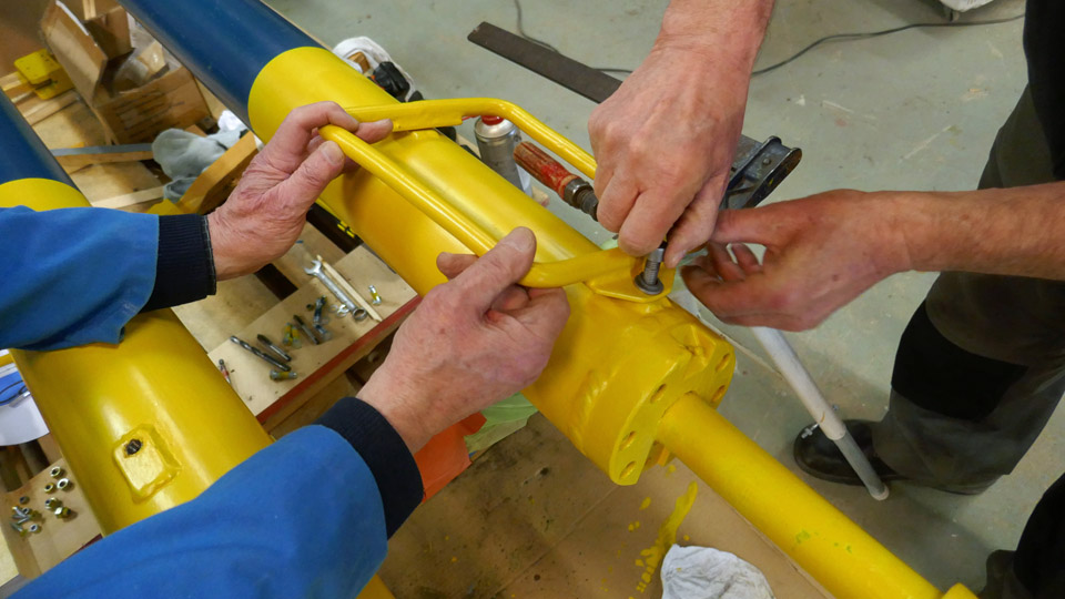
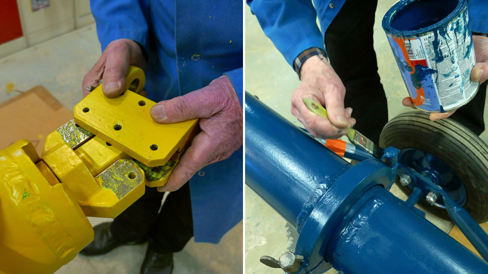
First the ends of the tow bar were painted yellow. The length of the high visibility area at the loop end of the tow bar has been 50 cm, and at the connector end 73 cm. The area to be painted was bordered with painter’s tape. The loop headed towing bar was also painted yellow and the nose gear connector at the other end likewise.
When painting with the yellow, it was noticed that the yellow paint covers insufficiently, especially when painted on the dark steel surface which has been painted with translucent Isotrol lacquer. The yellow had to be applied up to five layers, before the result was satisfactory. The inability to cover is an annoying feature of yellow paint. The yellow paint would have covered better, if we’d had the good sense to use light grey Isotrol to prime these parts. On the other hand, when we started to paint the parts of the bar with blue Unica paint, we noticed that the paint had an excellent cover from the first layer on. The covering abilities with the same paint differ greatly depending on the difference of the pigment.
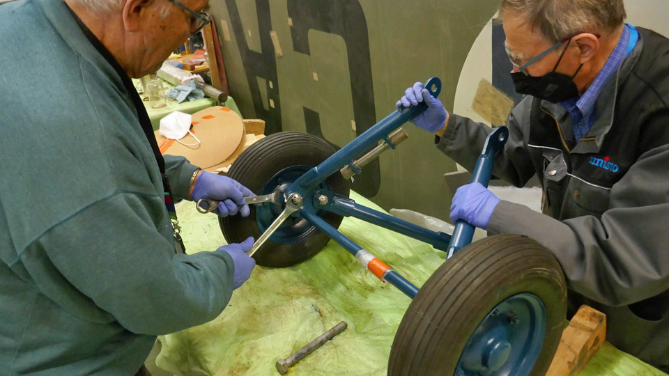
When all the parts of the towing bar had received a new coat of paint, the assembly of the towing bar started. First the wheels were connected to the axle, after which the support arms of the wheels were fixed from the lower ends to the flanges in the wheel axles. The wheels were fastened from their support arms to the two broad flanges. At the same time with assembling the wheels, handlebars were screwed to both ends of the tow bar, to lift or move the tow bar by hand.
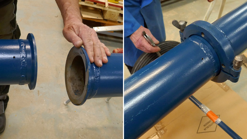
Now we were ready to attach the halves of the 4,7 m long bar to each other. They were locked into each other with a collar tightened around the attachment point. At the same time the upper ends of the support arms of the wheels were fastened to the collars on the tow bar.
The camber and caster angles of the wheel support arms were adjusted to make the wheels go straight. A connecting piece was fastened to the aircraft end of the tow bar, from which the bar was connected to the nose gear with a pin. Finally the bolt and nut ends of the support arms of the wheels were painted blue.
The rust covered towbar of the Super Caravelle had been restored in the Tuesday Club to its original livery. The change compared to the rust covered one was remarkable. The towbar will still get an original white Super Caravelle-like logo on its side. Somehow, it’s fitting to this time, that the towbar is in the Ukrainian colours. Photos: Lassi Karivalo Translation: Matti Liuskallio. |
|
Avainsanat: aviation history, restoration, Tuesday Club, Caravelle |
Tuesday Club started its spring season with full capacityTiistai 1.3.2022 - Tuesday Club member Suomeksi The Tuesday Club was not able to start its spring season in January because the amount of people allowed to work in the restoration workshop of the Finnish Aviation Museum was still limited due to the Covid-19 pandemic. Only the restoration work on the Myrsky MY-14 could be continued in January. Only half a dozen Tuesday Club members could work at a time, wearing masks. In the beginning of this year the Myrsky project has concentrated on the NACA-ring and the port wing landing gear doors, as well as finishing the Myrsky demo-wing before the Myrsky restoration exhibition will be opened.
Along with the Myrsky restoration work, a couple of Tuesday Club members have been working to finish the painting of the Mil Mi-8P (HS-6) helicopter tail boom stabilizers and to take the large parts of the Super Caravelle towbar to be sandblasted. The tyres of two 1920s aircraft wheels have also been dismantled so that the wheels can be repaired. These wheels have been received from the Finnish Air Force Museum to be assembled on the Caudron C.50 (CA-50) aircraft.
As the national Covid-19 restrictions have been lifted due to the decreased health risks caused by the pandemic, it was agreed with the Finnish Aviation Museum that the number of people working in the restoration workshop can be increased. This enables us to launch other Tuesday Club activities in addition to the Myrsky work. On February 23rd we continued from where we stopped before Christmas, particularly with the Caudron C.59 conservation and the Super Caravelle towbar restoration. We still work in two groups of 10 Club members, one group on Tuesdays and the other on Wednesdays. The Myrsky team, with less than 10 members, is working on Tuesdays, Wednesdays and Thursdays.
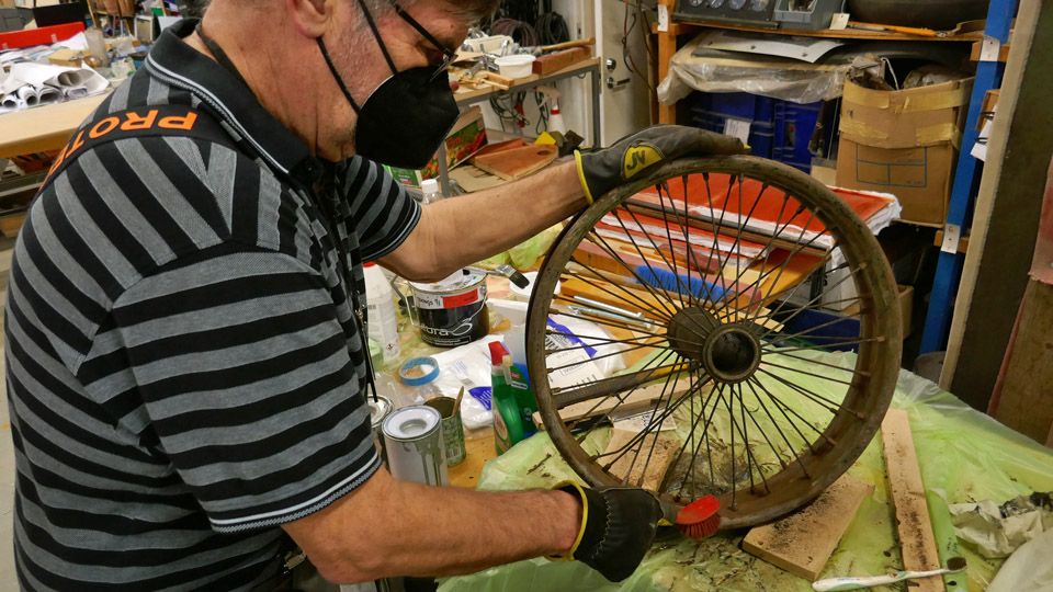
The coming weeks will be spent in cleaning the parts which were dismantled from the Caudron’s fuselage, and after that the parts will be painted. Two landing gear wheels were received from the Finnish Air Force Museum for the Caudron. The wheels and spokes are cleaned from dirt, grease and rust. Mechanical and chemical methods are applied.
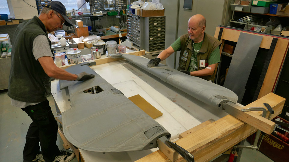
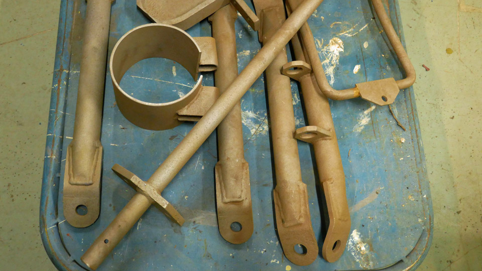
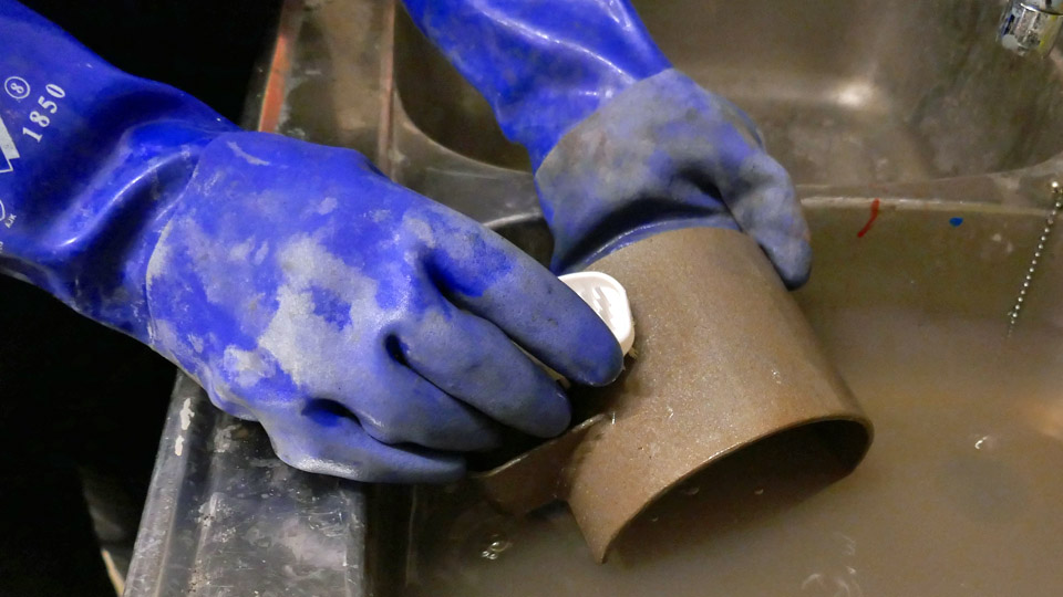
The Caravelle towbar has been dismantled and all dismantled parts have been cleaned of rust, either with phosphoric acid or by sandblasting, and the painting work can be started. Before painting, the sandblasted parts were washed to remove the sand dust, which remained on the surface. Then the parts were carefully dried, using compressed air. Some parts have already been painted with clear Isotrol varnish which will prevent rust. Photos: Lassi Karivalo Translation: Erja Reinikainen. |
|
Avainsanat: aviation history, restoration, VL Myrsky, MY-14, Caudron C.59, CA-50, Mil Mi-8P, HS-6, Super Caravelle |
Situation update from TikkakoskiTorstai 24.2.2022 - Reino Myllymäki A visit to Tikkakoski on February 11th made it possible to write one situation update, that was published on February 20th, 2022. But on February16th the restoration group at Tikkakoski sent more updates, mainly pictures.
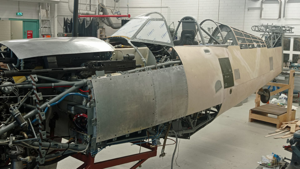
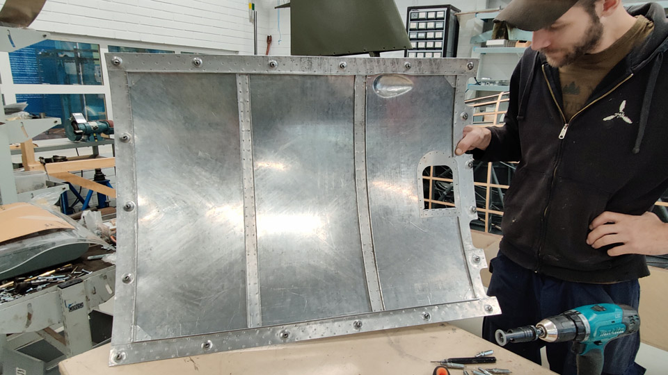
The covering sheets around the wind screen are nearing to being completed. Mind you, of the original sheets only one survived, around the root of the antenna. All the others are made of the blanks, constructed by Antero Flander. Riveting was a huge job, 2500 flush rivets! Now the first covering sheets have been primed and surface painted, although the olive green will yet be revived and the final lines between the colours will be repainted with the camouflage painting.
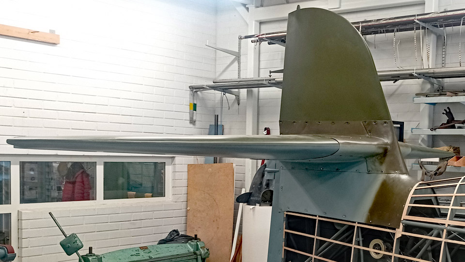
The tail fairings have also received priming and surface coats of paint. Fitting them in place can start now, as the stabilizers are at Tikkakoski for test fitting.
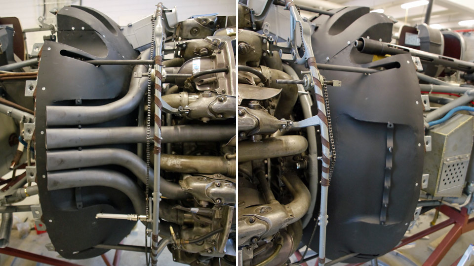
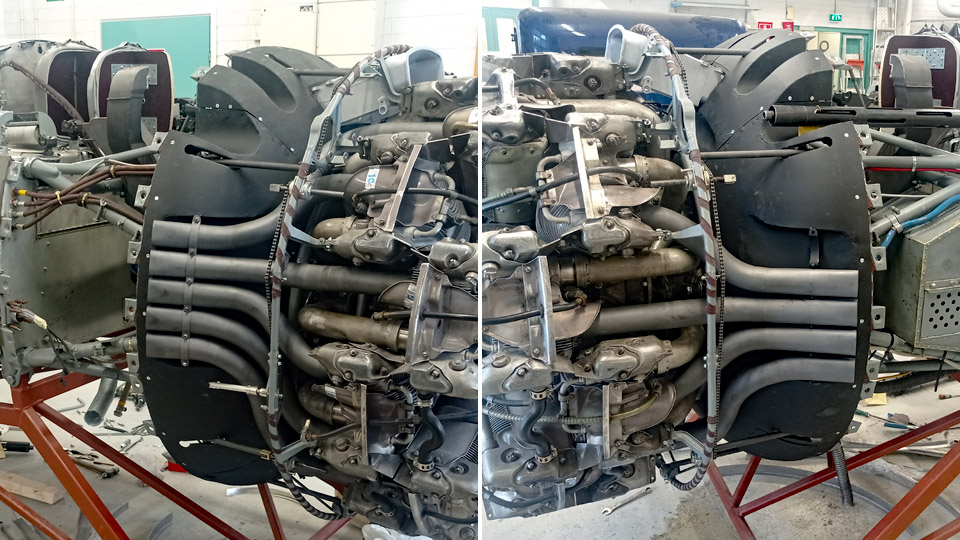
The fire plate has been painted matt black and refitted. The disassembled exhaust pipes, too, have been refitted on February 11th.
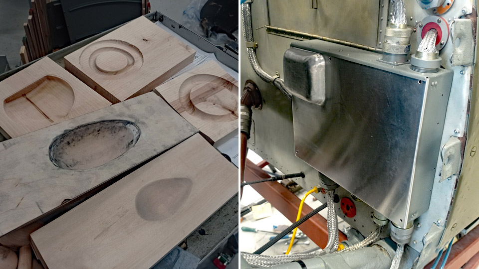
The front firewall switch case has been fitted with a cover, on which a” bulge “ was made by forging against a wood last. Other wood lasts have been made for forging, partly with CNC-milling, partly by hand crafting. The “bulges” by the machine gun breech block solenoids that look small in photos, are in fact quite large. They, too, have been made by forging against wood lasts.
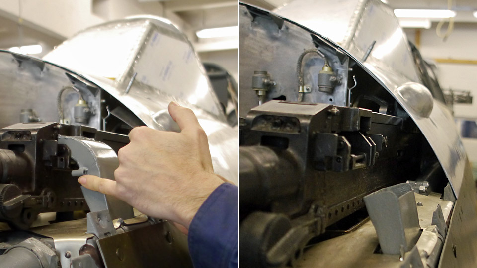
The “bulge sheets” by the outer machine guns have been constructed in such a manner that the breech cover can be opened and closed without taking the whole sheet off. On top of that, it was observed that the cartridge chutes of the outer and inner machine guns differ from each other in the extent of material thickness. They were probably designed by different draughtsmen.
Photos: The Air Force Museum, unless otherwise mentioned. |
|
Avainsanat: aviation history, restoration, MY-14, VL Myrsky |
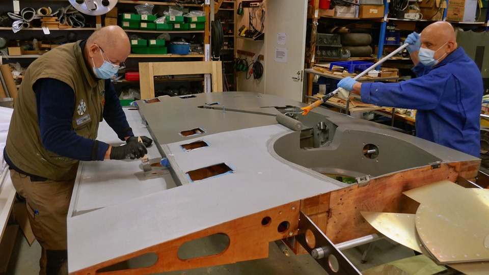
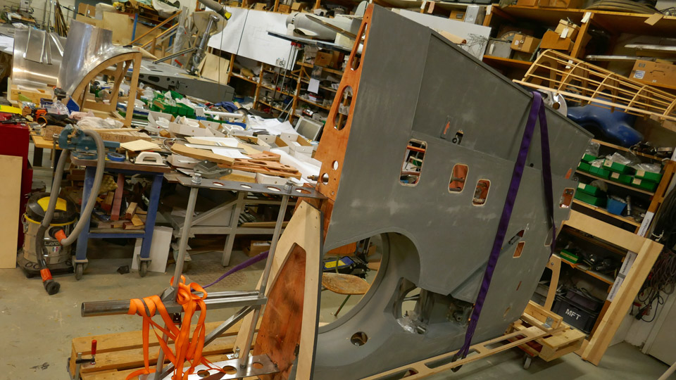
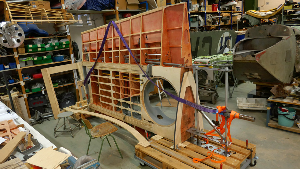
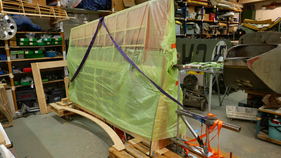
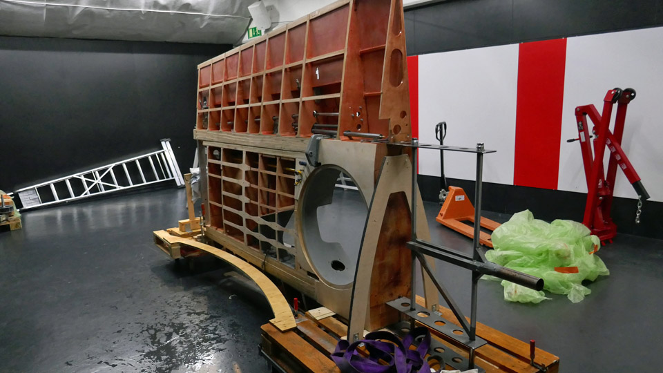
Myrsky's demo wing was moved to mid hall of Finnish Aviation MuseumTiistai 22.2.2022 - Tuesday Club member When the underside of the demo-wing, built in the VL Myrsky II (MY-14) restoration project, had been painted with Futura 3 adhesive primer, it was ready to be moved from the restoration workshop of the Finnish Aviation Museum into the museum’s mid hall. An exhibition about the VL Myrsky II restoration project will be built in the mid hall. The demo wing will be used in the exhibition to show the museum visitors what the wood-structured wing and the equipment were like in the Finnish WWII VL Myrsky fighter. All the equipment of the Myrsky’s wing have been assembled into the demo wing, including landing gear, operating mechanisms of the ailerons and the hanger for the auxiliary fuel tank / bomb. To allow a better view of the wing structure, the upper side of the wing has not been covered with plywood.
The demo wing includes a 2,5-metre section of the starboard wing and a one-metre root part of the port wing. The demo wing was used for testing how to build the Myrsky wing’s root part before starting to build the actual wings for the Myrsky MY-14. Now the demo wing will be used as a showpiece.
For moving the demo wing into the exhibition, pallets with wheels were fastened at both ends of the wing, which weighs nearly two hundred kilos. The demo wing was supported on racks made of steel and plywood, fastened on the pallets. The wing was locked into a vertical position with the leading edge downwards.
Having the wing in this position was the only way to manoeuvre the wing through the flight simulator room in the Aviation Museum’s mid hall and into the space reserved for the exhibition in the mid hall. Even this way the wing had to be wriggled through the hall inch by inch.
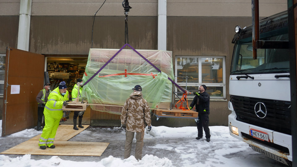
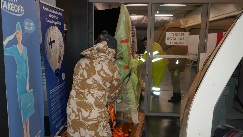
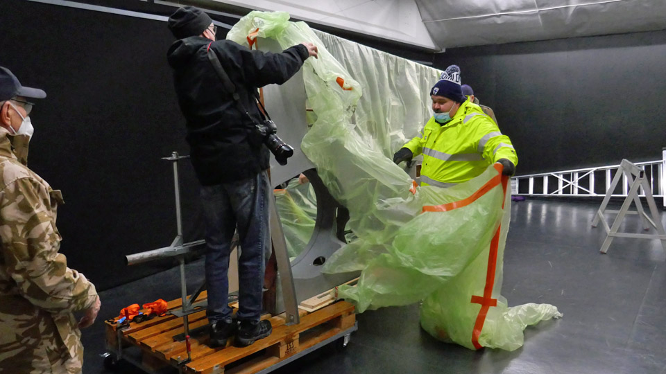
The wing was moved from the museum’s restoration workshop to the mid hall’s outer door on a lorry with a hoist. The transfer took place on a very rainy day, so the wing was protected from the rain by wrapping it in plastic.
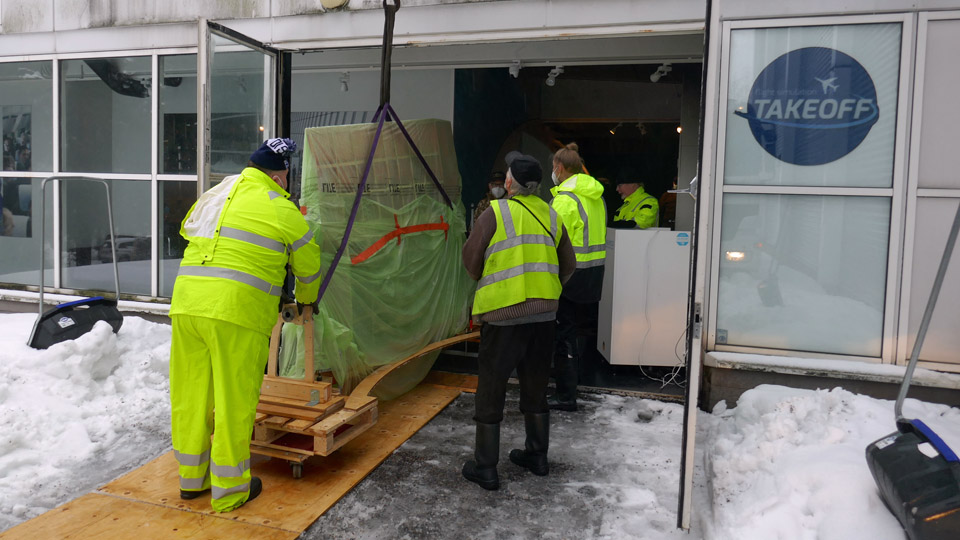
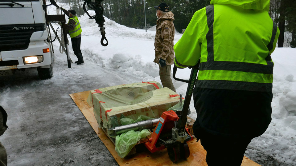
The wing package was pushed out of the restoration workshop on the pallets with wheels, then the hoist straps were fastened. The wing was lifted, using the hoist, and moved onto the bed of the lorry. The lorry transported the demo wing to the mid hall’s outer door. There the wing was lowered in front of the door with the hoist, then it was pushed on the pallets through the door and into the simulator room in the mid hall. The one-metre section of the port wing was also brought to the mid hall on the same lorry.
In the simulator room the four-metre demo wing on its pallets was manoeuvred between the simulators until it was at a right angle facing the doorway to the mid hall exhibition area. The demo wing was gently pushed into the space which is reserved for the Myrsky exhibition. It was a close call, because there was only an inch between the pallets and the door frame. When the demo wing had reached its destination, the rain protecting plastic could be removed.
Now the demo wing will be prepared for exhibition. First the pallets will be removed, then the starboard and port side wing halves will be joined, and the landing gear will be assembled into the starboard wing. There will be also a Myrsky’s rear fuselage in the exhibition, with the wooden vertical and horizontal stabilizers, which were built in the Myrsky MY-14 restoration project, and the original metal elevators will be assembled, too. In the Myrsky restoration project the Aviation Museum Society’s Tuesday Club has concentrated, among other things, on the wings, tail, landing gear, oil cooler and engine cowlings. The Finnish Air Force Museum has been working on the fuselage restoration. Hopefully the MY-14 restoration will be completed next year. Then the genuine Finnish WWII Myrsky fighter would be on display for the public.
The VL Myrsky II restoration project exhibition is open between 5.3. – 31.5.2022 at the Finnish Aviation Museum during its normal opening hours. The exhibition is in the mid hall, used for changing exhibitions, and a museum ticket is needed. The ticket prices are: adults 12 €, reduced groups 6 €, children below 7 years € eur and Museum Card 0 €.
I warmly recommend a visit at the Myrsky exhibition which will open in March. There you will learn about the restoration work of Myrsky MY-14 and about the history of the Myrsky fighter, which was the only WWII fighter of the State Aircraft Factory to reach series production phase. Photos: Lassi Karivalo. Translation: Erja Reinikainen |
|
Avainsanat: aviation history, restoration, VL Myrsky, MY-14, MY-5 |
The stabilizers to Tkkakoski, wheel to VantaaSunnuntai 20.2.2022 - Reino Myllymäki The undersigned had a chance to visit the Air Force Museum at Tikkakoski on Friday Feb.11th 2022. As earlier, the trip had many purposes. The day before yesterday I went to photograph the Sasky aircraft at the Mänttä agency and on Friday the main purpose was to scan the photo albums of Paavo Kahla and Kurt Södergård for the coming Paavo Kahla book.
But since I was at Tikkakoski, I went to see the Myrsky - II project situation. Now I had reason more than usual, because in the boot of the car came the MY-14 stabilizers from Vantaa to Tikkakoski for the fitting of the fairings.
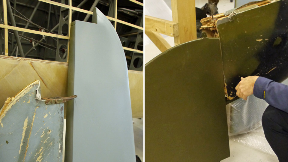
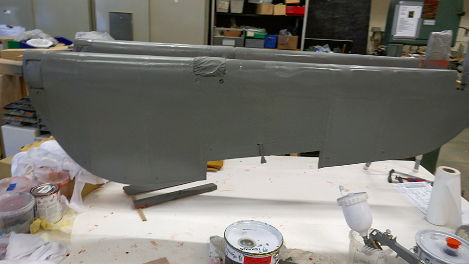
The stabilizers had a coat of paint on the surface, only the black camouflage colour on top of the olive green was missing. The paintwork on the plywood surfaces of the stabilizers seemed very good compared to the original parts, as can be seen in the photos.
Also the fire plate had been painted at Tikkakoski. The matt black doesn’t really show in any photos, and we don’t know for sure, whether the Myrsky aircraft were painted like this, although this is strongly supported by the painting of the VL Humu’s respective parts. Photos: Reino Myllymäki Translation: Matti Liuskallio |
|
Avainsanat: aviation history, restoration, MY-14, VL Myrsky |
About the wheels of Caudron C.59 (CA-50)Lauantai 5.2.2022 - Tuesday Club member The Finnish Aviation Museum and the Tuesday Club have a common subject for conservation; The Caudron C.59 advanced trainer, serial no CA-50, which was in service with The Finnish Air Force. The last flight of the type was in October 1929.
Brought from the Päijänne-Tavastia Aviation Museum in Vesivehmaa to Vantaa for conservation, the Caudron landing gear has genuine 1920’s wheels and tyres. The landing gear has already been taken apart, cleaned of rust and the surface finishing of the parts is under way by the Tuesday Club.
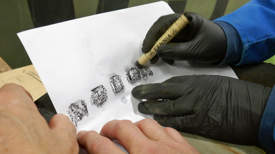
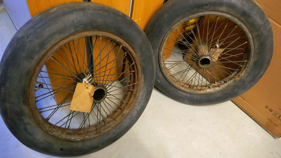
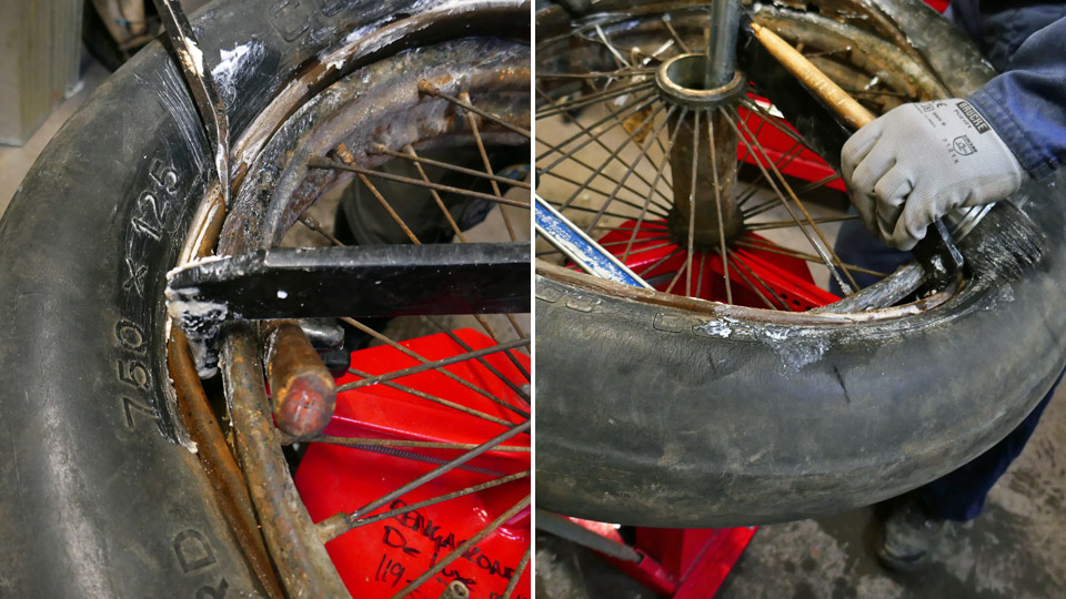
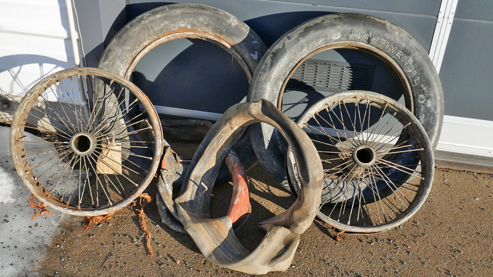
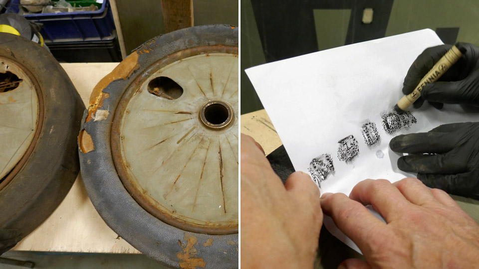
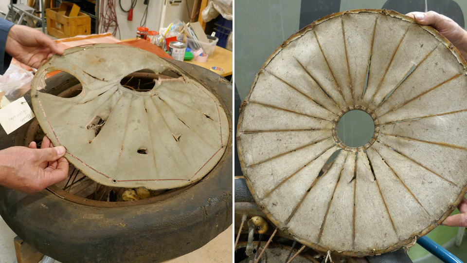
The CA-50 wheels are an odd pair, and the rims and spokes differ from each other. Otherwise the wheels and tyres are of the same size. One wheel turned out to be French with a NEUILLY-AVIATION-AERO 750-125 tyre. The markings on a very dilapidated tyre could only be read with the help of paper and a black grease pen. The tread of the NEUILLY-AVIATION-AERO tyre has been largely peeled off, exposing the canvas under it. The other was a British wheel. Its tyre is a PALMER CORD AERO TYPE 750x125, and it’s hardly in a better shape than the French one, which is probably an original Caudron wheel. For some reason it had been mated with a British wheel. Is it possible that it had belonged to a Martinsyde F.4 Buzzard fighter, which was in service with The Air Force in the 1920’s, as the Caudron was.
Both the inner tyres have been at some point filled with polyurethane filler mass, squeezed in through the valve. This way the tyres have been made to resemble ”solid rubber” when the fuselage was standing on the landing gear on show in the Päijänne-Tavastia Aviation Museum hall.
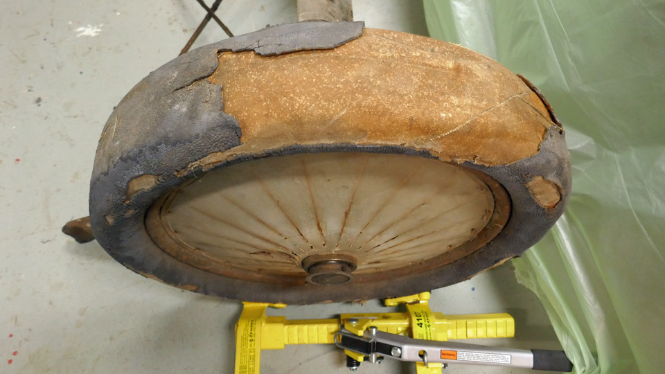
The restoration of these wheels to their original condition was not possible without breaking them because of the polyurethane inside the tyres. So the question arose whether The Air Force Museum at Tikkakoski might have similar, but better 1920’s wheels to install on the CA-50. There was a suitable pair of wheels in Tikkakoski which fitted the Caudron’s axles, with Continental 750x125 AERO CORD tyres and clearly in a better shape. Although they weren’t French. The Finnish Air Force Museum gave the wheels to be fitted to CA-50, so we fetched them from Tikkakoski to Vantaa.
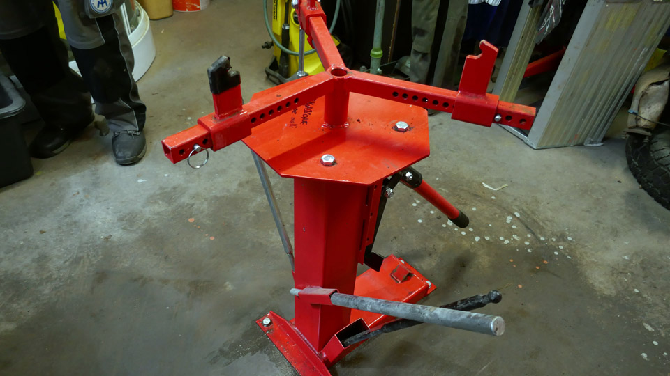
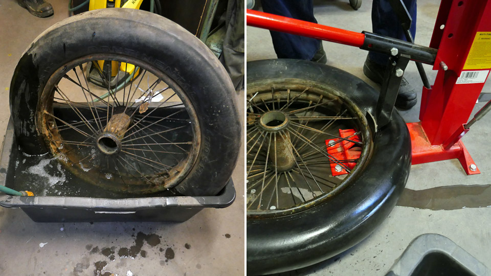
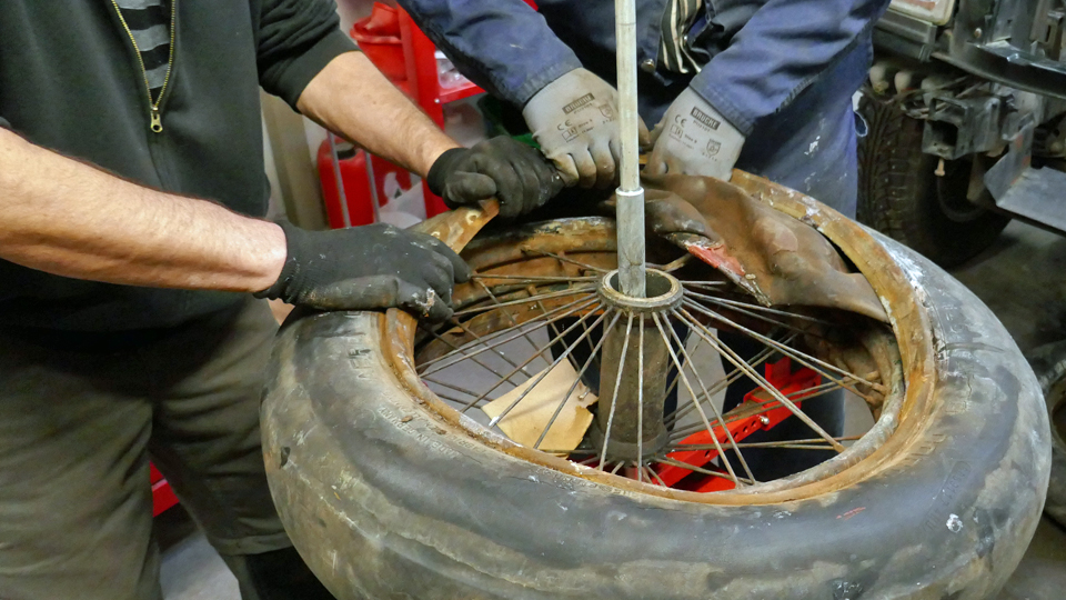
The rims of the wheels with the Continental tyres were covered with a thick layer of rust, so the tyres had to come off. We didn’t take them to a tyre repair shop to be taken off the rims, instead we decided to take them off carefully in a manual tyre working bench in the garage of a Tuesday Club member.
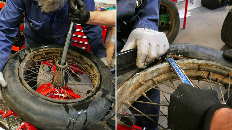
Before starting to detach thy tyre, we warmed the tyre in hot water to make it softer. After a while we took the wheel out of the bath and started the tyre work. First we pressed the edge of the tyre free from the inner edge of the rim where it had got stuck over the period of 90 years of storage. The parting of the tyre edge from the rim was done with a lever in the bench. With the aid of a metal plate in the lever it was possible to free the edge bit by bit and so free it from the rim. In this way both edges of the tyre were freed from the inner edge of the rim.
It was time to separate the tyre. The wheel was lifted on bench and locked there with a metal peg and clasps attached to the wheel rims. With the help of a tyre bar, we opened carefully an opening between the tyre and the wheel rim. Into this opening we pushed a metal rod with a down pointing ball-headed peg at the other end. Propping the metal rod against the metal peg in the middle of the bench and swivelled the ball-headed rod in the opening between the tyre and the rim counter-clockwise. This way the edge of the tyre was managed gradually on top of the rim. Simultaneously we applied lubricant on the edge of the tyre to facilitate the moving of the ball-headed rod between the tyre and the rim.
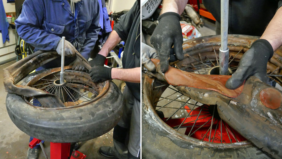
When the other edge of the tyre was on the rim the whole way, we pulled out the inner tube from the inside of the tyre. We noticed that the tube was a veritable patching wonder, because a large part of the tube was covered with patches. It was obvious that there was a shortage of tubes in the 1920’s, because the tube had been so diligently patched time after time.
We turned the wheel on the bench the other way round and in the method described earlier we lifted the other edge of the tyre on the rim with the ball-headed rod. Now we were able to pull the rim apart from the tyre.
These Continental tyres seemed good enough to withhold the air pressure, together with new inner tubes. That being the case, they could be used when moving Caudron CA-50 around. Naturally this must be carefully looked into and tested. When being on show, trestles will be put under the landing gear axles in any case, so the aircraft won’t rest on its tyres.
The next phase will be removing the rust from the inner and outer sides of the rims before painting the rims. This will be done by immersing the rim for 24 hours in 33% phosphoric acid bath. Photos: Lassi Karivalo Translation: Matti Liuskallio. |
|
Avainsanat: aviation history, restoration, Caudron C.59, CA-50 |
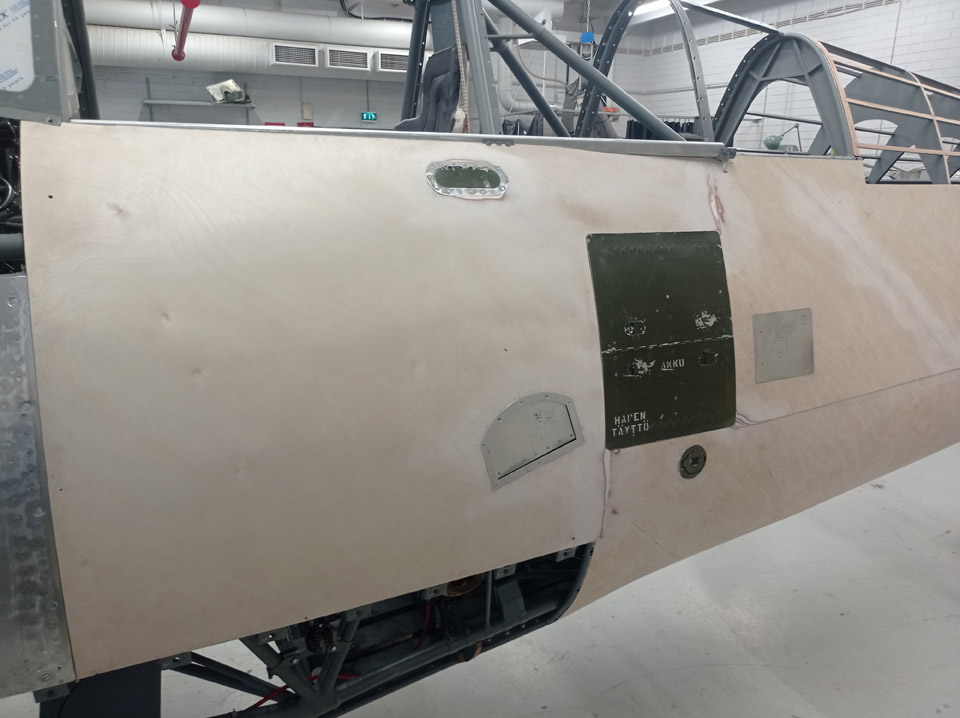
MY-14 fuselage covering with plywood is progressing againSunnuntai 12.12.2021 - Reino Myllymäki According to the photo update from the Air Force Museum from today, it’s plain to see that the covering of the fuselage of MY-14 with plywood is progressing, as well as the making of the aluminium hatches in the covering.
The front fuselage cover hatches have been made of Antero Flander’s blanks, which have been cut to measurements and riveted together. Easier said than done, because there are myriads of 2,6 mm rivets, double the amount compared to the Brewster, so they say. And they aren’t even load carrying parts.
The covering sheets themselves are of 1mm thick aluminium thin sheet. The pins of the Dzus-locks on one of the cover sheets are original VL produce, apart from them the parts are neo products.
The port side plywood covering is about to be finished. Photos: Reino Myllymäki Translation: Matti Liuskallio. |
|
Avainsanat: aviation history, restoration, MY-14, VL Myrsky |
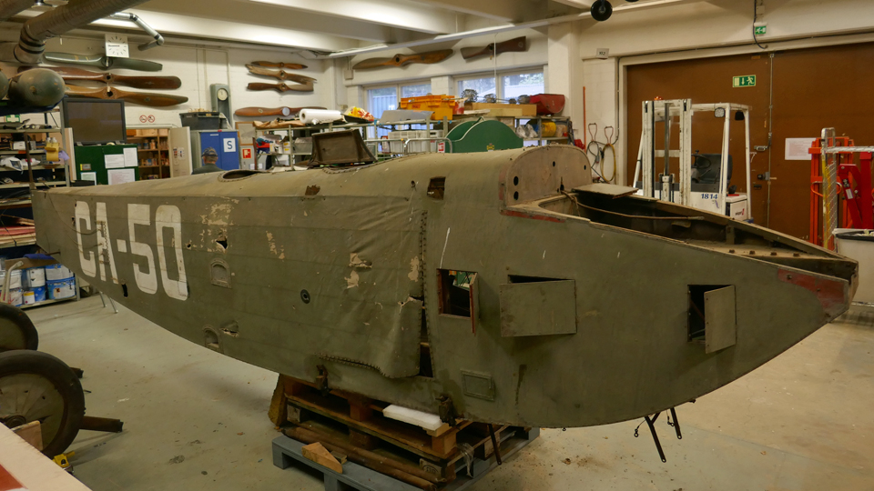
Cleaning Caudron fuselage and removing partsMaanantai 22.11.2021 - Tuesday Club member Preparations for the conservation of the Caudron C.59 CA-50 fuselage are under way at the restoration workshop of the Finnish Aviation Museum. Conservation of the fuselage means that rusting of the metal parts is halted as well as rotting of the wooden parts. The dirty plywood parts of the fuselage will be cleaned, and the badly cracked paint surfaces are being attempted to be revived. The damaged parts of the fuselage will be repaired. The CA-50 fuselage will therefore not be restored to its airworthy condition from the late 1920’s.
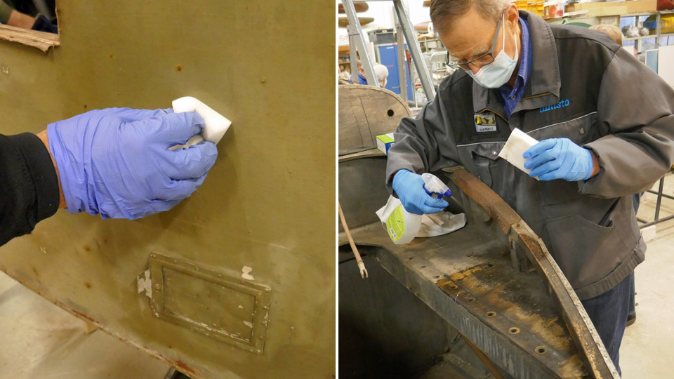
The first task was the cleaning of the plywood surfaces of the fuselage and the empty engine bay. The cracked fabric surfaces will not be touched. At first the surfaces were vacuum cleaned, after that the cleaning went on with a damp wonder sponge, which is well suited for cleaning dirty plywood surfaces. It’s surprisingly efficient and gentle. The engine bay plywood surfaces were so grimy that the wonder sponge treatment had to be renewed a few times. To help in cleaning the surfaces, a solution of water and Sinol was used, administered from a spray bottle.
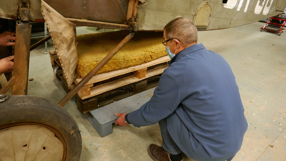
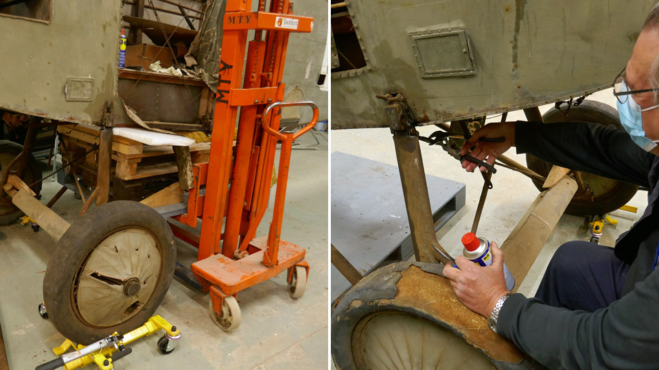
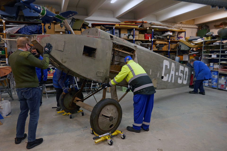
The dissembling of the fuselage parts was started from the landing gear. For that purpose the fuselage had to be lifted on a trestle, so that the landing gear could be removed from under the nose. For the lifting a supporting bed was built from three padded wooden pallets. The trestle was pushed under the fuselage below the cockpit. After this the forks of a stacker were pushed under the supporting bed and the fuselage was lifted on to the supporting bed in order to remove the landing gear.
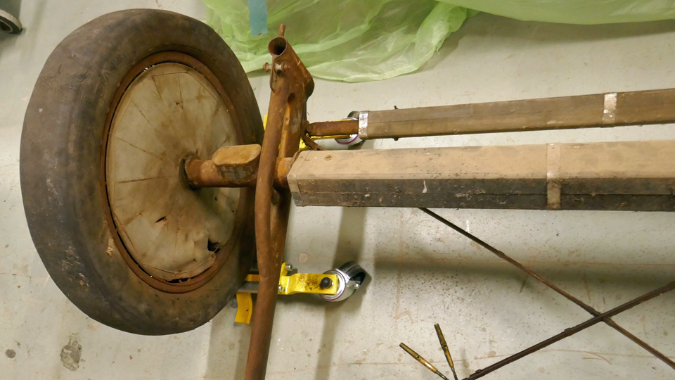
The landing gear diagonal struts were removed next. Although the nuts at the ends of the attachment bolts were thickly coated with rust, they opened surprisingly easily. Even after the Caudron’s 93 years of storage. After the ends of the diagonal strut and the bracing grid had been removed from the fuselage, the landing gear now resting on auxiliary wheels was pushed away from under the nose of the Caudron. The fuselage was then lowered to rest on the supporting bed.
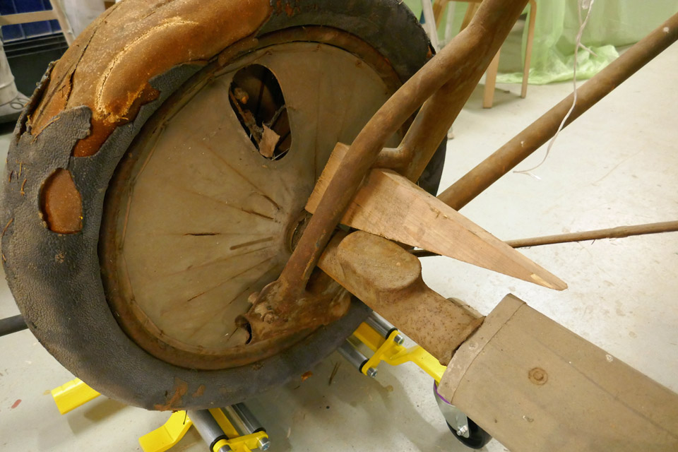
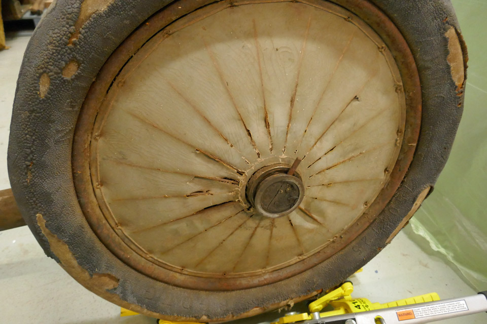
The landing gear was then continued to be taken apart for easier rust removal. First the wheels were detached. Both of them were in a really bad shape. Furthermore, the tyres had been filled with polyurethane at some point. With the help of paper and felt pen the markings on the surface of the tyres were worked out. One of them was found to be French and the other British.
The landing gear wheels were covered in the 1920-1930’s fashion with doped canvas
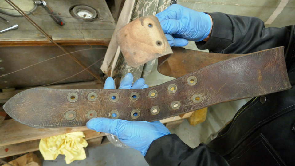
After detaching the landing gear, the Caudron’s cockpit was taken under work. After vacuum cleaning and Sinol-water treatment of the cockpit surfaces the seat belts were removed. On the port side of the front and rear cockpits there are the throttle and mixture levers. They are fastened on the throttle quadrant.
The rear and front cockpit levers are connected with push rods. This was after all a trainer. The throttle and mixture levers were thickly coated with rust. They were taken apart with their push rods to be cleaned from rust. It was noticed, taking the levers apart, that there were traces of nickel plating on the surfaces. Both of the levers and their quadrant have originally been nickeled on the surface. Still to be dismantled from the cockpits are for instance the control columns with their connecting rods and the pilot’s seat in the rear cockpit.
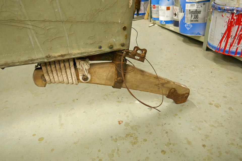
The Caudron has a wooden tailskid. In its rear end there is a metal strengthening to prevent wearing. In the middle of the tailskid there is a bolt which was detached. It fastens the tailskid to the fuselage. The tailskid pivots around this bolt. A length of bungee cord tied around the tailskid and its support in the fuselage acts as suspension for the tailskid. The bungee cord was also detached, so the tailskid has been completely dismantled for further work. Photos: Lassi Karivalo. Translation: Matti Liuskallio. |
|
Avainsanat: aviation history, restoration, Caudron C.59, CA-50 |
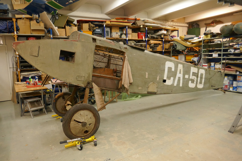
Status of Caudron C.59 (CA-50) after 93 years of storageTiistai 16.11.2021 - Tuesday Club member With the marking CA-50 flown fighter trainer Caudron C.59 was removed from service in the Finnish Air Force in December 1928. The aircraft was stored in Santahamina to wait for restoration. In 1948 CA-50 was transferred to the hangar of Vesivehmaa airport together with many other written off Air Force types. The storage hall like hangar developed into the Päijänne-Tavastia Aviation Museum at Vesivehmaa, when a civilian organization called the Lahti Airlift took charge of it as a museum in 2006. About twenty aircraft, all of them in poor condition have been removed to be restored. Most of them are on display in Finnish aviation Museums and elsewhere, too. Of the aircraft restored by the Tuesday club the I.V.L D. 26 Haukka I and I.V.L K .1 Kurki have been returned back to the Päijänne-Tavastia Aviation Museum.
At Vesivehmaa only the fuselage of the C.59 CA-50 has been on display. It lacks the Hispano Suiza-engine. The wings were stored at first in the nearby former Brewster maintenance space, afterwards in a sea container beside the hall. The Caudron’s lower wings and parts of the tail assembly have been under restoration at the Tuesday Club since the spring of 2019.
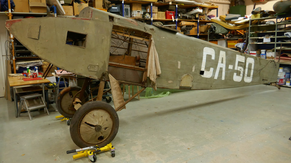
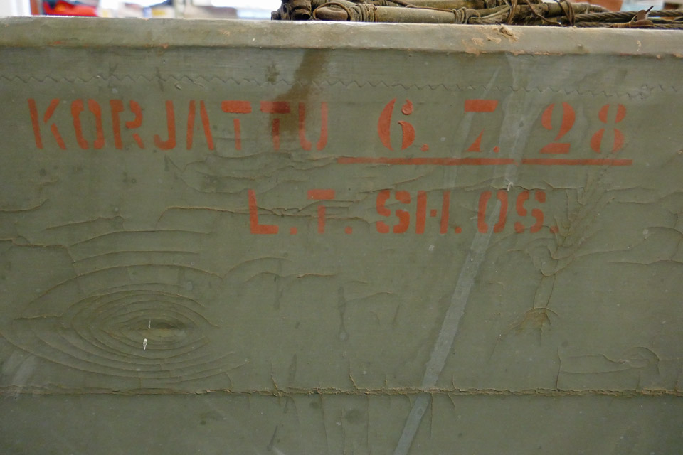
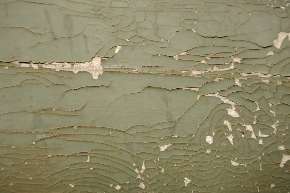
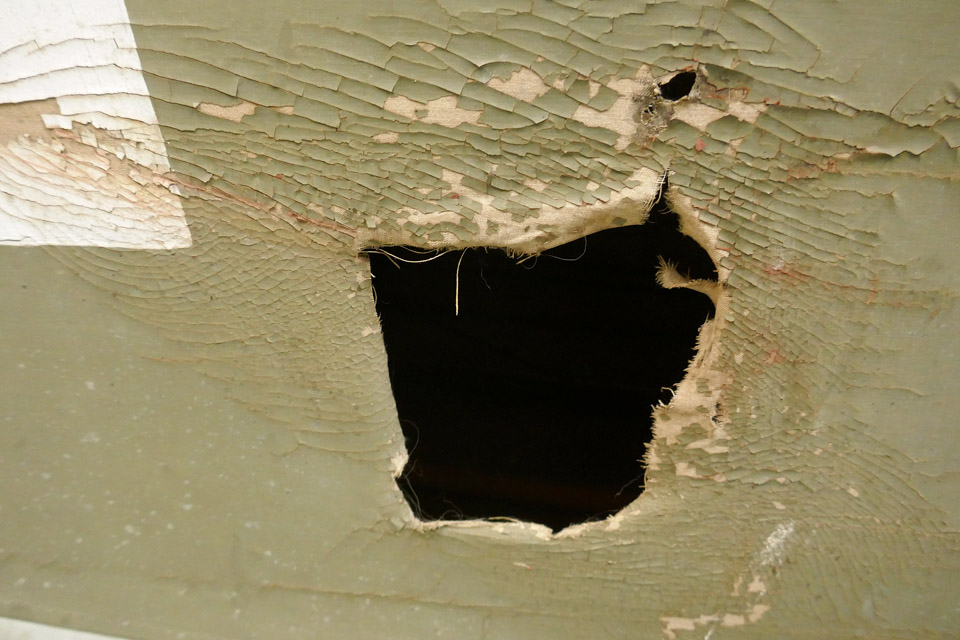
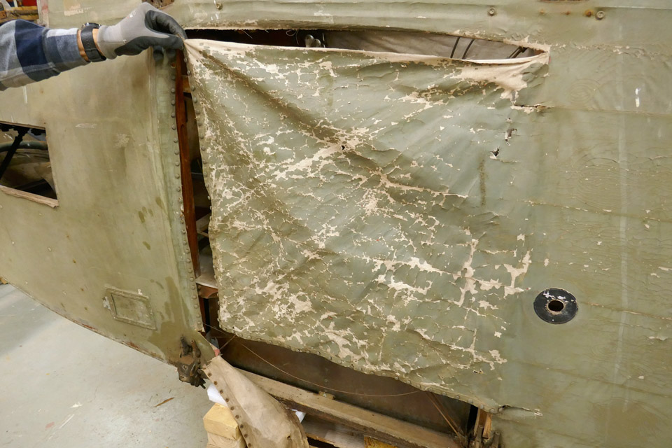
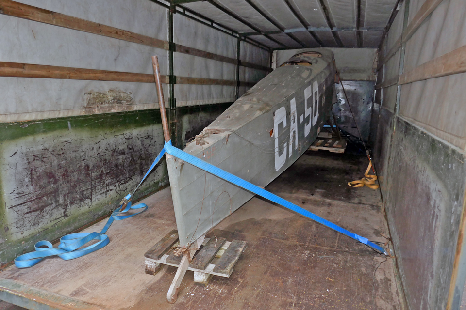
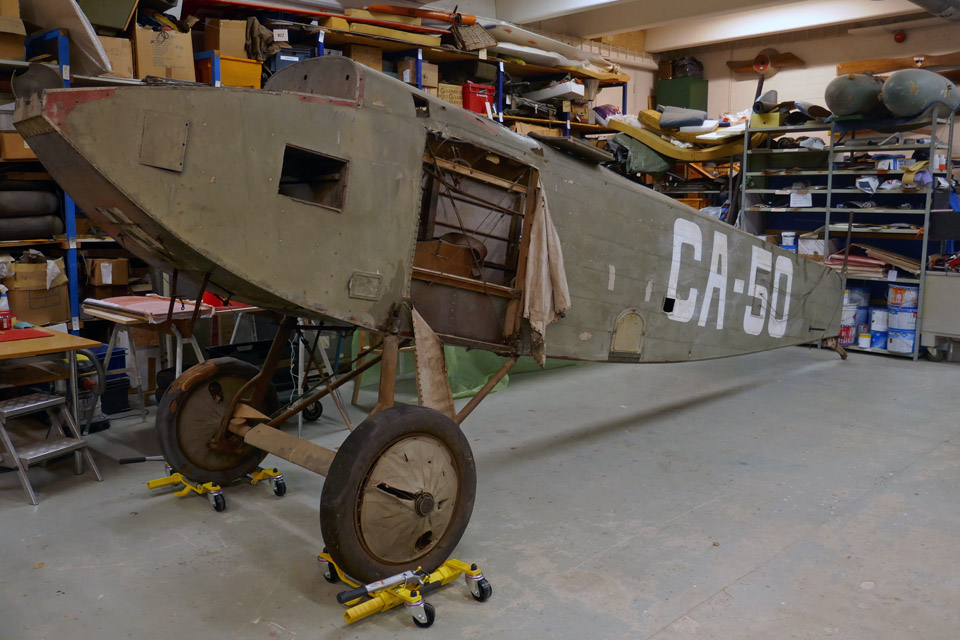
The Caudron CA-50 has been through rough times and even malicious damage during its 93 years of storage. The fuselage of CA-50 when brought to the Finnish Aviation Museum is in a depressing state. All the metal parts are covered with thick rust. The plywood surfaces of the forward fuselage are soiled. In July 1928 the fuselage was totally rebuilt by the State Aircraft factory Santahamina branch. The paint surface has been badly damaged. During the long storage it has badly cracked. There are also many holes and tears in the fabric. On the port side of the fuselage by the cockpit the fabric has been torn open and the paint has badly flaked.
The landing gear which is covered in thick rust is without the suspension bungee cords. The starboard side wheel is French. The tyre bears the text NEUILLY-AVIATION-AERO 750-125. The wheel must therefore be an original Caudron wheel. Part of the rubber surface has been peeled off. On the port side of the landing gear is a British wheel PALMER CORD AERO TYPE 750x125. The fabric spoke covers of both wheels are on the brink on disintegration, because the rusty spokes have caused the fabric touching them to rot away. The tail wheel is structurally sound. The metal parts are covered with rust, but the bungee cord still remains.
The Caudron fuselage is without its Hispano-Suiza 8A engine. In the engine bay are the rows of bolts with their nuts for assembling the engine. The engine bay plywood surfaces are covered with thick dust and dirt. Outside, underneath the engine bay is the rusted assembly frame of the Lamblin radiator. The radiator is missing. On both sides of the nose there are several inspection hatches. They are functioning, but the hatches lack the Fokker pins to secure them.
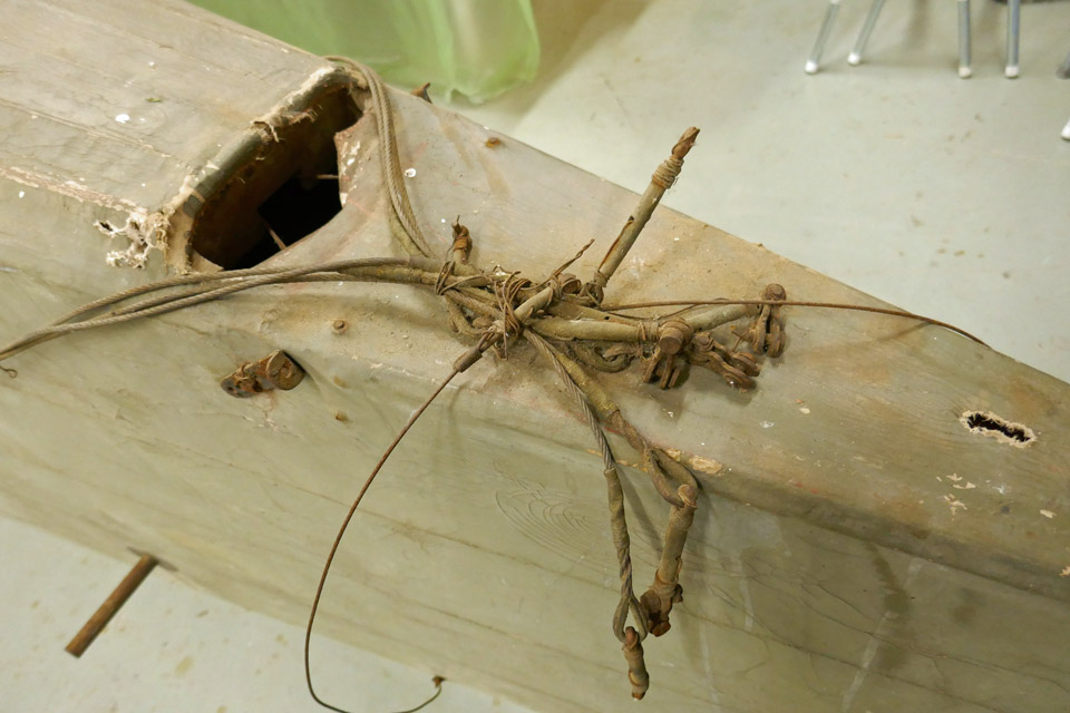
The steering wires from the cockpit to the tail are rusty and they have been tied to a bunch on the fuselage. There are no instruments in either of the cockpits. They have been probably dismantled when the aircraft was written off and stored. The pilots’ rattan seats remain. There’s no control column in the front cockpit. The rear cockpit has one. Both cockpits have the rudder pedals in place. On the left wall of both cockpits the throttle and mixture levers and their connecting rods are all covered with thick rust. There’s plenty on muck and dirt on the rear cockpit floor.
Our first task in the Tuesday Club is to clean the plywood surfaces and engine bay of the dust and dirt and clean up the cockpits. The fabric surfaces will not be touched for the time being because the badly cracked surface, when touched, will easily lose more bits of paint. Photos: Lassi Karivalo Translation: Matti Liuskallio. |
|
Avainsanat: aviation history, restoration, Caudron C.59, CA-50 |
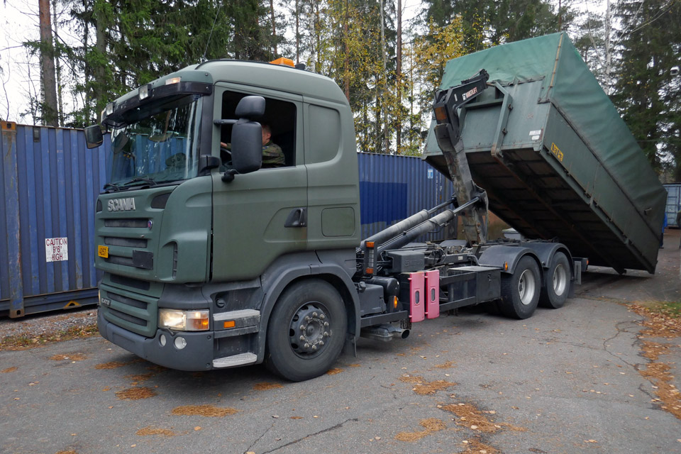
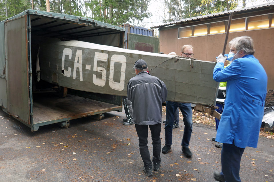
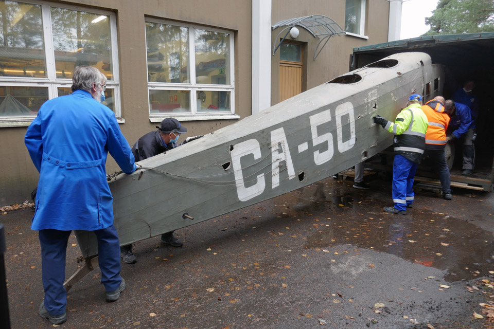
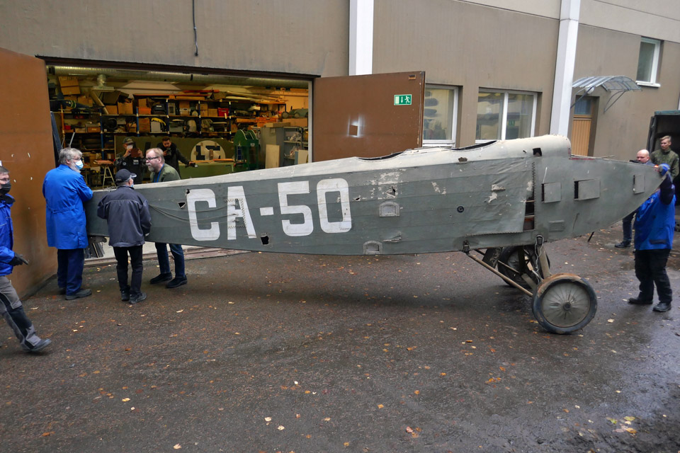
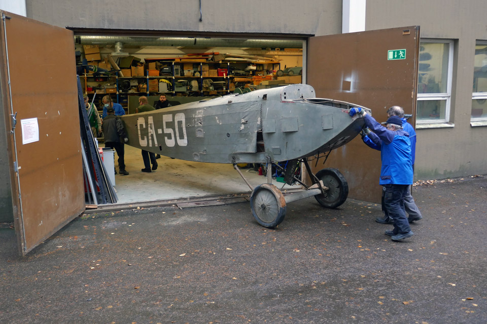
Fuselage of Caudron C.59 came to Finnish Aviation Museum from VesivehmaaSunnuntai 31.10.2021 - Tuesday Club member On Tuesday, October 26th the fuselage of the Caudron C.59 (CA-50) arrived by the Defence Forces transportation at the Finnish Aviation Museum from the Päijänne-Tavastia Aviation Museum at Vesivehmaa.
The Caudron’s fuselage is in poor condition, and it was brought to the Finnish Aviation Museum to be restored by the Tuesday Club. The Caudron’s lower wings and its tail parts have been under work at the Tuesday Club since the spring 2019. The Covid-19 pandemic interrupted the restoration work in March 2020, but from the beginning of September 2021 the work has been continued in the restoration space of the Finnish Aviation Museum.
Now that the fuselage has arrived, the first task is to make an inventory of its present condition and to make a restoration plan for it. The principle in the restoration work is that as much as possible of the original fuselage will be preserved. The rusty parts and equipment will be restored, the broken items will be repaired and the parts which are beyond repair, will be rebuilt. One of the challenging items in the restoration of the Caudron’s fuselage will be the badly cracked painted fabric covering on the fuselage.
The two-seater fighter trainer Caudron C.59 was in use in the Finnish Air Force in the 1920s. In late 1923 the Air Force purchased three Caudron C.59 aircraft to be used in the advanced training of fighter pilots. The CA-50 is the only one which has been preserved. It is most likely the only remaining Caudron C.59 aircraft in the world. The CA-50 flew its last flight in the Air Force on October 1st, 1929 – which was 90 years ago. Then the aircraft was written off and stored to be placed later in a museum. The aircraft was stored at Santahamina until the end of the 1940s, then it was moved – along with several other old aircraft waiting to go into a museum – into the WW2 aircraft hangar at Vesivehmaa airfield. Today the hangar is the home of the Päijänne-Tavastia Aviation Museum.
In two years, it will be 100 years from the Caudron C.59 aircrafts’ arrival in Finland. We are wondering whether if it would be possible to complete the restoration of the Caudron CA-50 before that? Photos: Lassi Karivalo Translation: Erja Reinikainen. |
|
Avainsanat: aviation history, restoration, Caudron C.59, CA-50 |
Filler ring and supporting ring of Myrsky?s NACA-ringMaanantai 25.10.2021 - Tuesday Club member The NACA-ring of the VL Myrsky II is complicated to build. Fortunately the most difficult phases of work have already been completed at the Tuesday Club when building the ring for the Myrsky MY-14 engine, which is under restoration. When the NACA-ring and its parts have been chromated and the fastener consoles, among others, have been fastened on the inner surface of the ring, the NACA-ring can be test assembled on the Pratt & Whitney R-1830 engine, which is available at the Finnish Aviation Museum. It is rather fortunate that this engine is on display at the Aviation Museum and there is no need to travel for the test assembly all the way to Tikkakoski, where the Pratt & Whitney engine has already been assembled on the MY-14 fuselage, under restoration at the Finnish Air Force Museum. The engine, which is available at the Finnish Aviation Museum, has been on a DC-3 but it suits well for the test assembling of the Myrsky’s NACA-ring.
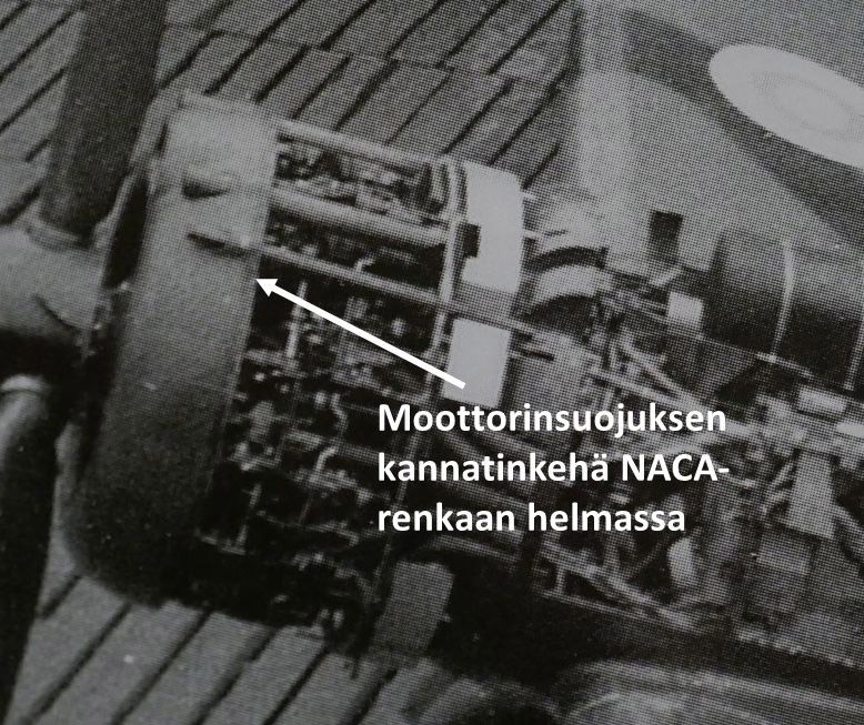
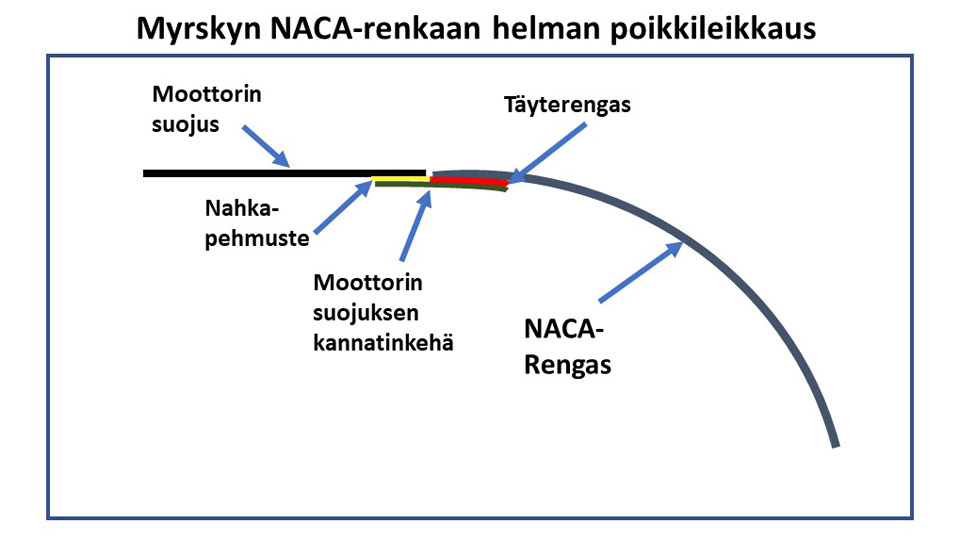
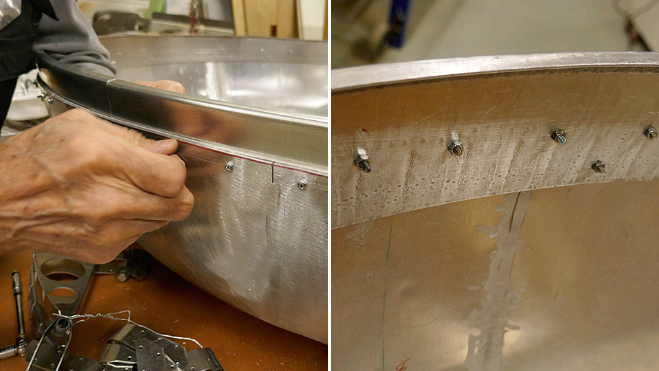
The Tuesday Club team has been working lately on the filler batten ring (täyterengas), which will be fastened on the edge of the NACA-ring (NACA-rengas), as well as the supporting ring (moottorin suojuksen kannatinkehä) for the engine fairing. The supporting ring is fastened on the filler ring and its edge extends 30 mm outside the NACA-ring’s edge. The supporting ring forms a base outside the NACA-ring’s hem for the edge of the engine fairing. The supporting ring is covered with leather (nahkapehmuste) to absorb the resonance between two aluminium surfaces, which is caused by the engine.
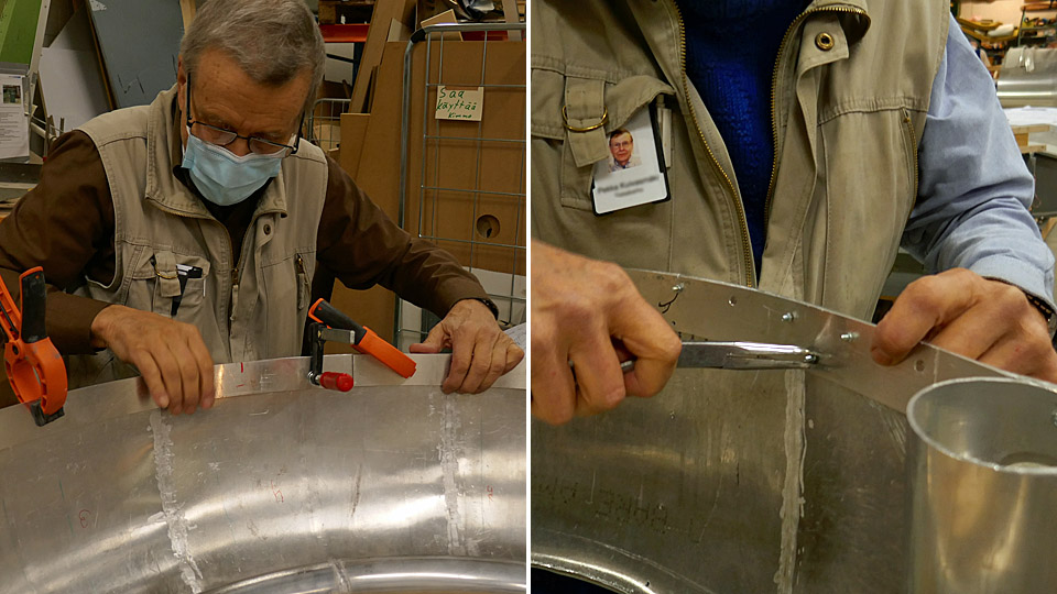
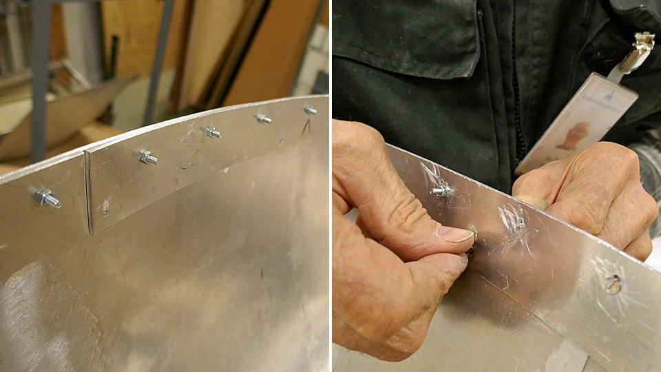
First the filler ring, a 40 mm wide ring cut from 2,5 mm thick aluminium sheet, was fastened on the edge of the NACA-ring. The filler ring was shaped to match the curvature of the NACA-ring’s edge and preliminarily fastened on it with clamps. Then the filler ring was fastened with small bolts. When the ring was firmly in place, the bolts were replaced with flathead machine screws so that the surface of the filler ring is smooth when the supporting ring is assembled on it. Eventually both the filler ring and the supporting ring will be riveted on the NACA-ring.
85 mm wide strips were cut from 1,5 mm thick aluminium plate for constructing the supporting ring. One edge of each strip was bent to form a small gutter. Then the strips were shaped against the filler ring to match the curved shape of the NACA-ring. In the shaping process the supporting ring is also pressed tightly against the filler ring surface. When this had been achieved, holes were drilled through the supporting ring and the filler ring, and the supporting ring was fastened on the filler ring using small bolts.
The filler ring and supporting ring had to be made also where the machine gun barrels penetrate the NACA-ring. This was not easy because the machine gun barrels form “bumps” on the edge of the NACA-ring. This means that the filler ring and the supporting ring had to be shaped to match the gun barrel “bumps”. Several rounds of modifications had to be made before the filler ring and the supporting ring fitted nicely into place at the barrel “bumps”. During the modification process it had to be checked that the edge of the supporting ring extended exactly 30 mm outside the hem of the NACA-ring.
When the supporting ring had been preliminarily fastened, a line of holes was drilled through the ring and the filler ring under it for the future riveting work. Crosshead bolts were placed temporarily into the rivet holes. Now it could also be checked how the air intake duct of the air horn fits against the supporting ring between the machine gun barrels. Photos: Lassi Karivalo Translation: Erja Reinikainen |
|
Avainsanat: aviation history, restoration, VL Myrsky, MY-14 |
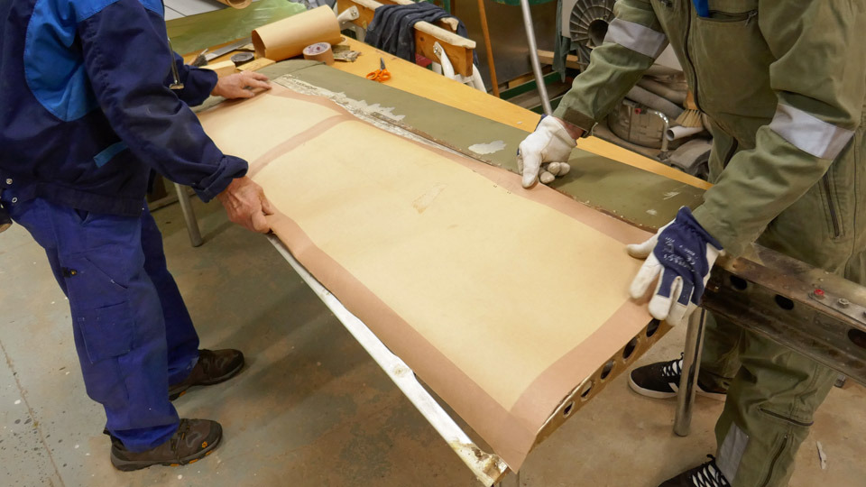
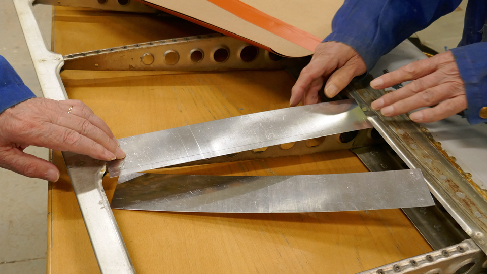
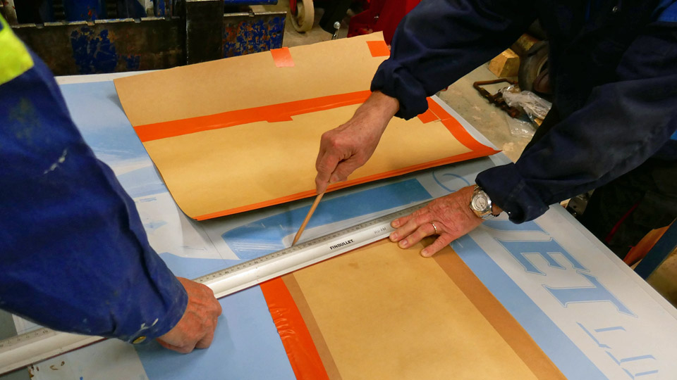
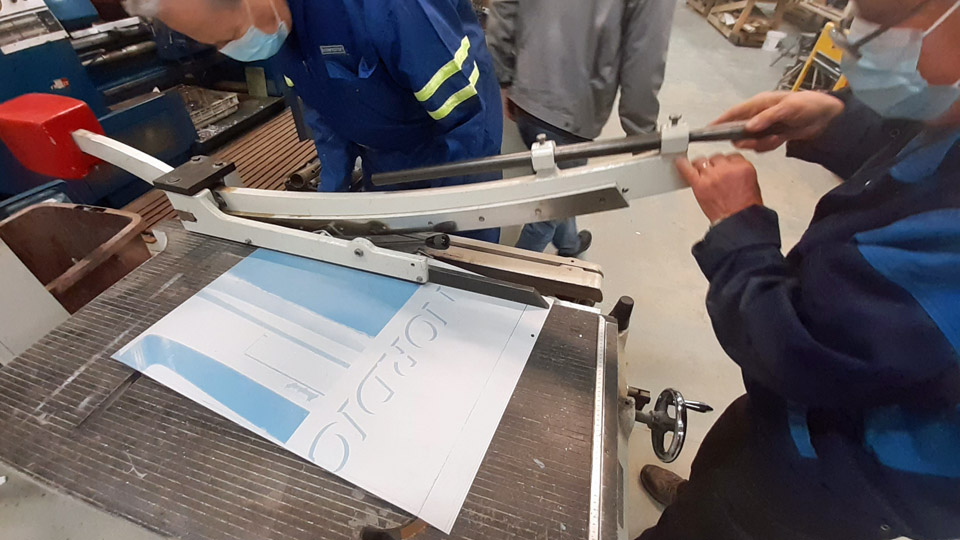
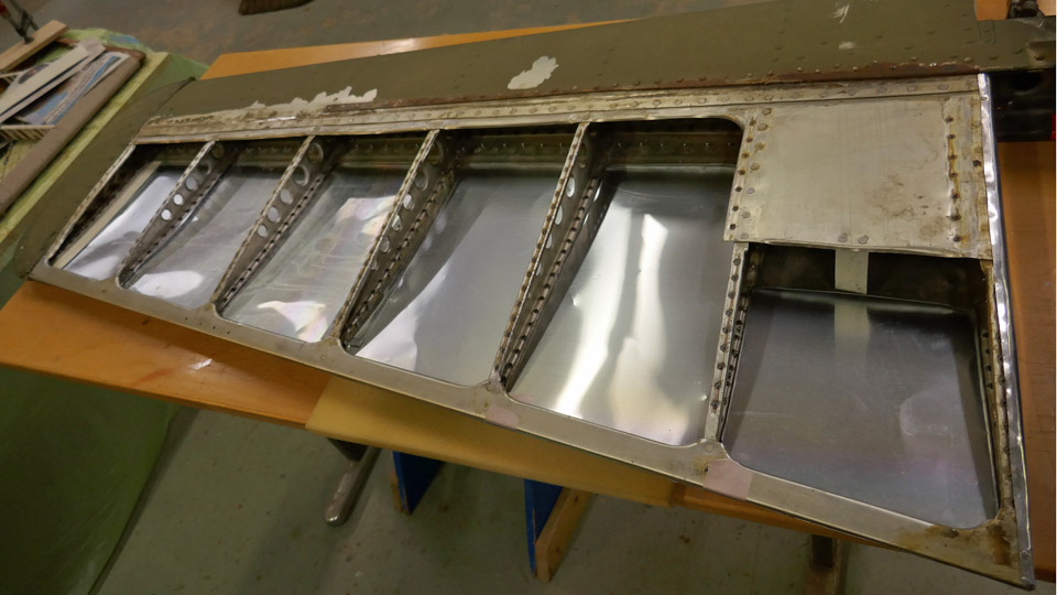
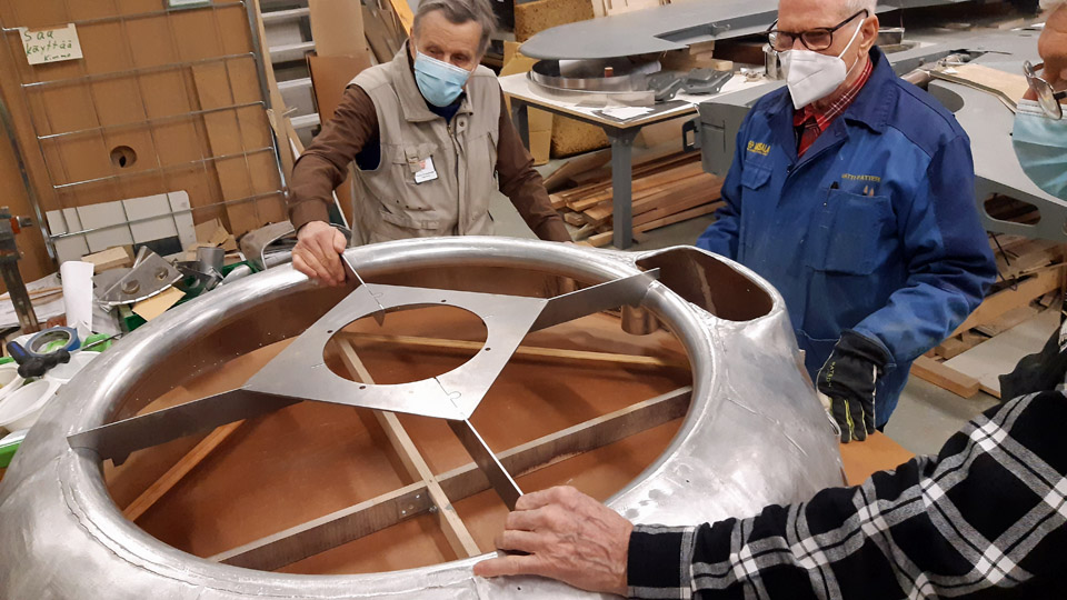
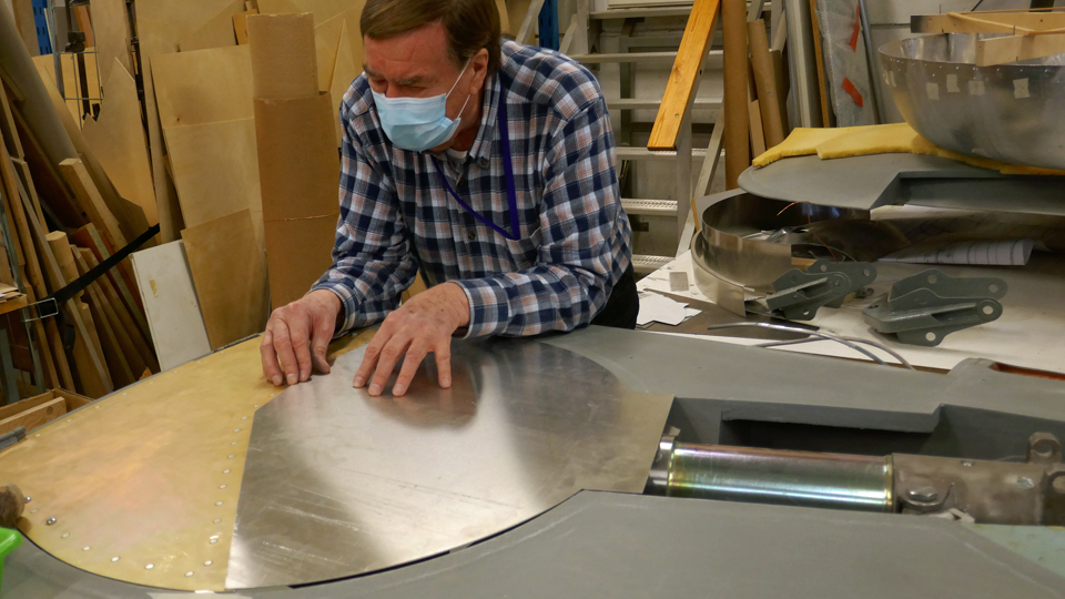
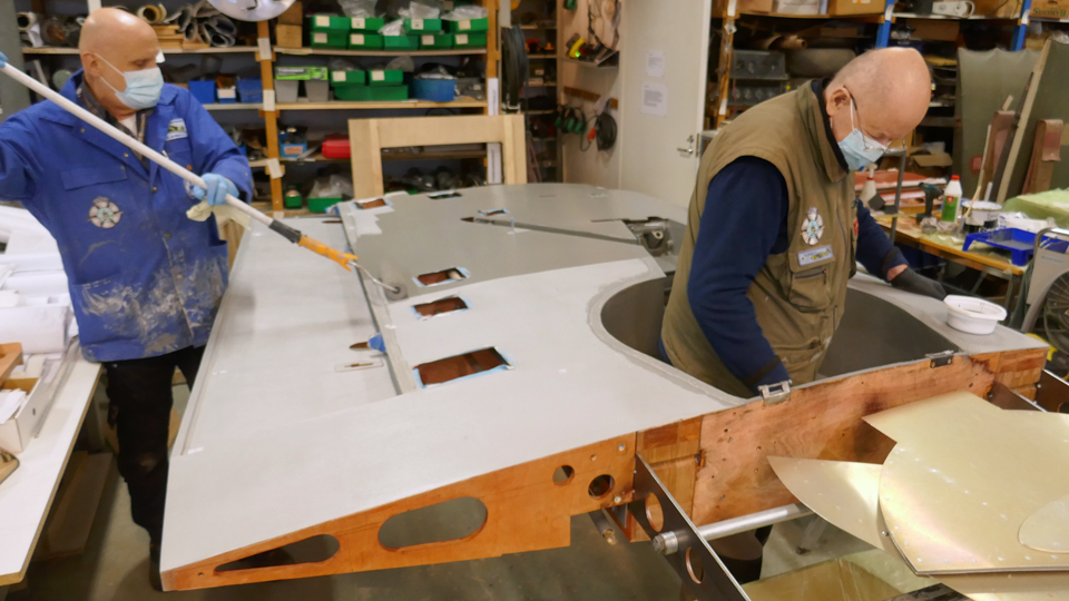
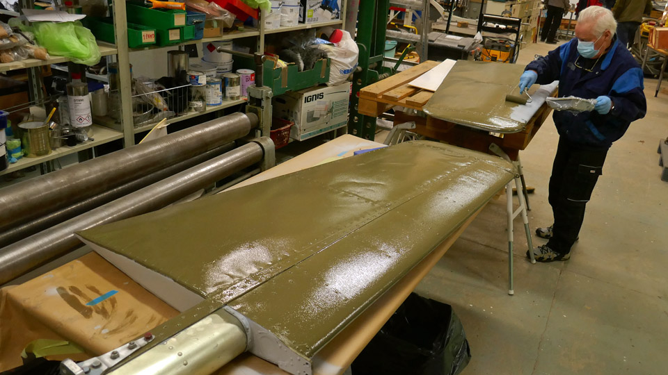
Lower side of Mi-8?s port side tail boom stabilizer has been coveredSunnuntai 17.10.2021 - Tuesday Club member The covering of the Mi-8P helicopter’s tail boom stabilizers is on the way at the Tuesday Club. The helicopter with the identification HS-6 was used by the Finnish Air Force and Army during 1978-2007. The HS-6 would have ended up being scrapped if a place hadn’t been found for it at the Tuulonen shopping centre. The tail boom stabilizers were originally covered with aluminium sheet on the leading-edge side of the spar. On the trailing-edge side the stabilizers are fabric-covered. The HS-6 has been stored outdoors for almost fifteen years and the fabric covering on the tail boom stabilizers has decayed and needs to be replaced. The rotten fabrics have been removed at the Tuesday Club and the work on the new covering has been started. The new covering will be made of aluminium sheet, not fabric, as the leading edge already has. The reason for this is that the HS-6 will be on display outdoors also in the future, so using a more weather-resistant material for covering the stabilizers is preferred. This is a good reason, especially as the aircraft is not a museum item. When repairing and restoring a museum item, the aim is to use original materials and work methods. The covering material is 0.30 mm thick, used offset plates, made of aluminium. They are excellent for this purpose, with good workability. They are printing plates, so they already have an adhesive surface for the future painting work.
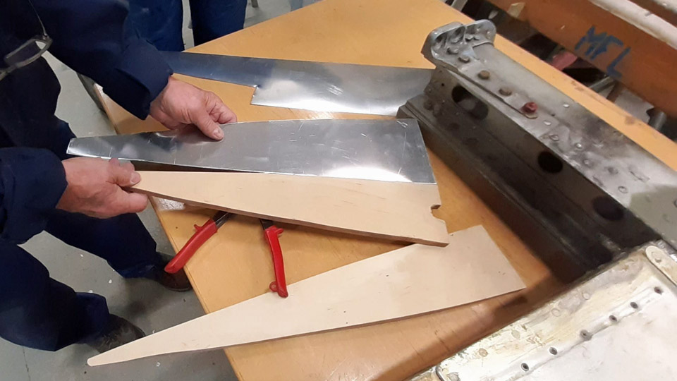
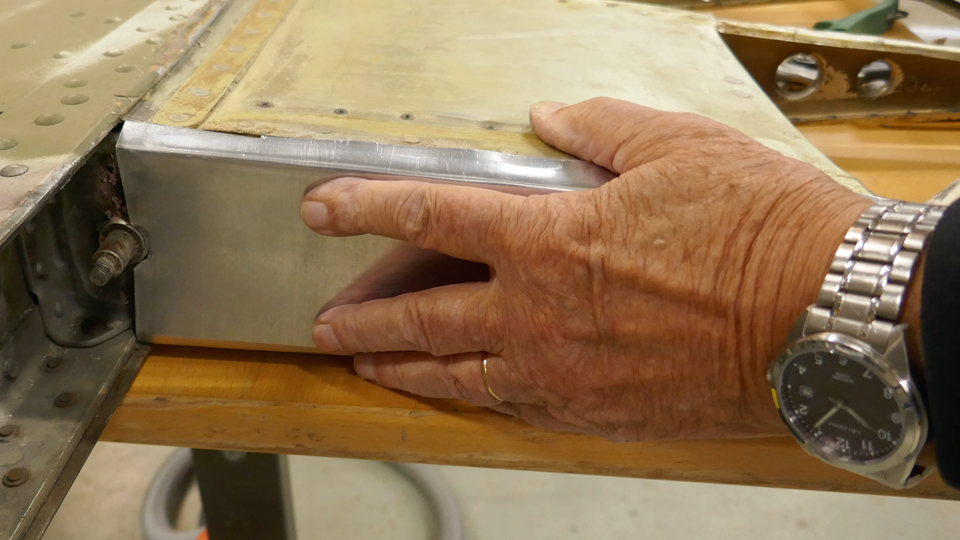
The first surface to be covered with the sheet metal was the tail boom’s port side stabilizer’s lower surface. First the root end of the stabilizer was covered. Its fabric covering had been removed and a piece matching the shape of the fabric was cut from the aluminium sheet. The cutting was done so that the piece of aluminium was about 10 mm larger at its edges than the piece of fabric. This was necessary because the edges of the sheet will be bent over the butt rib’s lower and upper edges. Eventually the bent edges will be covered by the metal sheets, which cover the upper and lower surfaces of the stabilizer and are riveted on the butt rib.
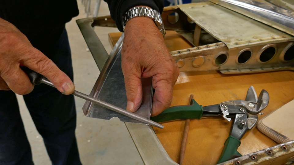
A mould was made from plywood for bending the root sheet edges. The mould is triangular and matches the size of the removed piece of fabric. After the edges of the sheet had been bent, the finalizing work was done with a file. When the root sheet was ready, it was riveted on the butt rib with a couple of flathead rivets.
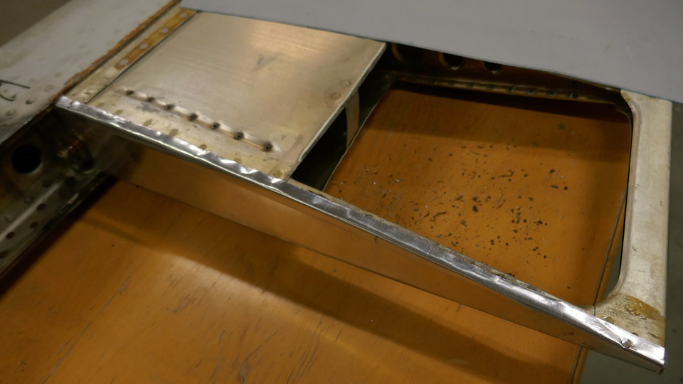
The next step was to make a cardboard model of the stabilizer’s surface which was to be covered. The Tuesday Club team realized that the aluminium offset plates were not large enough for cutting one single sheet which would cover the whole surface which needed to be covered. The upper and lower side of the stabilizer will both have to be covered with two aluminium sheets, which are joined together with a butt joint. The joint will be on top of the rib located in the middle of the stabilizer. An aluminium plate 5 cm wide was riveted on top of this rib to form a base for the butt joint.
The cardboard model was used when the new covering sheet for the stabilizer’s root section was drawn on the aluminium sheet. The covering sheet for the stabilizer’s tip section was drawn on another aluminium sheet. Then the sheets were cut and fitted on the stabilizer. It was noticed that both covering sheets were slightly too wide and a strip a couple of millimetres wide had to be cut from their trailing edge. Now the sheet edges were exactly on the level of the trailing edge.
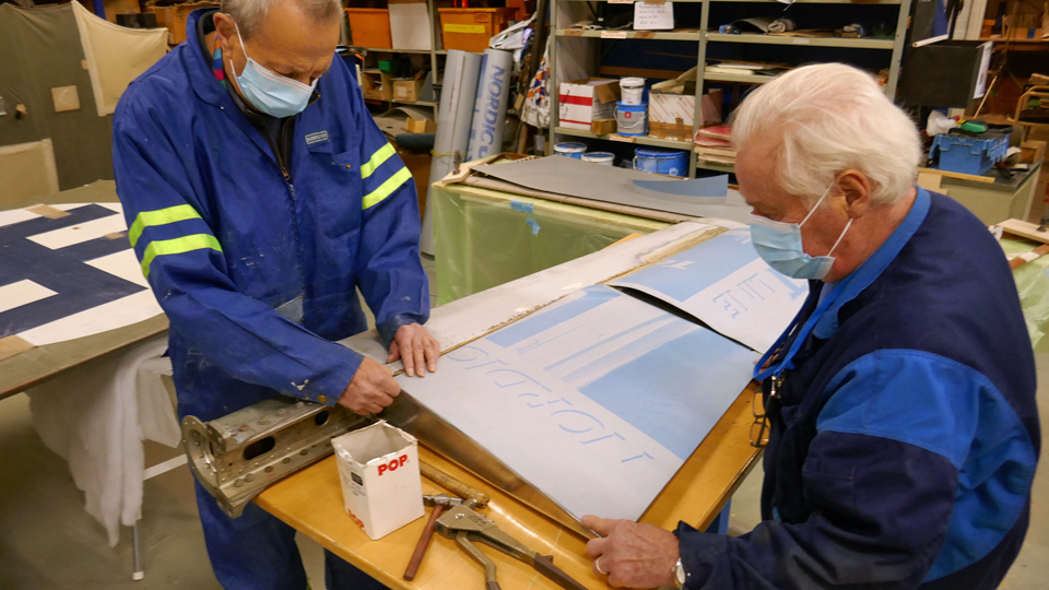
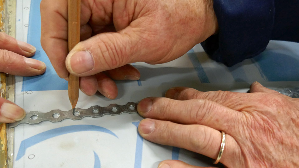
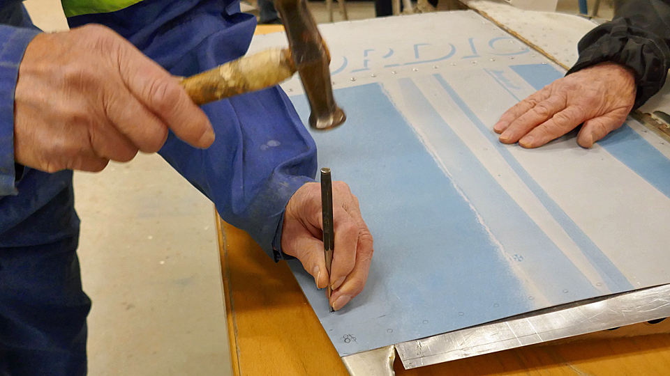
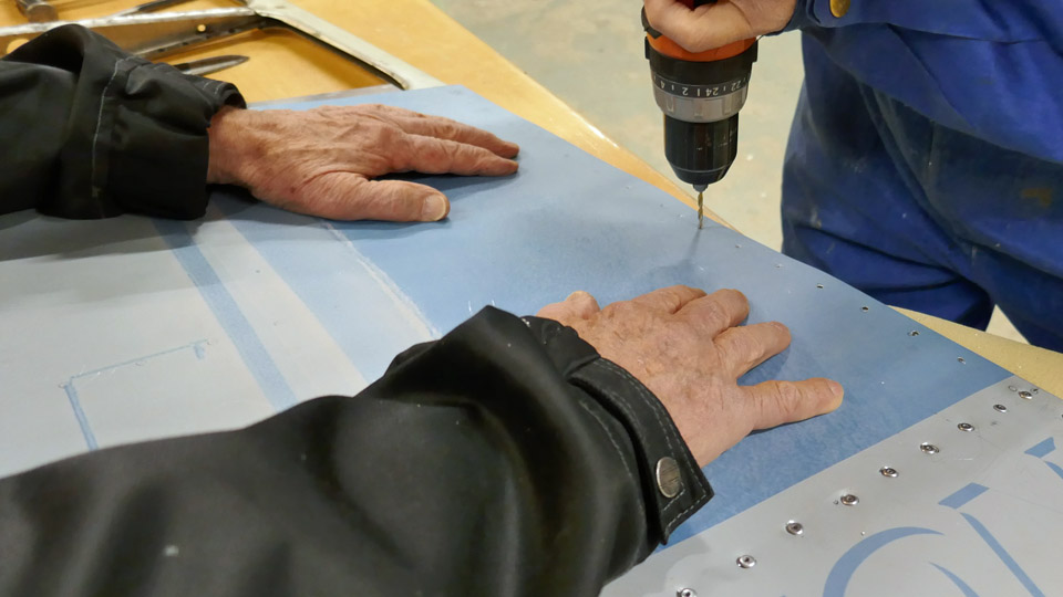
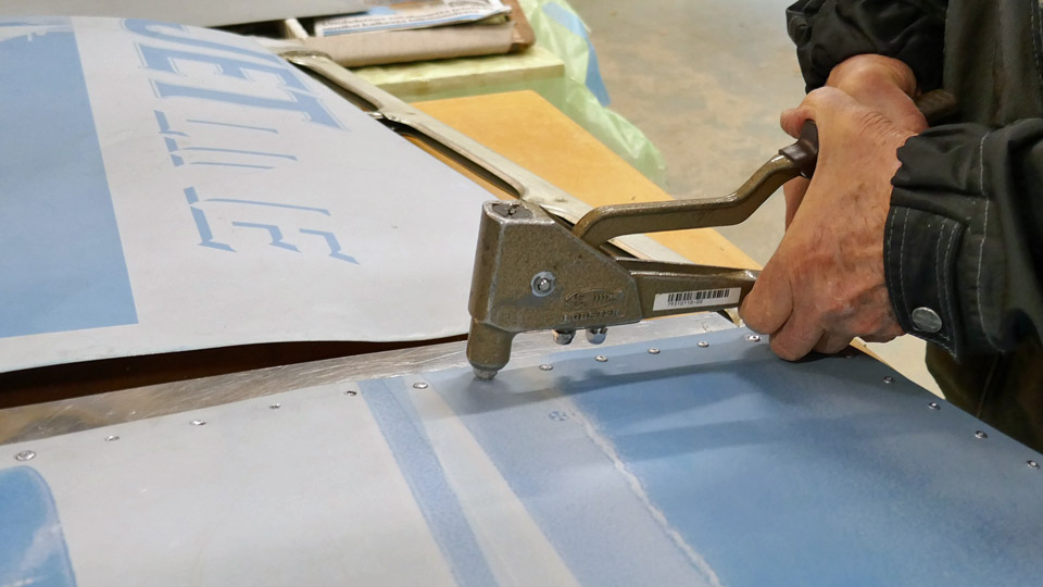
The covering sheets were riveted on the stabilizer and this work was started on the root section. The covering sheet was placed on the stabilizer ribs and locating holes were drilled into its corners. Locating pins were placed in the holes to keep the sheet in place during the riveting work. The following phase of work was to mark the places for the rivets on each rib and on the trailing edge batten. For the marking a perforated galvanised steel fixing strap was used (i.e. a strap for supporting ventilation ducts). This is a good method for marking the rivet holes nicely at even distances. Then a metal point and a hammer were used for making a starting point for drilling at each rivet location. Then the rivet holes were drilled.
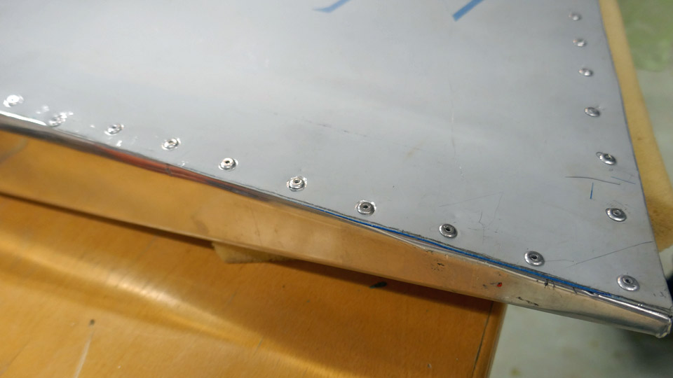
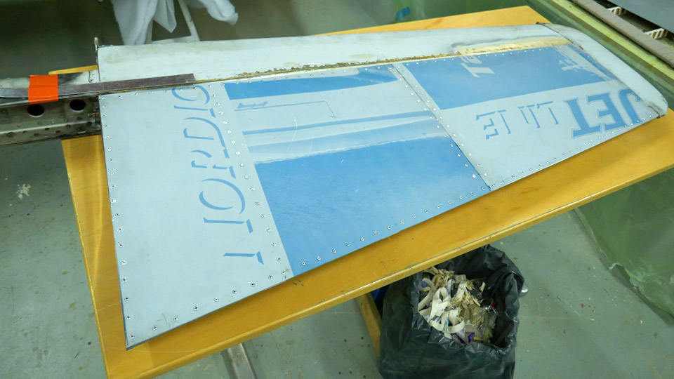
Pop rivets were used when riveting the aluminium sheets into place. The pop rivet was pushed into the drilled hole and squeezed tight using a pop rivet hand tool. When the aluminium sheet on the tail boom port side stabilizer’s lower side root section had been riveted, the same procedure was used when riveting the sheet on the tip section. The lower side of the tail boom port stabilizer has now been covered and the next phase will be the covering of the stabilizer’s upper side. Photos: Lassi Karivalo Translation: Erja Reinikainen |
|
Avainsanat: aviation history, restoration, Mil Mi-8P, HS-6 |

Ilmailumuseot.fi - Aviationmuseums.fi

 Photos: Reino Myllymäki