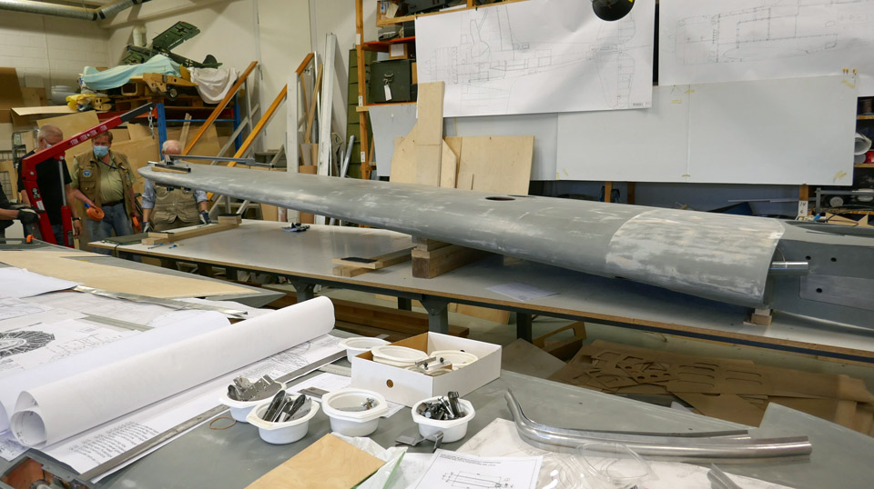
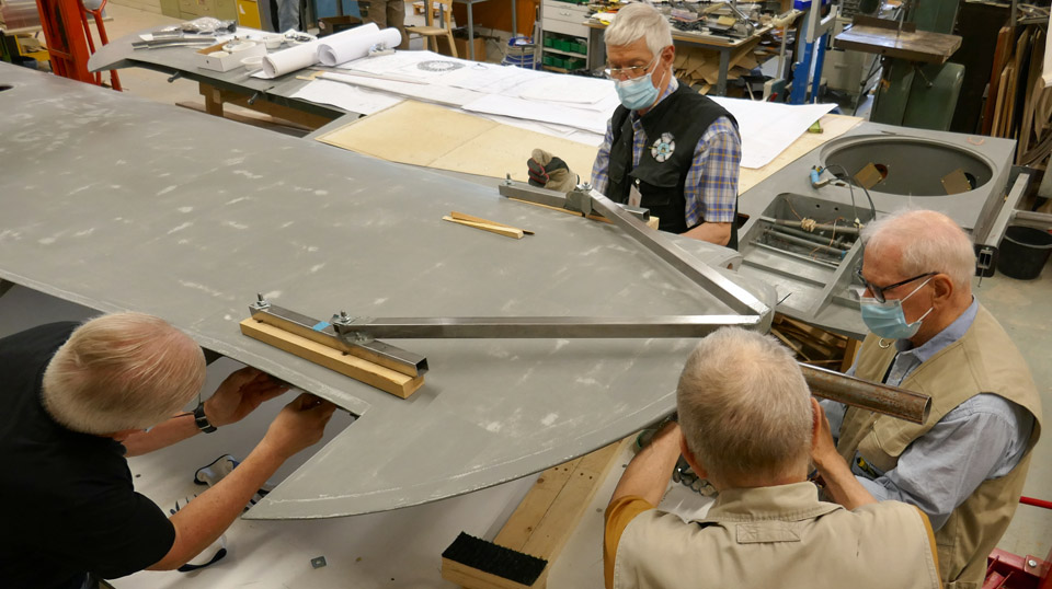
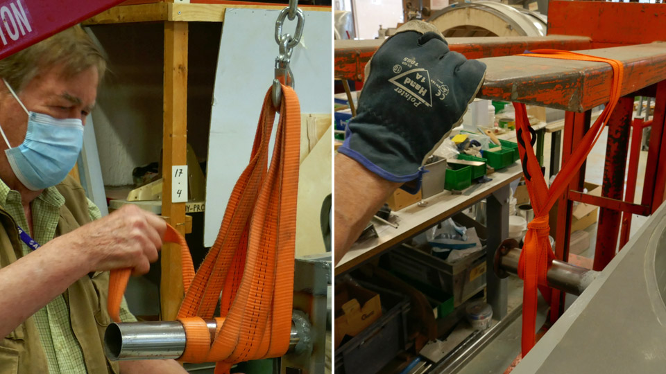
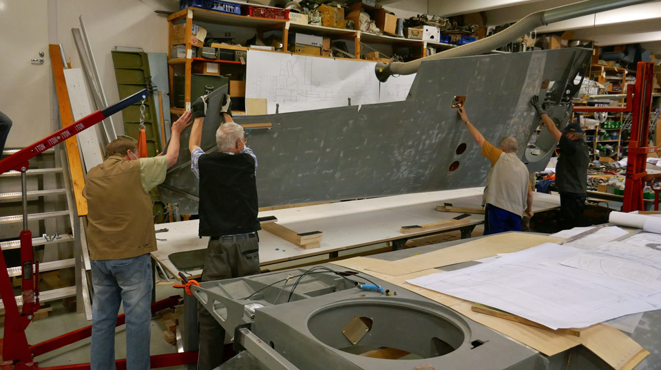
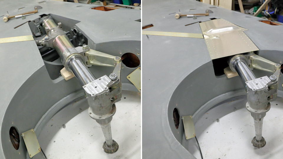
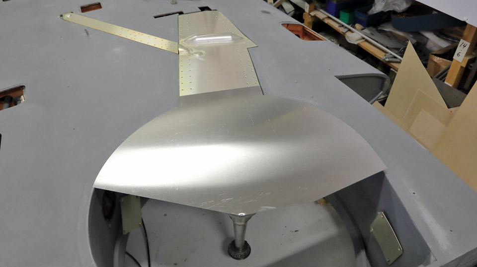
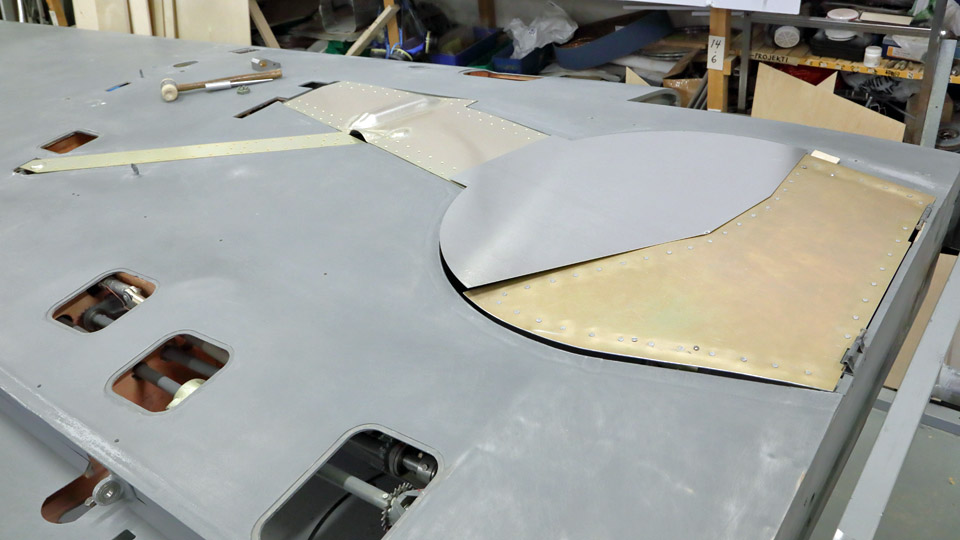
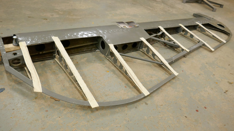
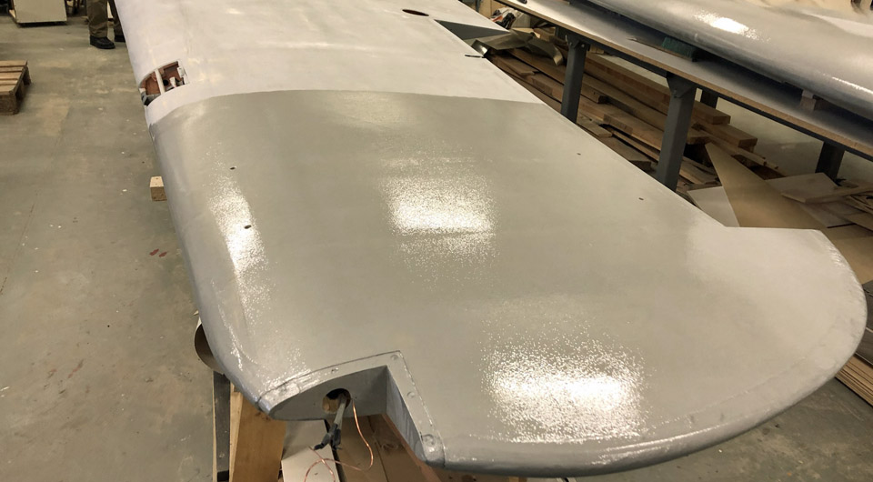
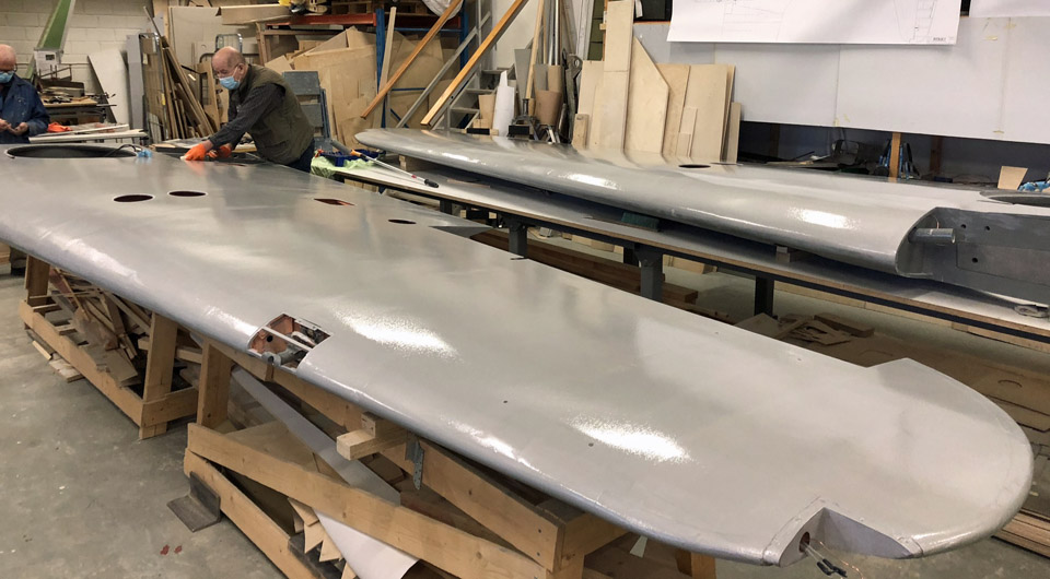
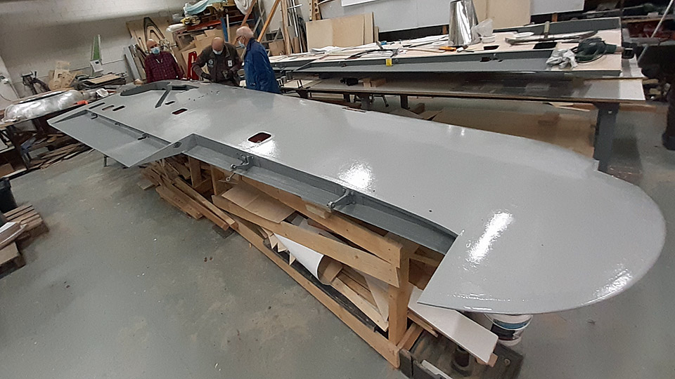
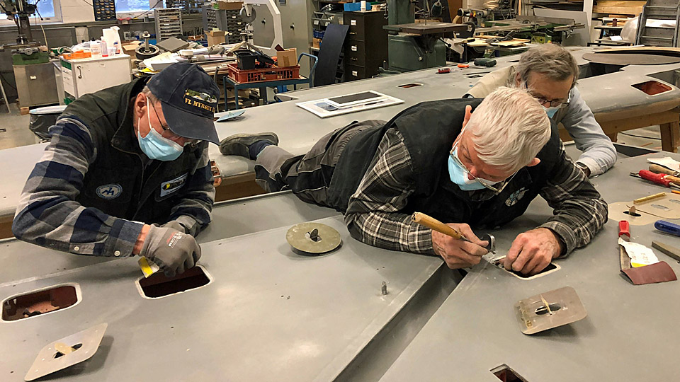
Other work than restorationKeskiviikko 6.10.2021 - Tuesday Club member The Tuesday Club does not only do aircraft restoration projects - the team carries out also other assignments, which are connected to the activities of the Finnish Aviation Museum and the Aviation Museum Society.
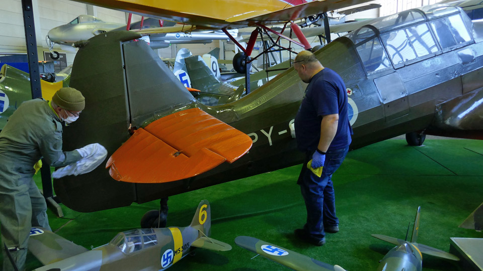
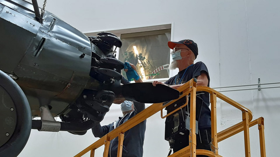
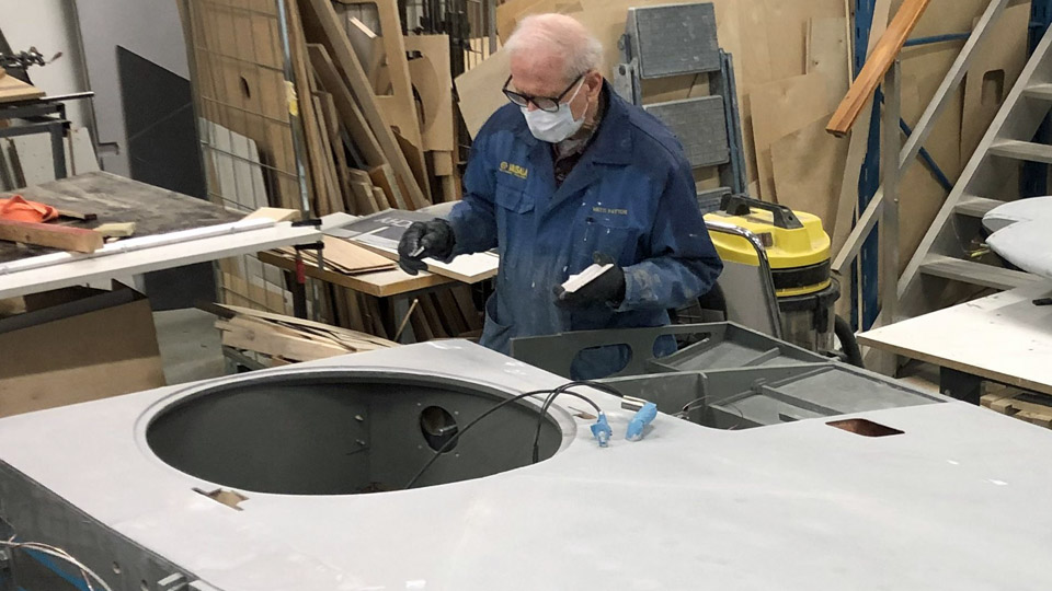
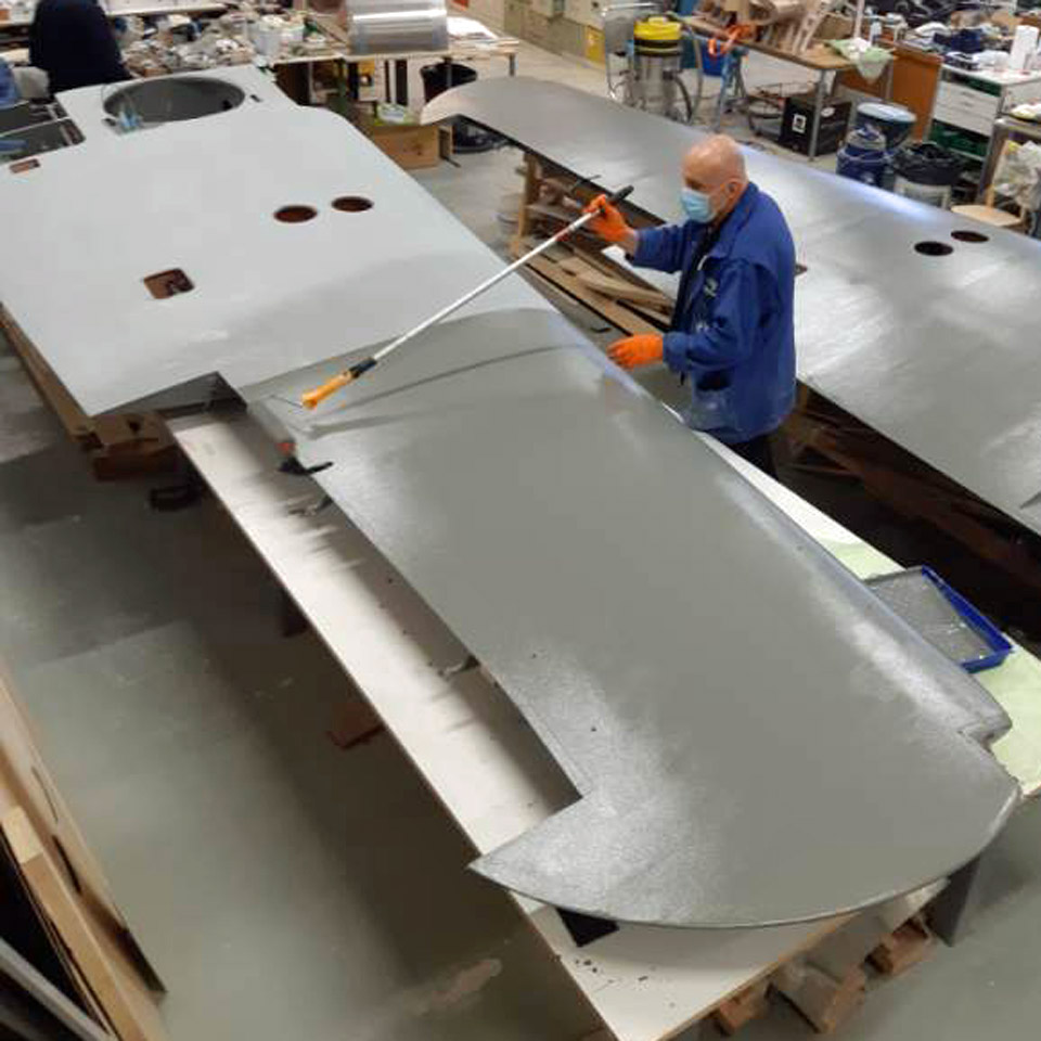
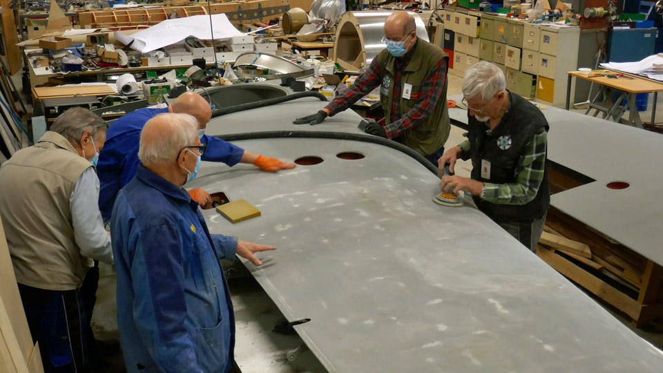
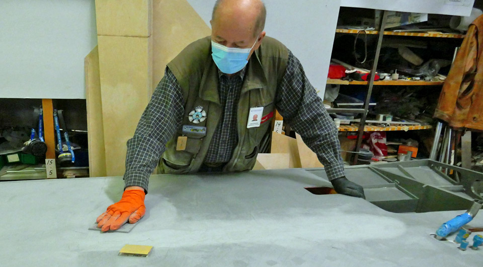
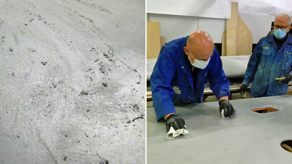
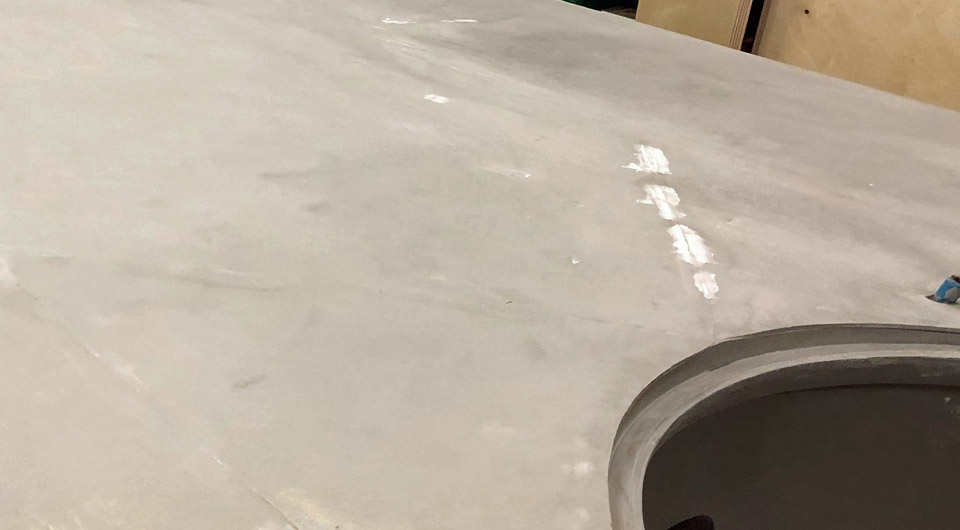
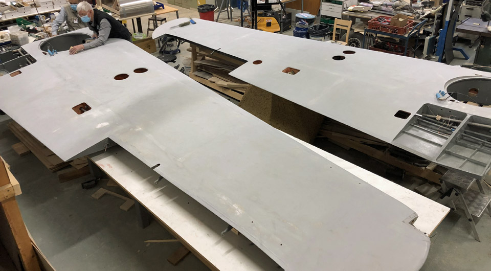
During the autumn the dust removing work has been started in the Finnish Aviation Museum’s Hall I and Hall II. A major dusting the museum aircraft surfaces was done about three years ago. Now mainly the surfaces of the aircraft on the museum floor are cleaned, because the dusting of the aircraft hanging from the ceiling requires a lifting platform, which isn’t available at the moment. The surfaces of the aircraft in Hall I are already bright and clean for the visitors to admire.
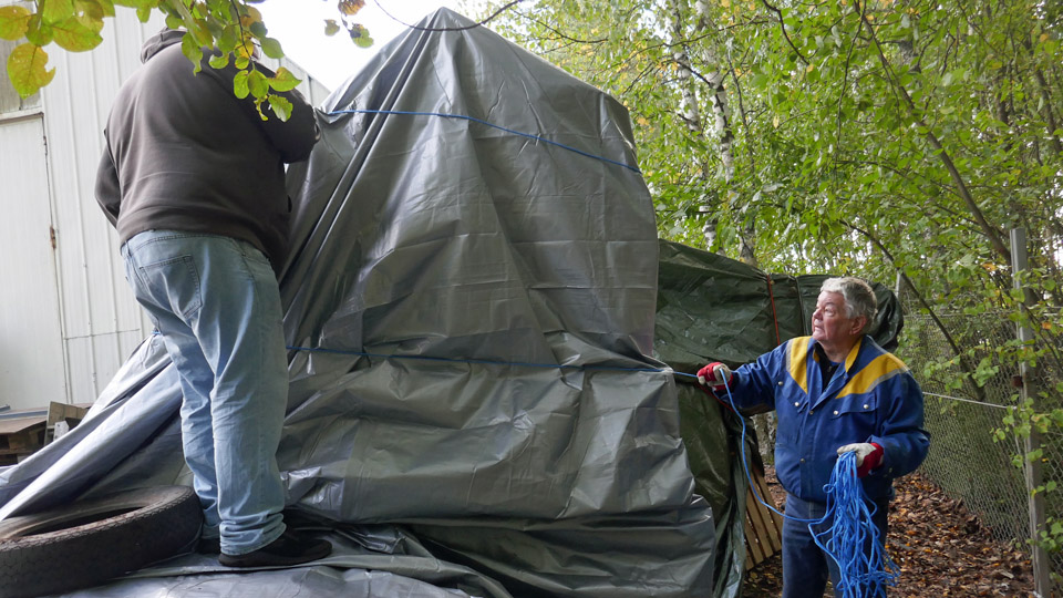
There are some aircraft fuselage frames and rear fuselages stored on the yard of the Aviation Museum. These include the rear fuselages of Bristol Blenheim (BL-180) and Douglas DC-3 (OH-LCA). Of the Blenheims which were in use in Finland, the BL-180 belongs to the series V. The OH-LCA was destroyed in 1963 when it hit the trees when landing on the Maarianhamina airfield. During the years the tarpaulins which have covered the rear fuselages have ripped and decayed and they were renewed. The DC-3 tarpaulin was replaced already earlier this year. The Tuesday Club team helped the museum staff to remove the torn tarpaulin from the BL-180 fuselage and covered it with a new one.
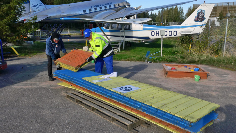
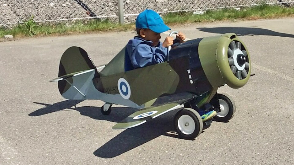
During the summer there is a fenced Children’s World outside the Finnish Aviation Museum. There young visitors can drive around on the pedal aircraft, made by the Tuesday Club, or “fly” in the real Cessna 172 Skyhawk (OH-COO), which was purchased for this purpose. In the autumn the Children’s World was closed and prepared for the winter. The Tuesday Club team helped the museum staff to take down the surrounding fence and to move the Cessna under the wing of the neighbouring DC-3 “Lokki” (OH-LCD) for the winter.
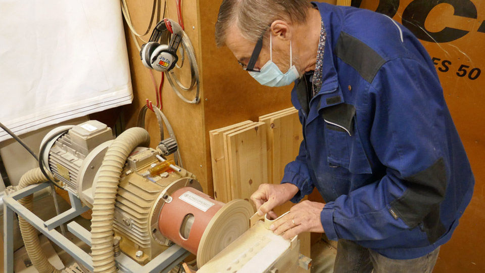
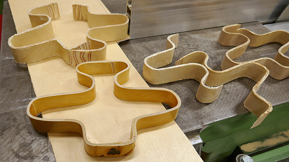
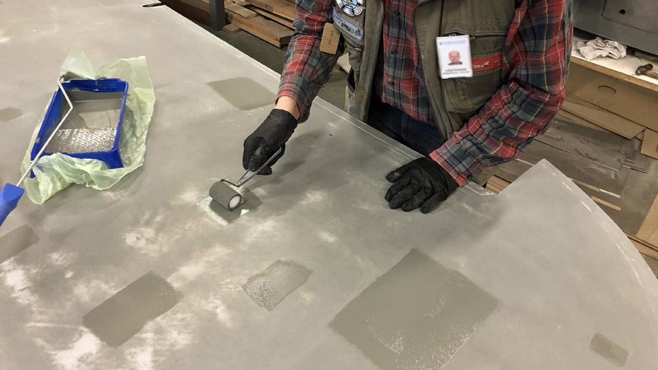
The Tuesday Club team has made aircraft-shaped pot coasters which have been for sale in the Aviation Museum shop as well as in the webshop of the Aviation Museum Society. These popular pot coasters ran out, but more will be made during the autumn.
Photo: Janne Salonen.
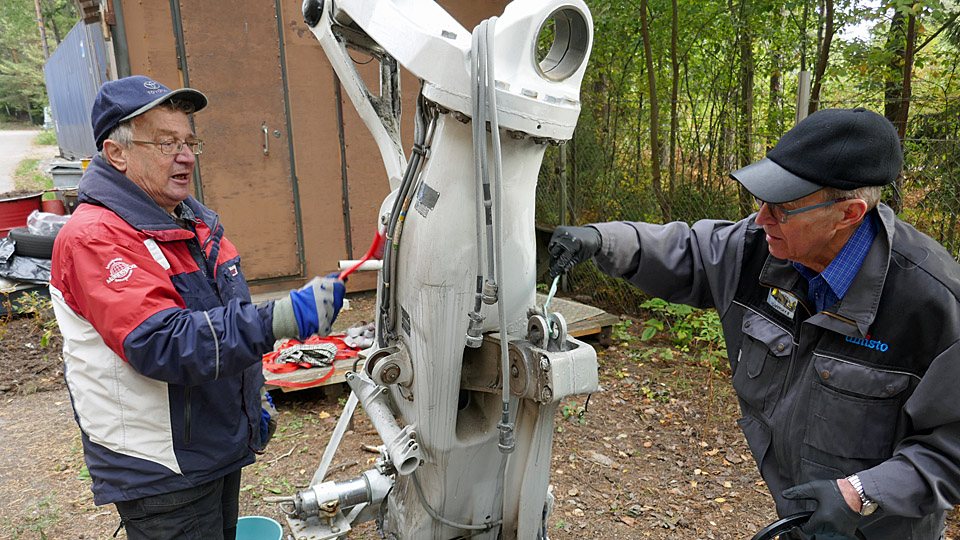
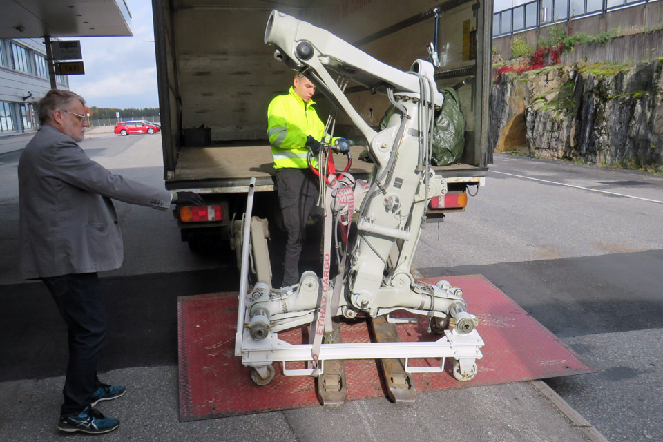
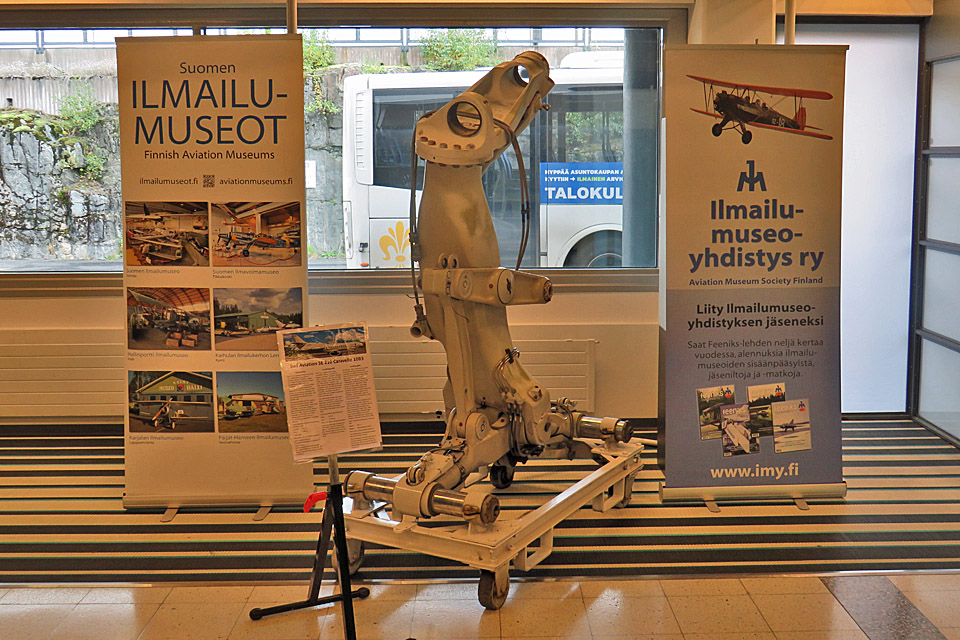
Photo: Janne Salonen. The Aviation Museum Society’s Caravelle-project has now taken a step forward as the airport company Finavia and the Aviation Museum Society have agreed that the Sud Aviation SE 210 Caravelle III, which has been standing in Arlanda in Sweden, will be placed on display at the Turku airport. A taste of Caravelle has already been sent to Turku: the main landing gear of a Super Caravelle. The landing gear is owned by the Aviation Museum Society, and it was cleaned at the Tuesday Club before it was delivered to the Turku airport terminal and placed on display there. Photos: Lassi Karivalo except if separately otherwise mentioned. Translation: Erja Reinikainen. |
|
Avainsanat: aviation history, restoration, Tuesday Club |
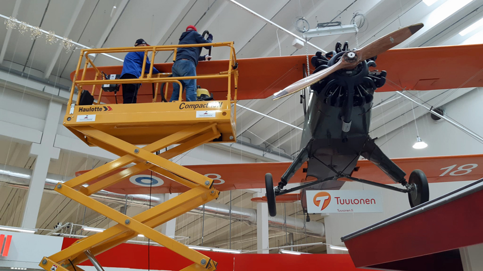
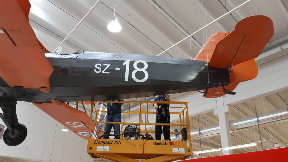
Stieglitz SZ-18 at Tuulonen shopping centre was cleanedMaanantai 4.10.2021 - Tuesday Club member Focke Wulff w 44 Stieglitz (SZ-18), which is owned by the Aviation Museum Society, has been on display for some years at the Tuulonen shopping centre in Hämeenlinna. Earlier the Stieglitz was on display at the Tuurin Kyläkauppa shopping centre. The SZ-18 has been restored by the Tuesday Club.
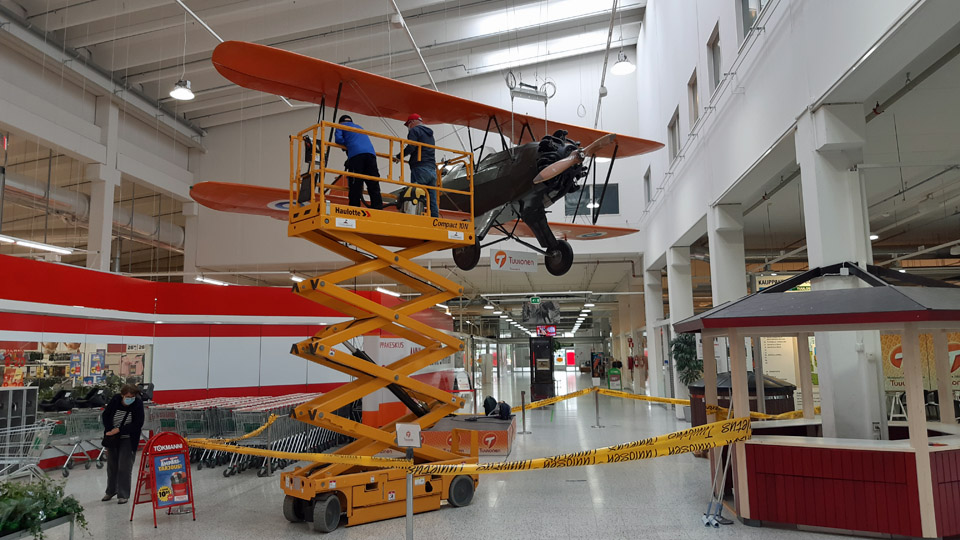
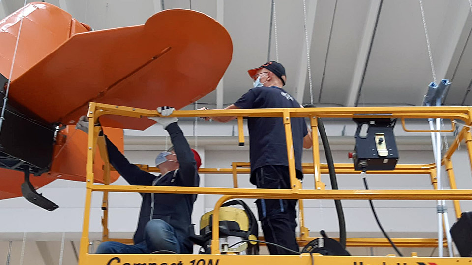
The Stieglitz SZ-18 has already been at the shopping centre a number of years and dust had gathered on its surfaces. It was time to do some cleaning. It was agreed with the shopping centre that two members of the Tuesday Club will come and do the cleaning. The shopping centre will provide the equipment and a scissor lift. The aircraft is hanging from the ceiling of the shopping mall atrium and a scissor lift is needed when the aircraft’s surfaces are cleaned without lowering the aircraft to floor level.
When the Tuesday Club members arrived at Tuulonen on September 15th, everything was ready for the cleaning work: an industrial vacuum cleaner, mops, cleaning cloths and buckets, filled with water. But first some coffee. Then the cleaning team climbed on the scissor lift and the work was started. The shopping centre staff moved the scissor lift under the aircraft during the cleaning.
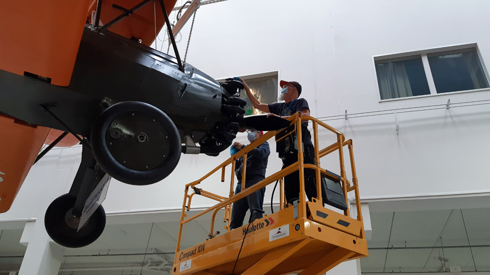
First the heavy layer of dust was vacuumed from the aircraft’s surfaces and then the surfaces were mopped with damp mops and cloths. The shopping centre staff rinsed the dirty mops and cloths in buckets and changed the water in the buckets when the scissor lift was moved. The co-operation worked well, and the cleaning progressed efficiently. The Tuesday Club team commented the good co-operation by saying that “the Tuulonen guys were really nice, and this task leaves a good memory”.
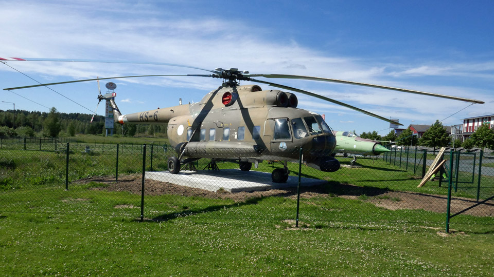
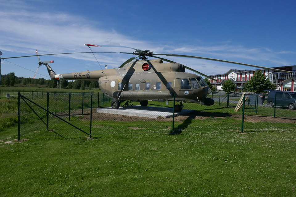
Now the Aviation Museum Society’s Stieglitz is shining bright again and can be admired by the customers of the Tuulonen shopping centre. The customers can also see other aircraft on display at the Tuulonen shopping centre. There is a DC-2 (DO-1) “Hanssin Jukka” in a hangar, and Saab 35FS Draken (DK-247) and Mig 21 BIS (MG-124) fighters and Mil Mi-8P (HS-6) helicopter on the yard. The Tuulonen shopping centre is already a small aviation museum for the aviation history enthusiasts and other customers to enjoy. Photos: Kimmo Salomaa Translation: Erja Reinikainen. |
|
Avainsanat: aviation history, restoration, Focke-Wulf Fw 44 Steglitz, SZ-18 |
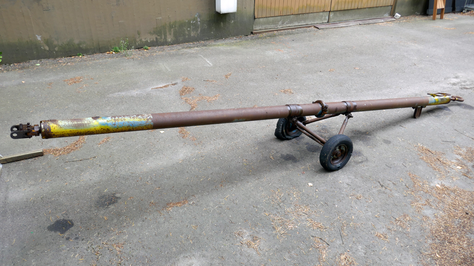
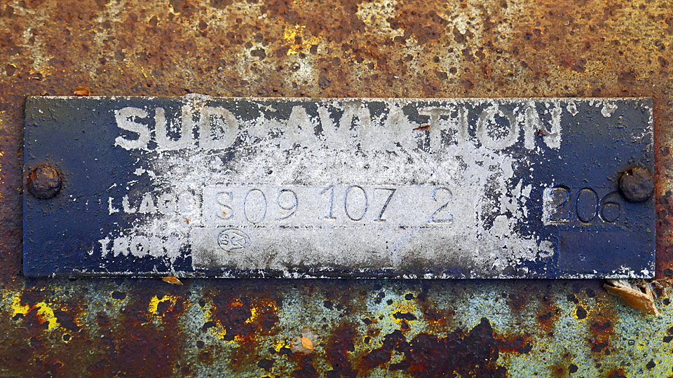
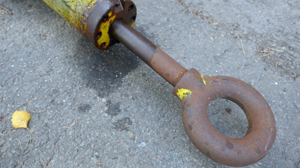
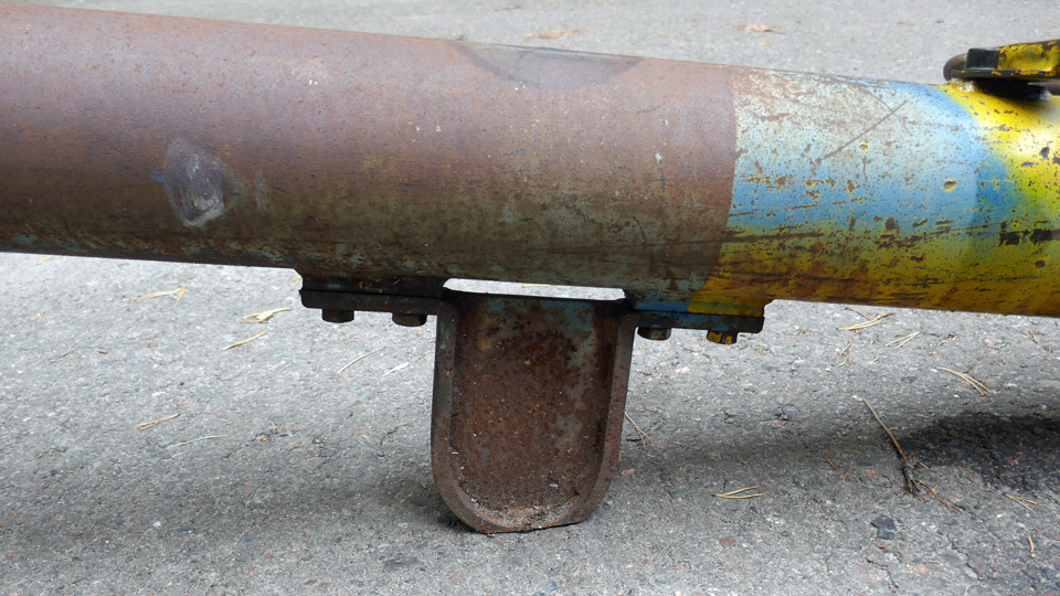
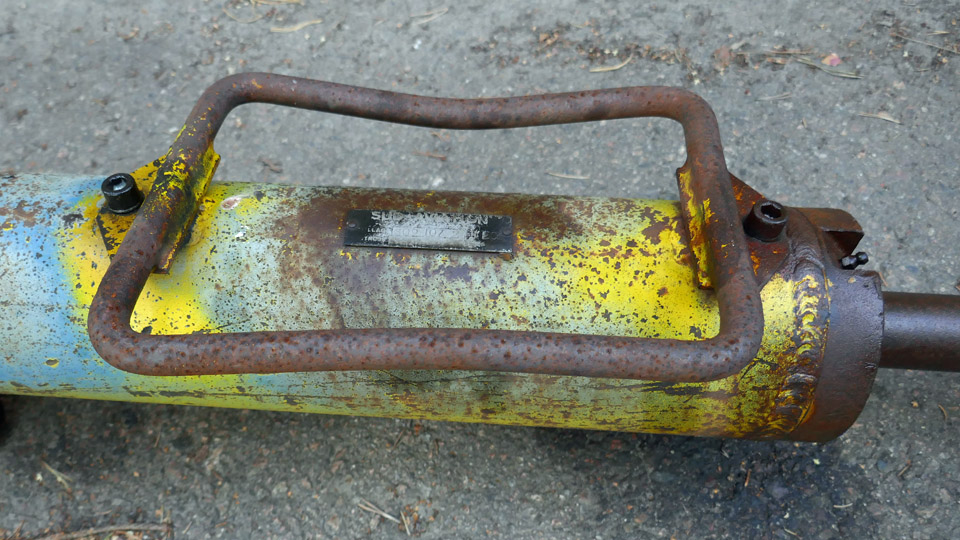
Super Caravelle's towbar is being repaired at Tuesday ClubTorstai 23.9.2021 - Tuesday Club member The Aviation Museum Society has an original towbar for Sud Aviation SE 210 Super Caravelle, which has been used by Finnair, but is now in poor condition. The towbar still has a Sud Aviation manufacturing plate on it. The towbar was donated by Swissport, where it has been stored outdoors since the Caravelles were removed from operation in the 1980s. The towbar will be restored into its original Finnair appearance as a part of the Caravelle-project, which aims to place the Caravelle SE-DAF (Caravelle III version) from Arlanda on display in Finland.
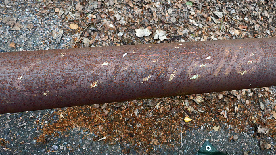
The restoration of the towbar will involve a lot of work: the five-meter-long towbar is covered in a heavy layer of rust, due to the long storage outdoors. The original layers of paint have almost completely been destroyed by rust.
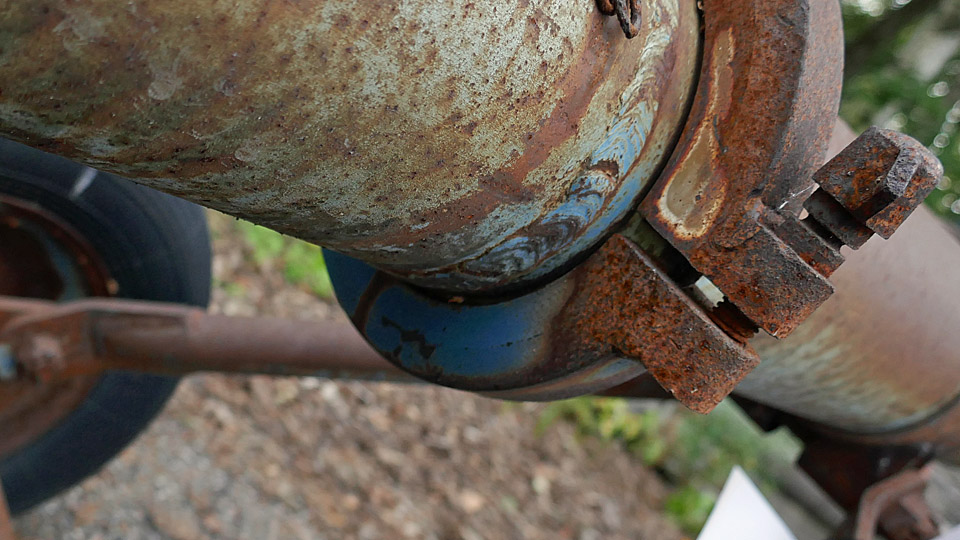
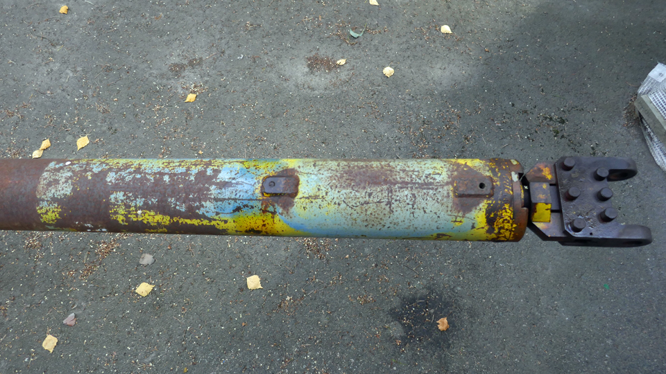
The towbar has been painted light blue with bright yellow signal colour at both ends. Fortunately there is some original blue paint visible on the lower side of the towbar and under the brackets and some yellow at the ends. In the middle there is the text Super Caravelle, painted in white and barely visible.
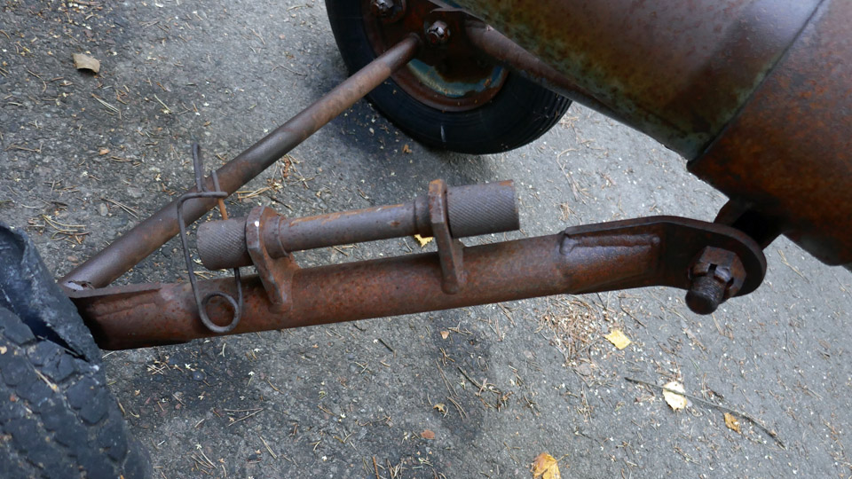
At the tow-vehicle end of the towbar there is a shaft with a spring, which is pushed into the towbar. The spring of the shaft is located inside the towbar. There is a pull-eyelet at the end of the shaft to fasten the towbar on the hook of the pulling or pushing vehicle. The shaft has rusted and doesn’t move. The aim is to restore it into an operating condition.
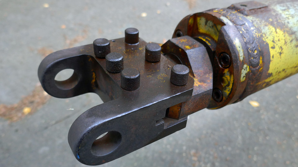
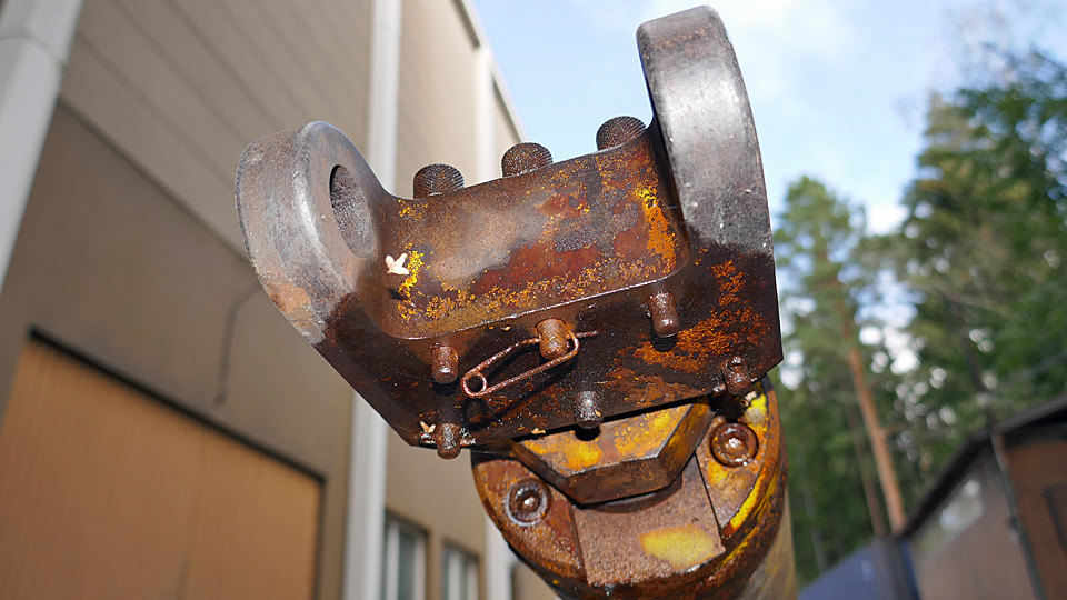
At the other end of the towbar there is a tow-fitting for fastening the landing gear heads, which are aircraft type specific. The Caravelle nose landing gear head is fork-shaped and has six metal pins to lock it on the tow-fitting. The pins are secured with fokker pins at their lower end. The towbar is fastened on adapter on the aircraft’s nose wheel with the landing gear head, which has a shear pin. The tow-fitting, the landing gear head, and the shear pin will be restored into operating condition.
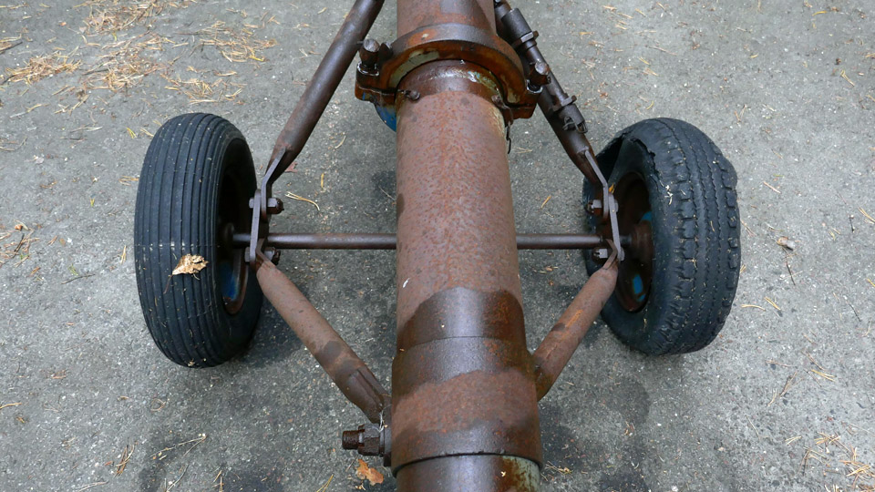
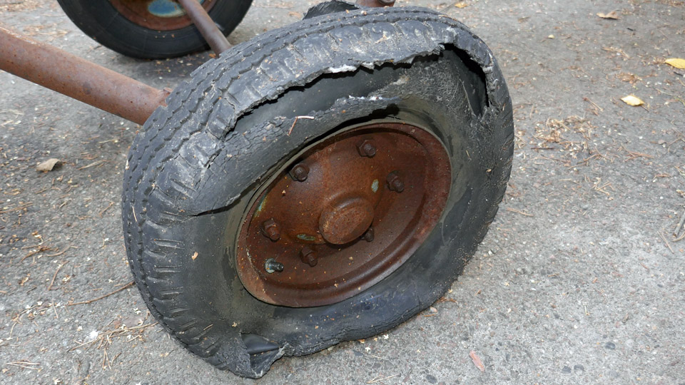
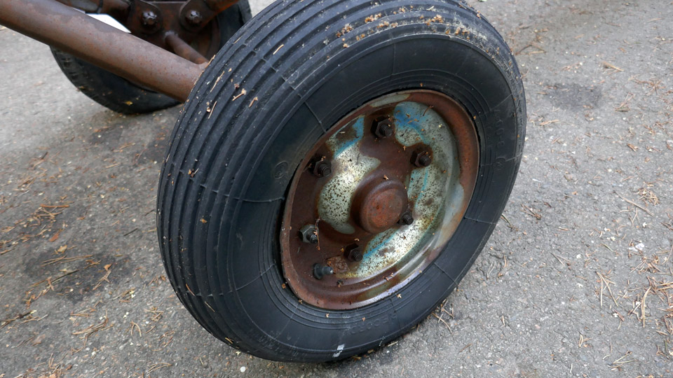
In the middle of the towbar there is a pair of wheels for moving the towbar. The wheels are located slightly off the towbar’s longitudinal centre of mass. Therefore the end with the pull-eyelet tilts towards the ground. Under the towbar there is a metal leg which balances the towbar and prevents the pull-eyelet from touching the ground. The shear pin of the towbar is kept on the wheel arm, which has brackets with holes for holding the shear pin.
The wheel rims and the wheel arms have rusted, and they will be cleaned and painted. The outer tyre on the starboard side has broken and so has probably also the inner tyre. New outer and inner tyres will be installed. The outer tyre on the port side is still intact and in good condition. There is still air inside the tyre, it is probably “old air” from the 1980s.
At both ends of the towbar there is a rectangular metal hoop. These hoops were used when the towbar was moved, or its end was lifted when it was fastened on the pushing/pulling vehicle or on the aircraft’s nose wheel. One of the hoops has disappeared but its holder holes can be seen on the towbar surface. A new lifting hoop will be made. The restoration of the Caravelle towbar will begin by dismantling it into pieces as far as possible. That won’t be easy because the towbar and its parts with their fastening bolts and nuts have rusted badly. For disassembling the parts rust removing chemical has been applied. If necessary, the parts will be disassembled by heating. The larger rusted parts of the towbar will be cleaned by sandblasting, this will be done by a contractor. The smaller parts, such as bolts, pins, locking pins and nuts can be sandblasted using the sandblaster at the Finnish Aviation Museum. When all the parts of the towbar have been cleaned from rust, the parts will be painted with undercoat paint which will prevent rusting. On top of that a finishing layer of light blue and bright yellow paint will be applied. Before sandblasting the hue of the blue and the yellow will be defined from the original painted surfaces which are still visible. The text Super Caravelle in the middle of the towbar has almost faded away, but it can still be copied on transparent paper or plastic. The text will be repainted on the restored towbar. Photos: Lassi Karivalo Translation: Erja Reinikainen. |
|
Avainsanat: aviation history, restoration, Caravelle |
Tail boom stabilizers of Mil Mi-8P (HS-6) are being coveredTiistai 14.9.2021 - Tuesday Club member The tail boom stabilizers of the Mil Mi-8P (HS-6) helicopter, which is on display on the yard of the Tuulonen shopping centre, have been brought to the Tuesday Club to be repaired. The HS-6 helicopter was on display outside the Finnish Aviation Museum for a long time then, some years ago, it was moved to Vesivehmaa, to stand in front of the Päijät-Häme aviation museum hall. The helicopter was approaching scrapping, but fortunately a place was found for it at the Tuulonen shopping centre. The shopping centre has quite a remarkable collection of different aircraft on display: Saab 35FS Draken (DK-247) and MiG 21 BIS (MG-124) fighter jets on the yard and Douglas DC-2 (DO-1) “Hanssin Jukka” and Focke Wulf Fw 44 Stieglitz (SZ-18) indoors. The shopping centre can already be called a small aviation museum.
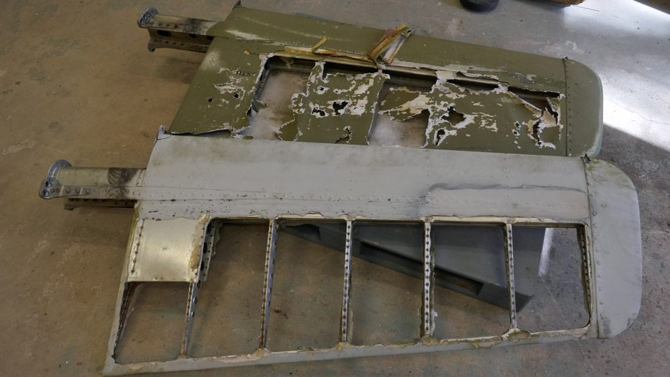
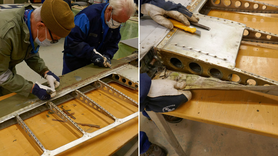
The tail boom stabilizers of HS-6 consist of an aluminium frame and are half covered with fabric. The fabric covers the area between the stabilizer’s trailing edge and the spar, about half of the stabilizer’s area. The fabric areas have been badly damaged because the HS-6 has been standing outside since the Defence Forces removed it from service in 2007.
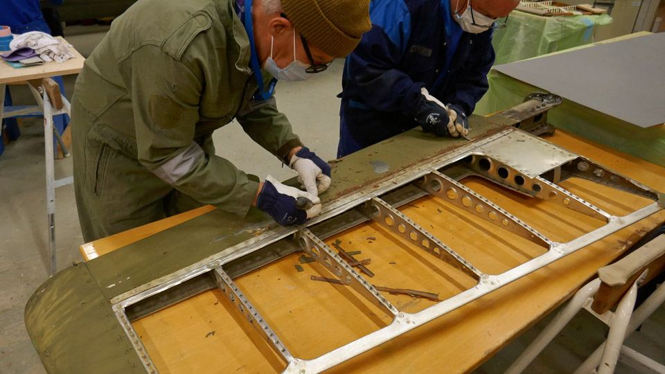
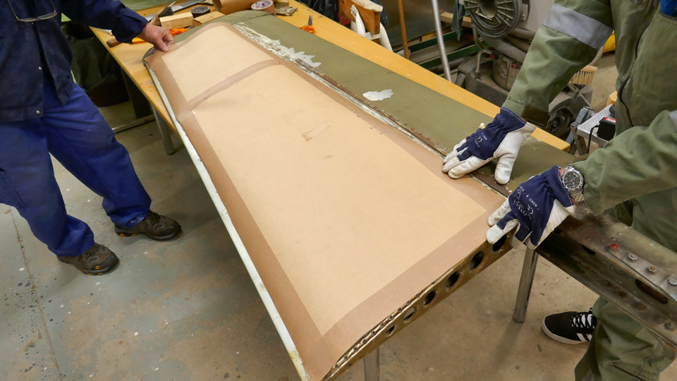
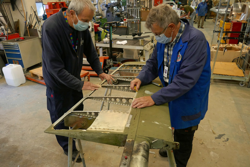
The task of the Tuesday Club team is to remove the decayed fabric covering and to replace it with a thin sheet of aluminium. The Mi-8 can’t be considered an actual museal artefact anymore and the fabric covering would rot again as the helicopter is permanently on display outside the Tuulonen shopping centre.
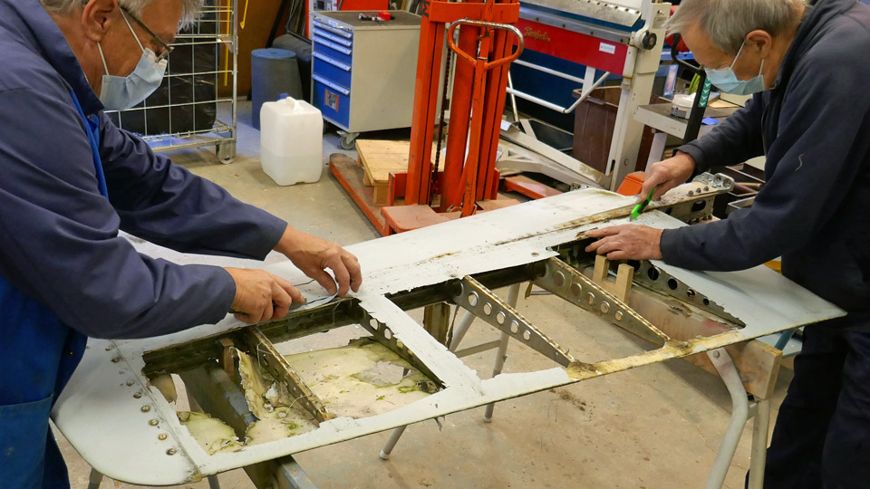
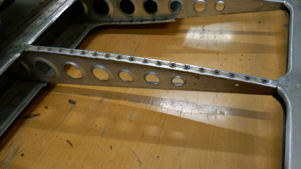
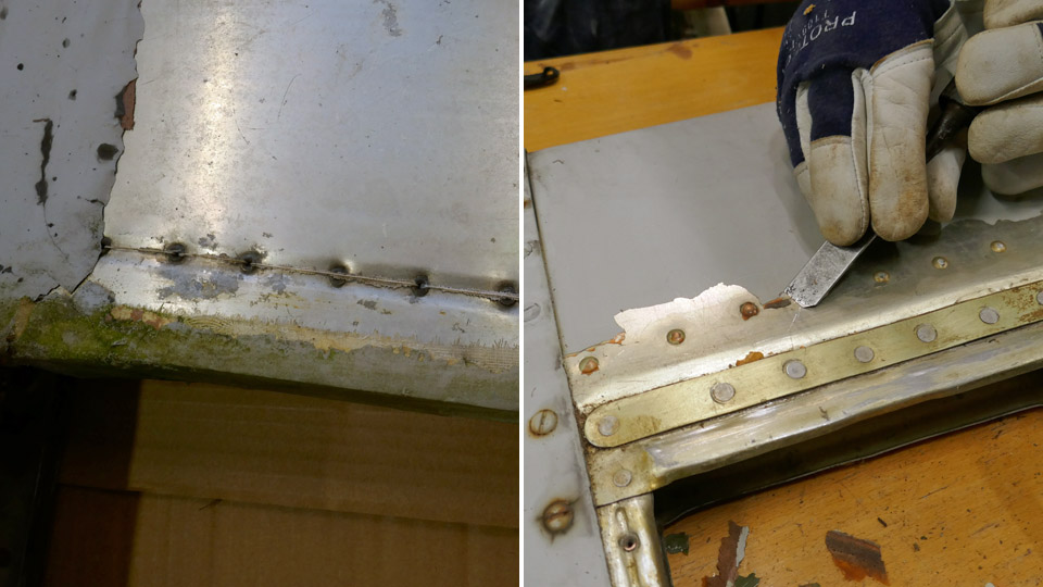
The work was started by removing the rotten fabric from the stabilizer. The aluminium ribs and other surfaces, which had now been revealed, were cleaned. The stiffening steel batten, running parallel to the stabilizer’s spar, had rusted and it was cleaned. The paint on the stabilizer’s aluminium surface had partly flaked off. The flaked paint was removed, and the surface was cleaned to clear aluminium.
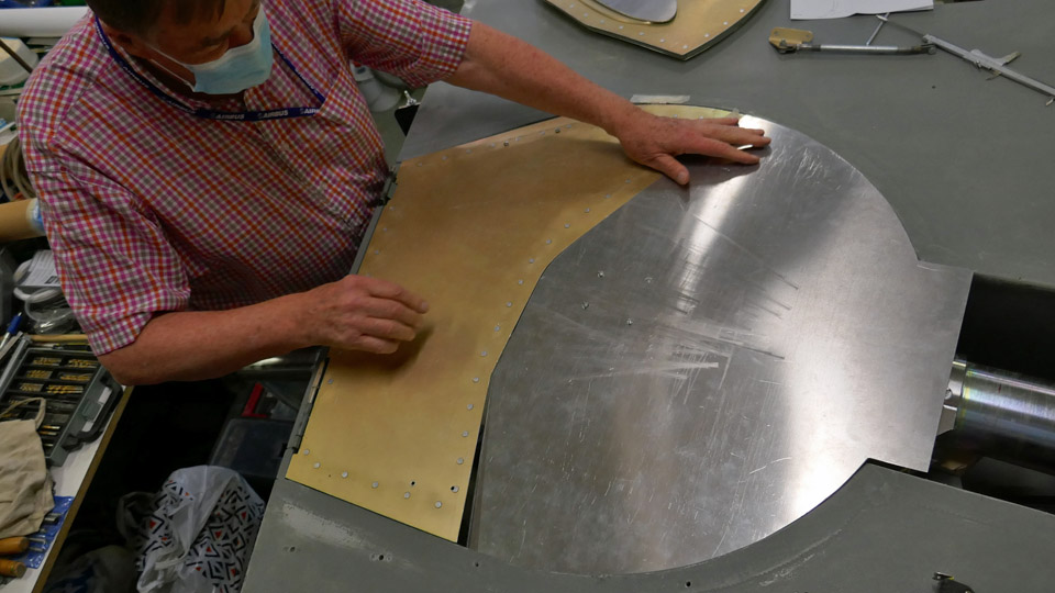
A cardboard model was made of the stabilizer’s surface which will be covered with a sheet of aluminium. The covering sheets will be cut from aluminium plate according to the cardboard model and riveted on the upper and lower side of the stabilizer. The cardboard model was fitted on the upper and lower surfaces of both stabilizers. It turned out that the Russian helicopter engineers has designed the stabilizers to be symmetrical. This means that the cardboard model can be used for cutting adequately accurate aluminium sheets for the upper and lower surfaces of both stabilizers. Photos: Lassi Karivalo |
|
Avainsanat: aviation history, restoration, Mil Mi-8P, HS-6 |
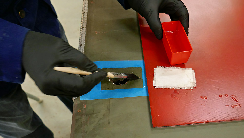
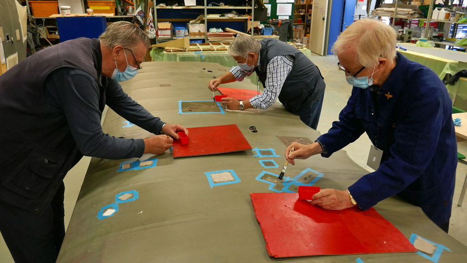
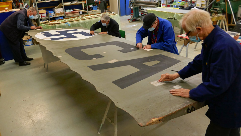
Fabric covering of Caudron C.59 wings is being patchedSunnuntai 12.9.2021 - Tuesday Club member When the Tuesday Club activities were interrupted because of the Covid-19 pandemic in March 2020, the holes and tears on the fabric covering of the lower wings of Caudron C.59 (CA-50) were being patched. The damages on the lower port wing had already been patched. The tears on the fabric covering of the starboard wing had already been sewn and the patches had been cut from linen fabric, they were waiting to be glued with shrinking varnish. There are plenty of holes to be patched on the covering of the lower wings, about 50 on both surfaces.
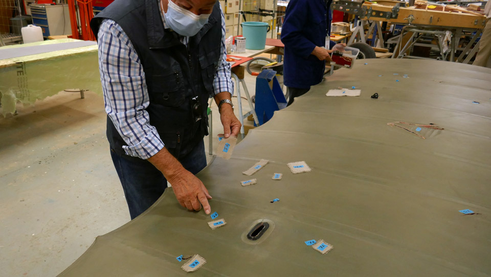
Now the Tuesday Club can continue its activities again and the Caudron’s starboard wing is underway again. First the surfaces of the fabric-covered lower wing were vacuumed and the wiped with a damp cloth. Then the correct patch had to be found for each hole on the lower wing. Fortunately the holes and the patches had been numbered, so the pairing was easy. During the 18-month break the patches had been carefully stored and none were missing.
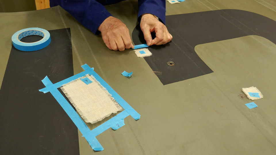
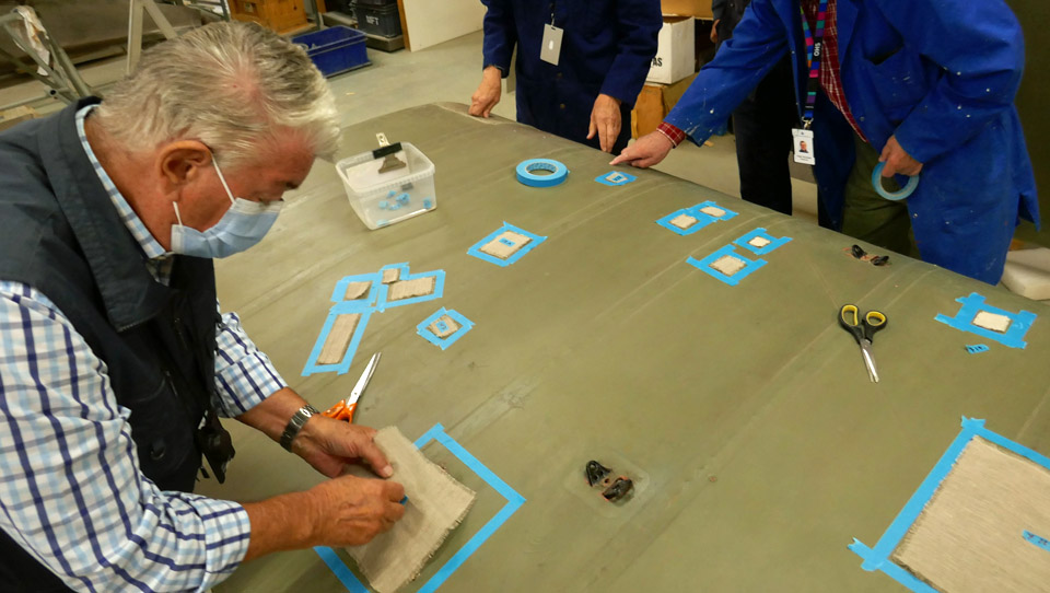
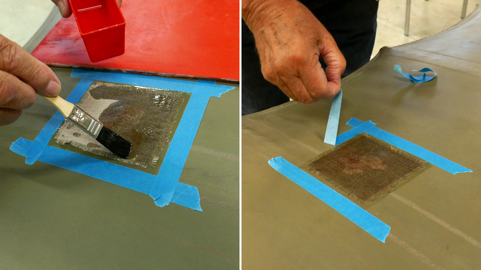
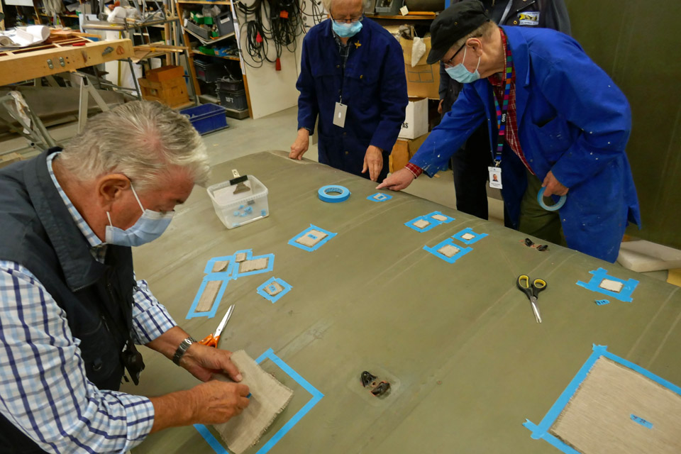
Each patch was placed on its matching hole. Then a protecting circle was taped around each patch so that the gluing varnish will not spread outside the patched area.
When all the patch areas had been surrounded with tape, nitrocellulose varnish (shrinking dope) was spread on the area inside the tape circle. The edges of each patch had been unravelled and the patches were pressed on the wet varnish. More varnish was applied on each patch so that the fabric and the unravelled edges became thoroughly wet. The unravelled edge will make the edges of the patch fasten better on the original fabric covering. This was the work method when the fabric covering was patched in the 1920s and 1930s.
The protecting tape was removed soon after the varnishing so that the glue of the tape won’t harden on the fabric surface. If the tape is left on the painted surface of the fabric covering for a long time, it is possible that the tape will leave a mark on the painted surface when it is removed.
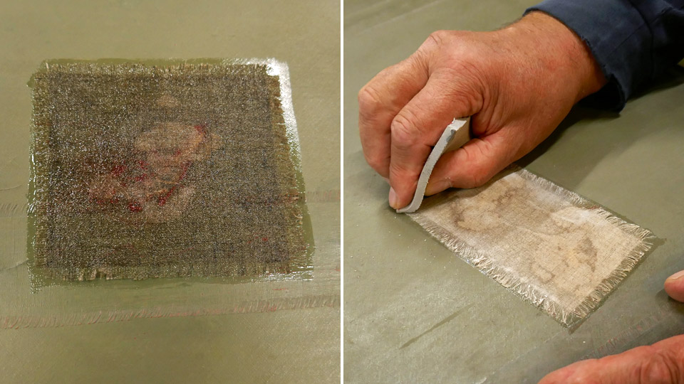
When the varnish had dried, the patches had shrunk nicely on the holes and damaged areas. The surfaces of the fabric patches and their unravelled edges were ground smooth using a fine grinding pad. The patches will be varnished and ground at least a second time so that the surface becomes very smooth before it is painted. The patched areas will be painted greyish green to match the hue of the Caudron’s wing surfaces, which have been painted in the 1920s and gained patina during the decades. Photos: Lassi Karivalo Translation: Erja Reinikainen. |
|
Avainsanat: aviation history, restoration, Caudron C.59, CA-50 |
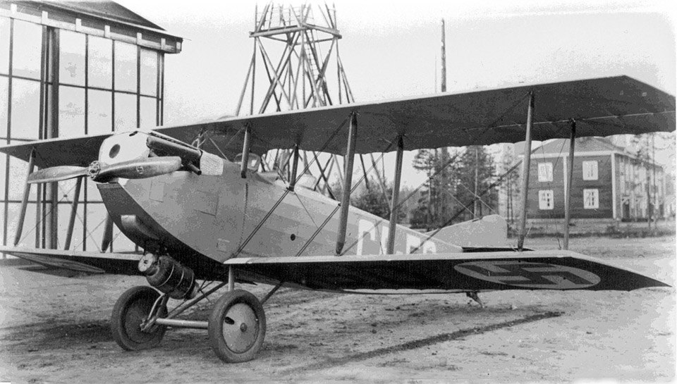
Tuesday Club activities are continuedTiistai 7.9.2021 - Tuesday Club member During the Covid-19 pandemic a small Tuesday Club team has been working on the VL Myrsky restoration project. Tuesday August 31st was a day of joy: finally, after a break of about 18 months, the other Tuesday Club activities could be continued. The main work item is the restoration of the Caudron C.59 trainer fighter, which is now in the restoration space of the Finnish Aviation Museum.
Photo: The photo archive of the Finnish Aviation Museum. However, there are still some restrictions and Covid-19 instructions from the Finnish Aviation Museum and the Tuesday Club is not able to start with full capacity. The number of workers in the restoration space is still limited and everybody working there is still wearing a mask.
In order to involve as many Tuesday Club members as possible in the Caudron restoration work, the team has been divided into two groups and works in the restoration space on Tuesdays and Wednesdays. This allows about twenty club members to work on the Caudron and on other projects, too. The Myrsky team continues to work on three days a week. The Caudron C.59 restoration is continued, now the holes on the lower wings are being repaired. About 18 months ago the lower port wing was patched and the patches were made for the starboard wing – then the Covid-19 pandemic interrupted the Tuesday Club activities. Now the patching of the starboard wing is in progress again.
The tail boom stabilizers of the Mil Mi-8P (HS-6) helicopter, which is on display on the yard of the Tuulonen shopping centre, have been brought to the Tuesday Club to be repaired. The stabilizers are partly covered with fabric and the fabric has decayed, because the helicopter has been on display outdoors since it was removed from service in 2007. The fabric covering will be renewed by the Tuesday Club team.
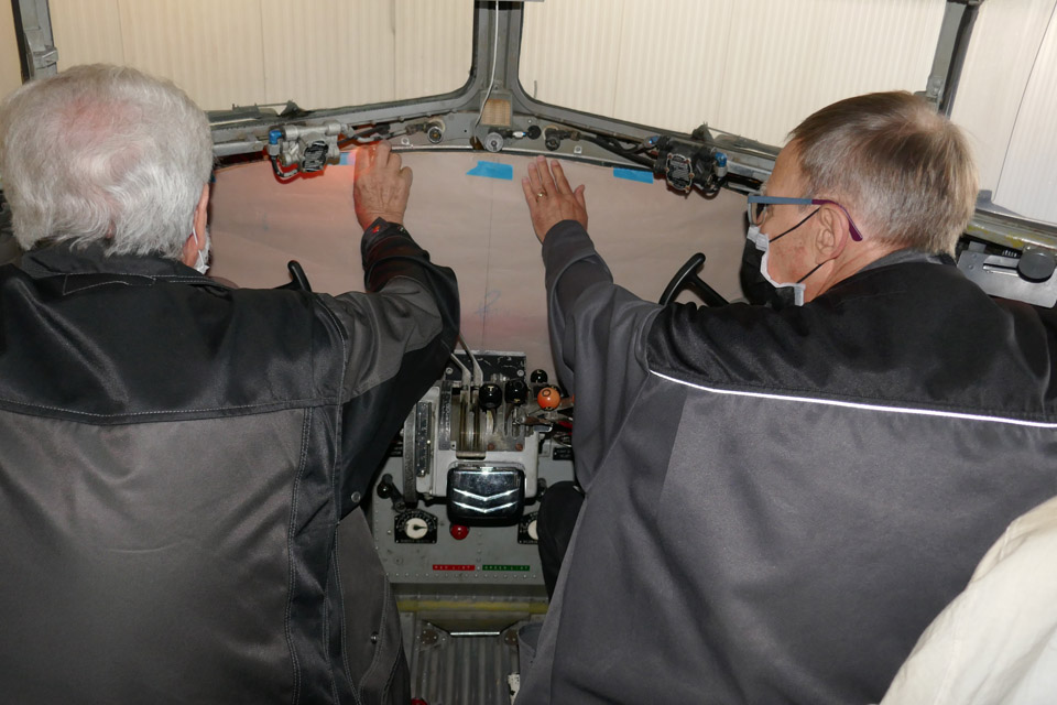
One of the most unique projects the Tuesday Club has come across is the preparation of a DC-3 instrument panel for a movie. A proper DC-3 instrument panel will not be made, but a reasonably plausible version anyway. Photos: Lassi Karivalo except if separately otherwise mentioned. Translation: Erja Reinikainen. |
|
Avainsanat: aviation history, restoration, Caudron C.59, CA-50, Mil Mi-8P, HS-6, DC-3 |
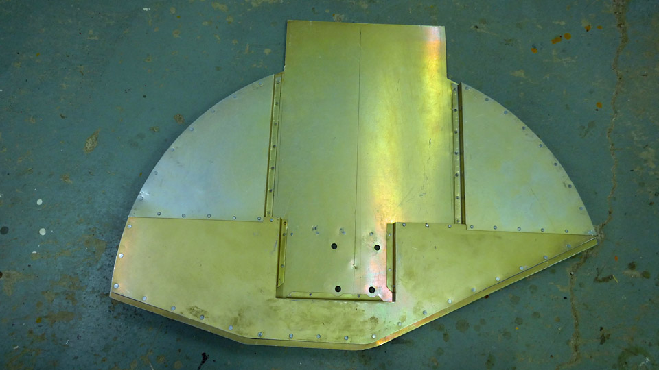
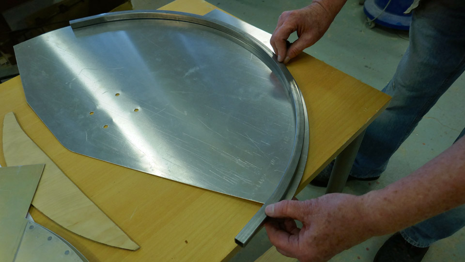
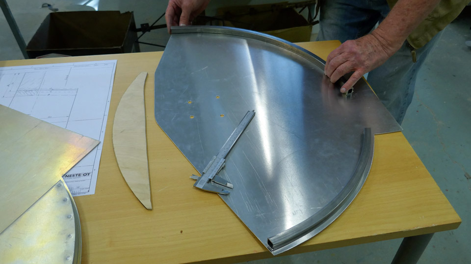
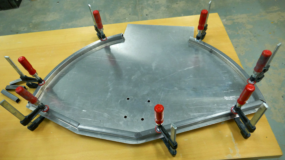
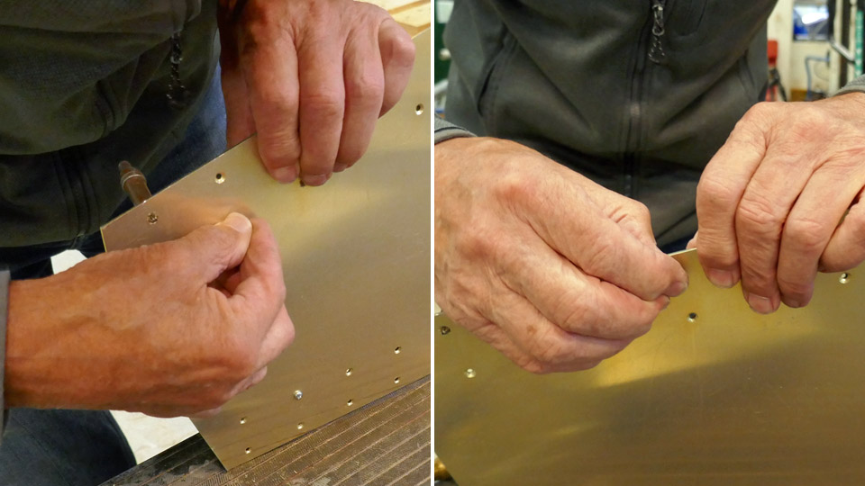
Work on Myrsky's landing gear wheel hub cover is continuedTorstai 26.8.2021 - Tuesday Club member The Tuesday club team has continued preparing the cover which is fastened on the wheel hub of the starboard wing landing gear on the VL Myrsky II (MY-14). At the moment the metal support is being made for the inner edge of the cover. The support circles the edge of the cover, and it is made of 15 mm thick square steel tube. It is fastened at a 10 mm distance from the edge of the cover.
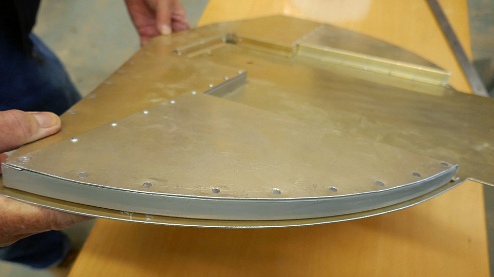
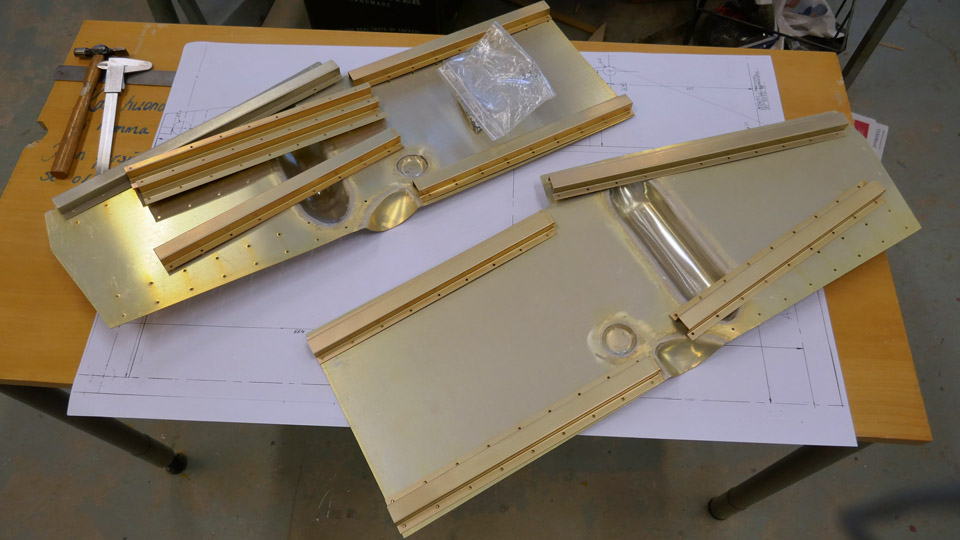
The square tube is a supporting frame for the cover, cut from aluminium plate, and it also forms a fastening surface for the stiffeners which are fastened on the inner side of the cover. The stiffener plates, cut from aluminium plate, are riveted on the cover so that the square tube is between the cover and the stiffener plate. The stiffener plates are waiting to be assembled. The stiffeners on the test wing’s wheel hub have already been riveted. The wheel hub cover of the test wing has been used as a model when the actual covers for the landing gear are made.
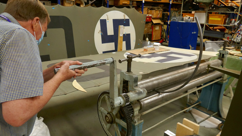
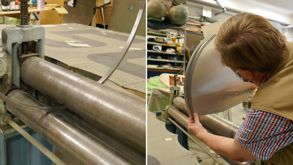
The upper edge of the wheel hub cover is curved, and the square tube had to be modified in a mangling machine to make it match the cover shape. The shape was modified step by step. When the square tube began to curve, its shape was compared to the curved edge of the cover and mangled again. When the desired curved shape had been reached, the square tube was cut into pieces which will be fastened on the cover’s upper edge.
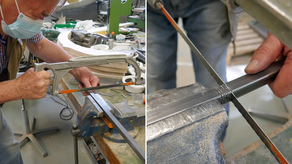
The lower edge of the wheel hub cover is not curved but angular. A piece of the square tube was cut for the cover’s lower edge. To modify the square tube into an angular piece, a cleft was sawed at the point where the cover edge has its steepest angle. Several clefts were made where the slighter angle is. The tube was bent, using the clefts, to meet the shape of the cover’s lower edge.
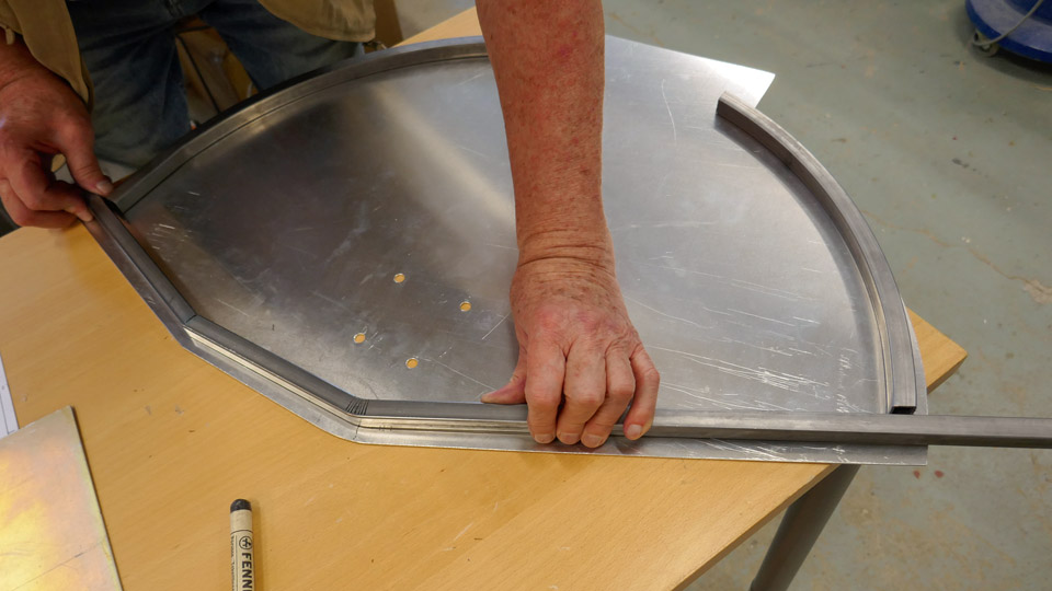
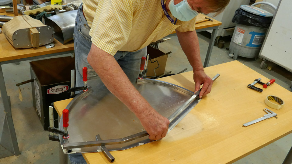
The following phase was to mark with tape the line of the corner joint, where the curved square tube on the upper edge of the cover meets the angular square tube of the lower edge. The tube ends were cut slanted according to the marked line. The slanted tube ends were placed against each other and fastened on the cover plate with clamps. At first the tube ends will be lightly welded together so that the whole tube frame can be moved from the aluminium cover plate for the actual welding work. When this has been done, the square tube forms a complete supporting frame along the edge of the wheel hub cover. Photos: Lassi Karivalo Translation: Erja Reinikainen. |
|
Avainsanat: aviation history, restoration, VL Myrsky, MY-14 |
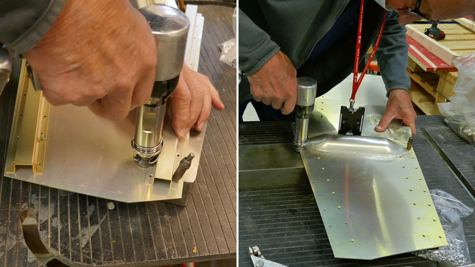
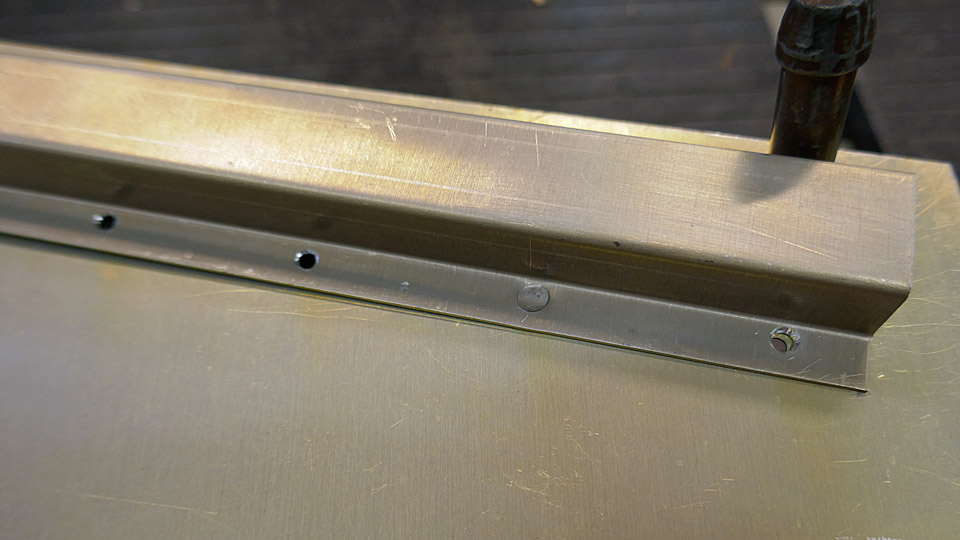
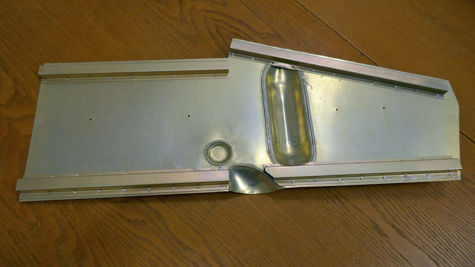
Stiffeners were riveted on cover of landing gear oleo strut on Myrsky's starboard wingMaanantai 23.8.2021 - Tuesday Club member The Tuesday Club team has continued its work on the covers for the Myrsky fighter’s landing gear on the starboard wing. U-profile stiffening battens were riveted on the cover of the oleo strut, which was otherwise ready. The stiffeners were cut from aluminium plate and pressed into shape. They are riveted on the inside edge of the cover. The cover and stiffeners have already been chromated.
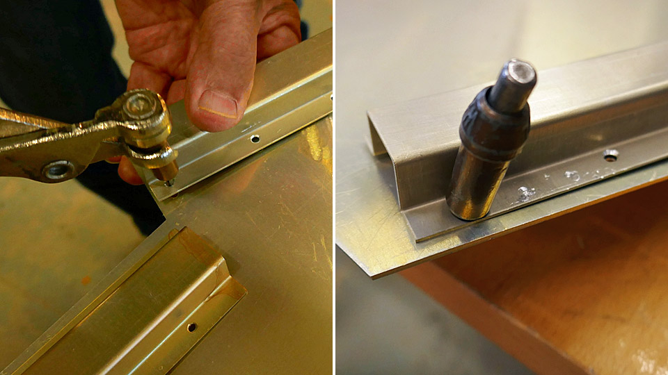
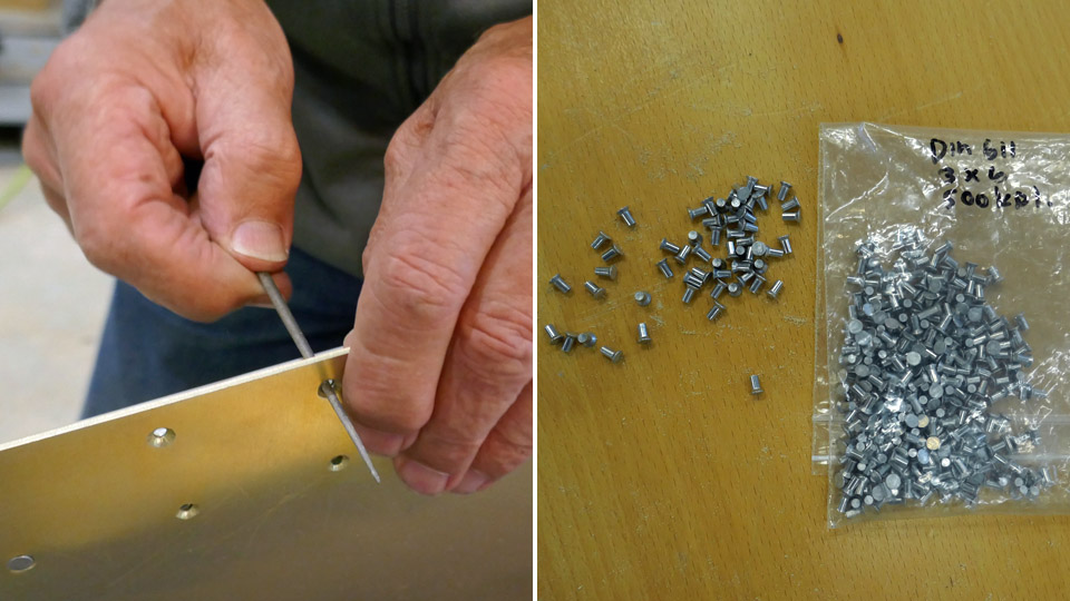
The riveting was started by fastening the first of the four stiffening battens on the edge of the cover with cleco fasteners. Clecos, which are fastened in the rivet holes with nose pliers, are used for the temporary fastening of work pieces which will be riveted or welded together. In spite of the cleco-fastening, the rivet holes had to be slightly shaped with a round file to make the rivets slide nicely into their holes.
The rivets used were 3x6 mm flathead rivets. The stiffeners were riveted on the cover plate rivet by rivet. A compressed air riveting gun was used. All four stiffeners have now been riveted. The cover plate has been preliminarily assembled on the oleo strut of the starboard wing. It fits nicely into its place. Photos: Lassi Karivalo Translation: Erja Reinikainen. |
|
Avainsanat: aviation history, restoration, VL Myrsky, MY-14 |
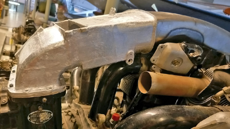
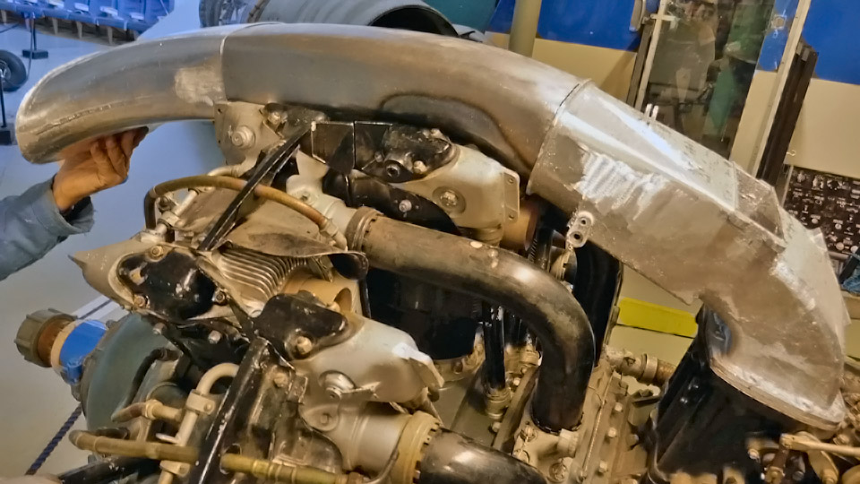
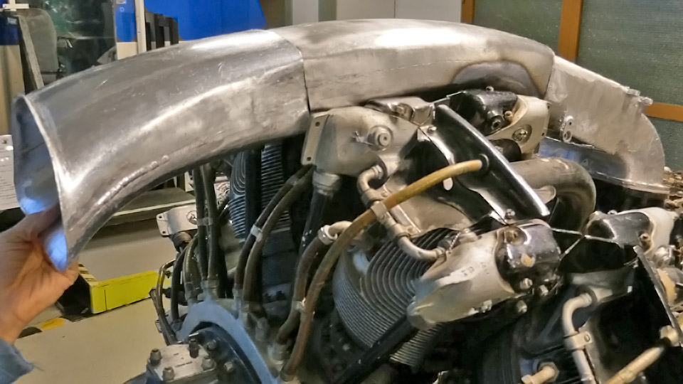
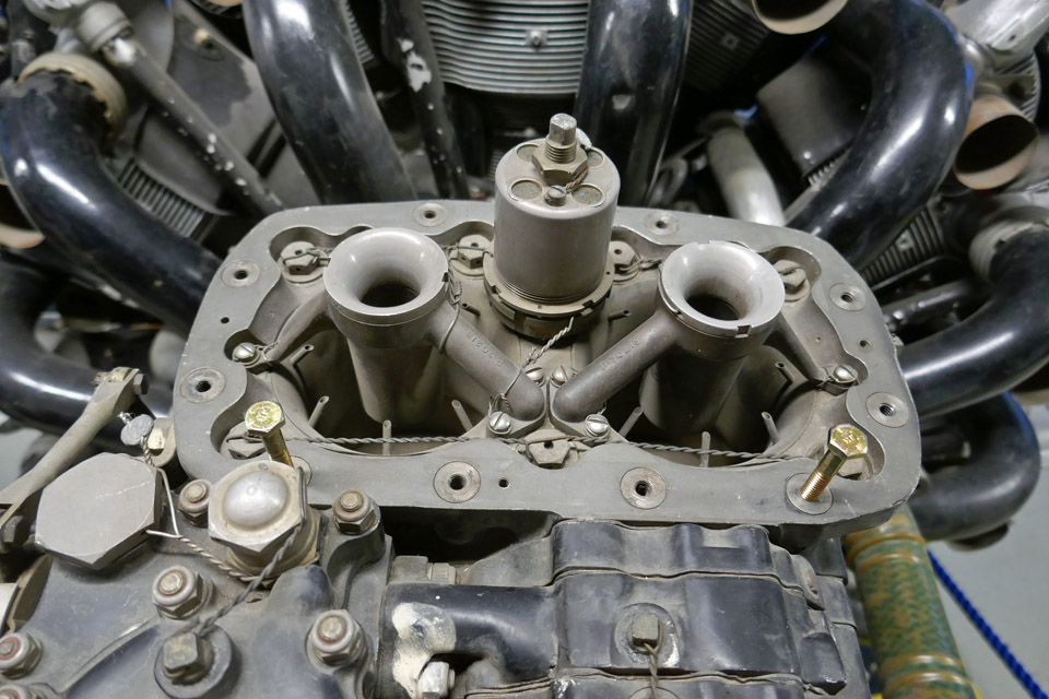
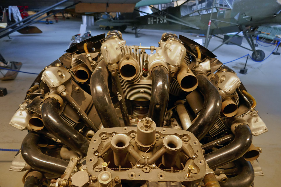
Works on Myrsky carburettor air intake and NACA-ringTiistai 22.6.2021 - Tuesday Club member The half-finished air horn and air intake ducts have been preliminarily assembled on the VL Myrsky II which is under restoration. The Myrsky had a Pratt &Whitney R-1830 radial engine and a similar engine is available at the Finnish Aviation Museum. Fortunately it has been possible to test the assembly at the museum and there is no need to travel to the Air Force Museum at Tikkakoski, where a similar engine has already been installed on the Myrsky’s (MY-14) fuselage.
Holes for the fastening bolts were drilled on the cast aluminium air horn and the air horn was fastened with a couple of bolts onto the carburettor of the engine, located in the museum hall. It fitted nicely into its place. Then the two air duct sections could be assembled into place between the air horn and the NACA-ring.
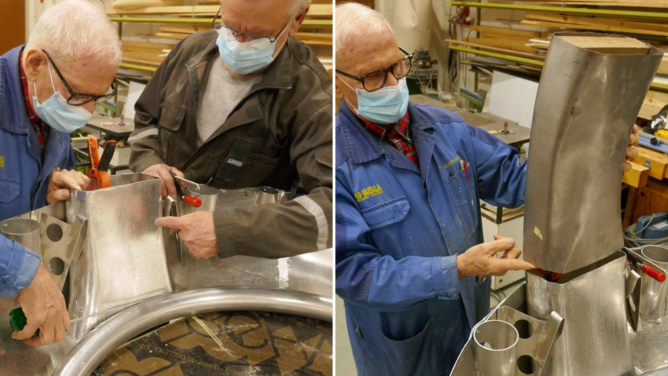
The Tuesday Club team noticed that the section of the air duct, made of steel plate because of its location above the hot engine, did not fit properly. The reducers made on its lower part were too shallow and the air intake duct couldn’t be pressed sufficiently deep between the cylinder head covers. The air intake duct was heated using a welding flame and shaped to fit better. Then the two air intake duct sections were assembled above the engine and fastened on the air horn. Even when half-finished it is a great sight!
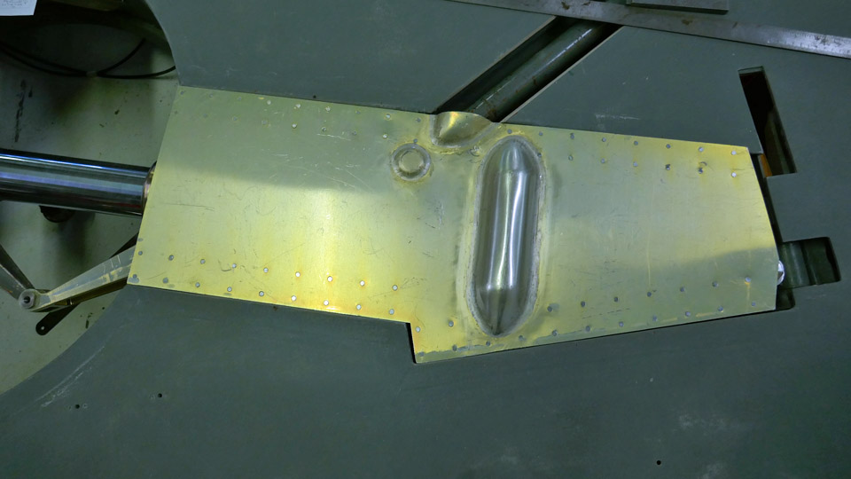
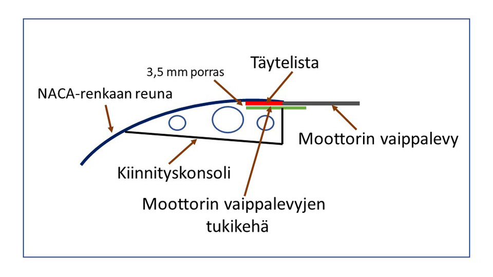
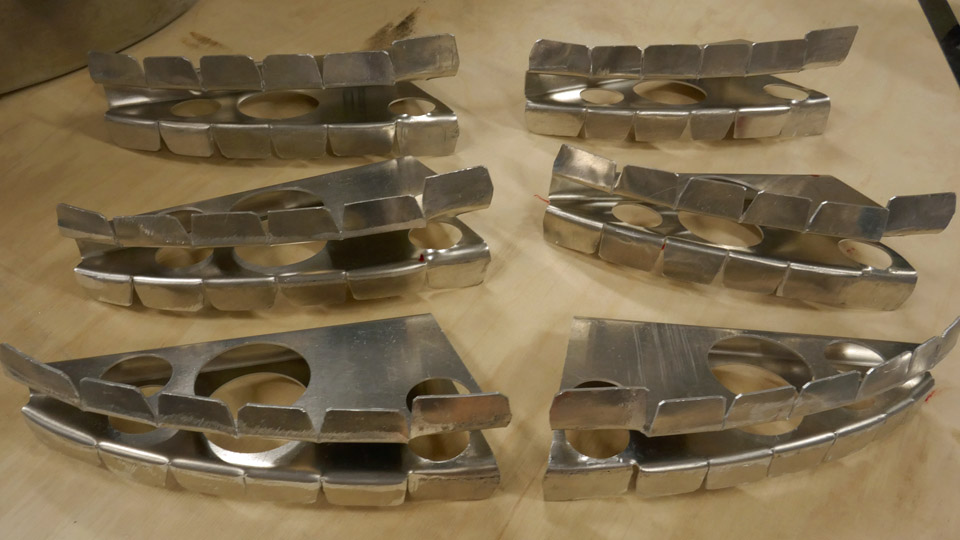
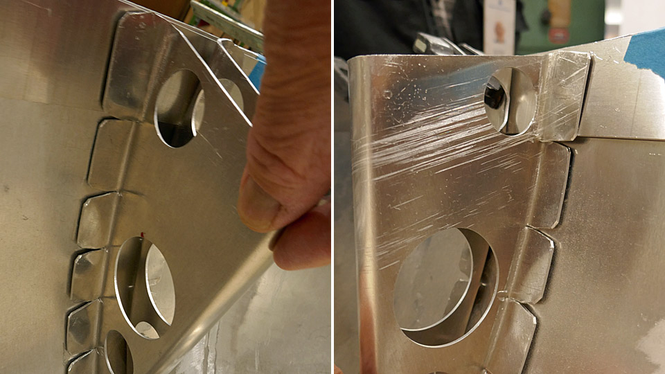
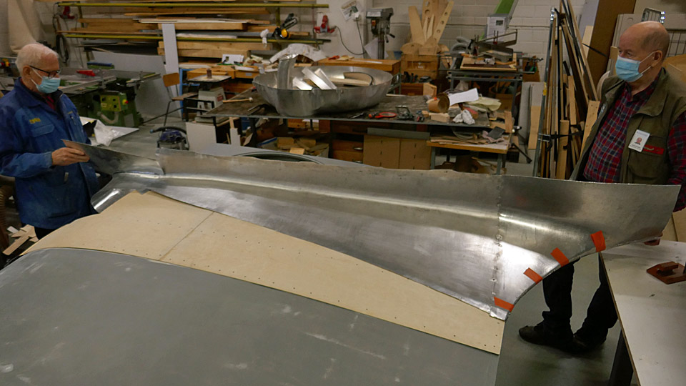
The consoles of the NACA-ring, which are needed to fasten the ring on the brackets on the cylinder heads, had to be modified before riveting on the edge of the NACA-ring. Especially the console hems have needed shaping. The console is riveted on the NACA-ring by its hem. The hem has to meet the curved shape of the NACA-ring and to take into account the filler batten, which is a 2,5 mm aluminium batten riveted on the edge of the NACA-ring, and the 1,0 mm aluminium supporting frame of the engine fairings. The supporting frame is 75 mm wide, and it is riveted on top of the filler batten so that it extends 32 mm outside the edge of the NACA-ring. It forms a shoulder on which the edge of the detachable engine fairing rests and meets the edge of the NACA-ring in a butt joint. There is a very general overview picture of this structure attached.
Translation: NACA-renkaan reuna = Edge of NACA-ring, 3,5 mm porrastus = 3.5 mm offset, Kiinnityskonsoli = Console, Moottorin vaippalevyjen tukikehä = Supporting frame of detachable engine fairing rests, Täytelista = Filler batten, Moottorin vaippalevy = Detachable engine fairing rests.
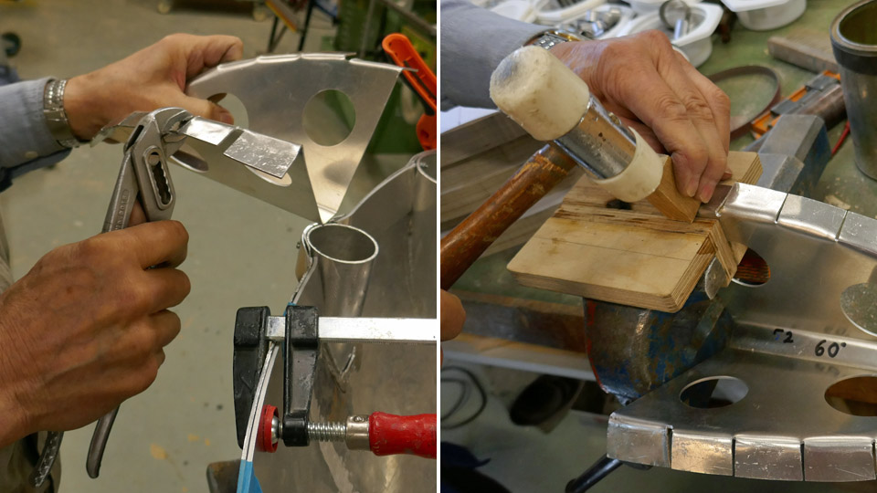
The hems of the NACA-ring consoles were shaped using pliers and a plastic-headed hammer and a piece of wood. A 3,5 mm offset was made on the upper end of the console for the filler batten and the supporting frame. All console hems have now been shaped and are ready to be riveted into place. Before that can be done, the filler batten and the supporting frame on top of it will have to be riveted onto the edge of the NACA-ring. The supporting frame is made of four sections and the sections are ready to be installed.
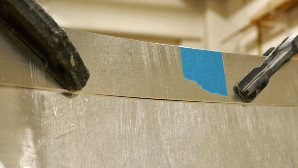
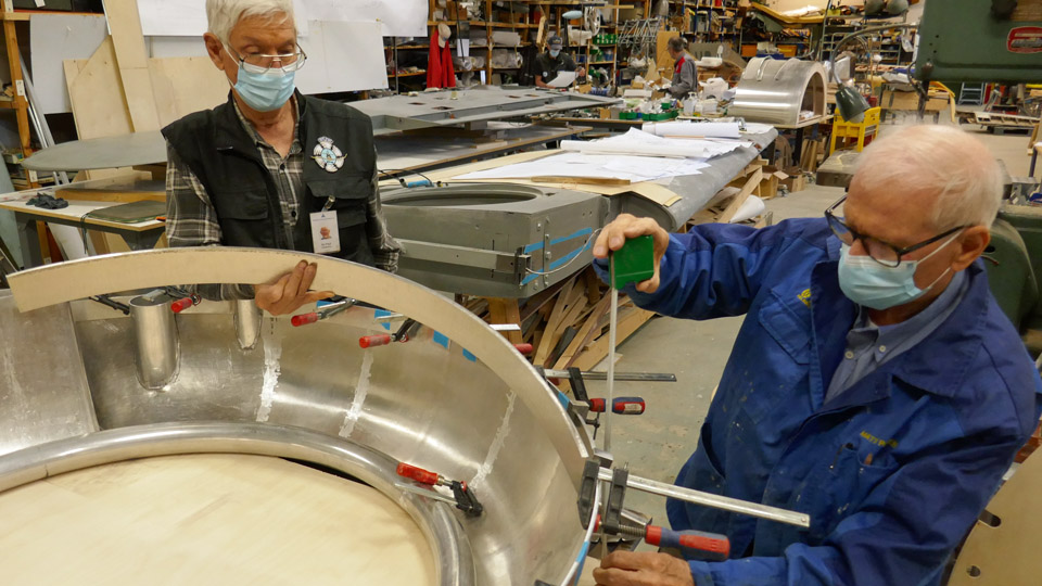
Up to now the filler batten has been fastened on the upper edge of the NACA-ring with clamps. Now it is debated how the riveting of the filler batten and the supporting frame on the NACA-ring edge will be done so that the filler batten settles exactly to the same level as the NACA-ring’s edge. Photos: Lassi Karivalo. Translation: Erja Reinikainen. |
|
Avainsanat: aviation history, restoration, VL Myrsky II, MY-14 |
Myrsky's starboard wing half was turned for installing landing gearSunnuntai 13.6.2021 - Tuesday Club member The assembly of the landing gear has been started on the wing halves of the VL Myrsky II (MY-14), which is under restoration at the Tuesday Club. Thorough test assembly has already been done on the test wing which was prepared in the Myrsky-project. The test wing is a 2,5 metres long root piece of the wing, meant mainly for testing the landing gear installation. The landing gear will first be assembled on the starboard wing half.
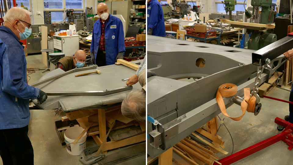
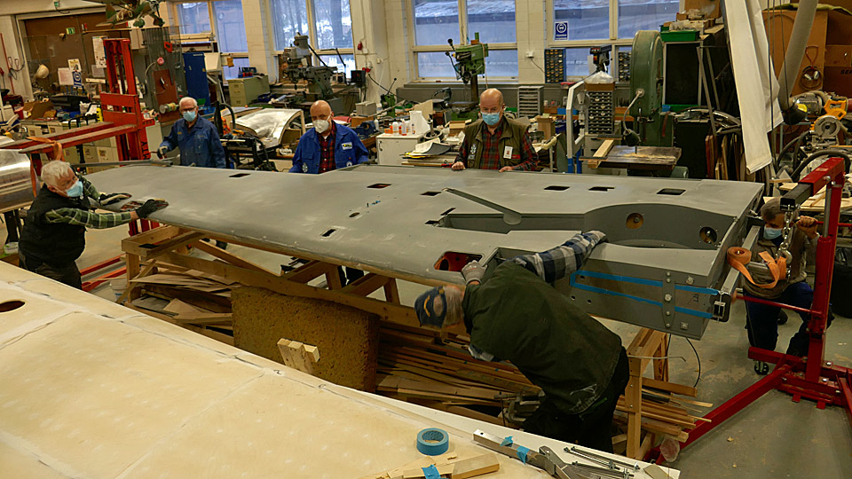
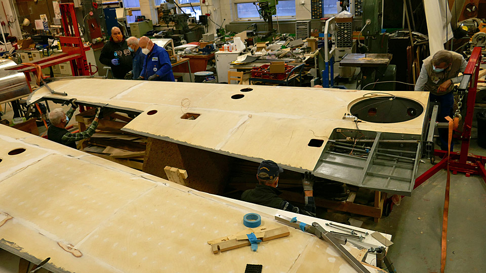
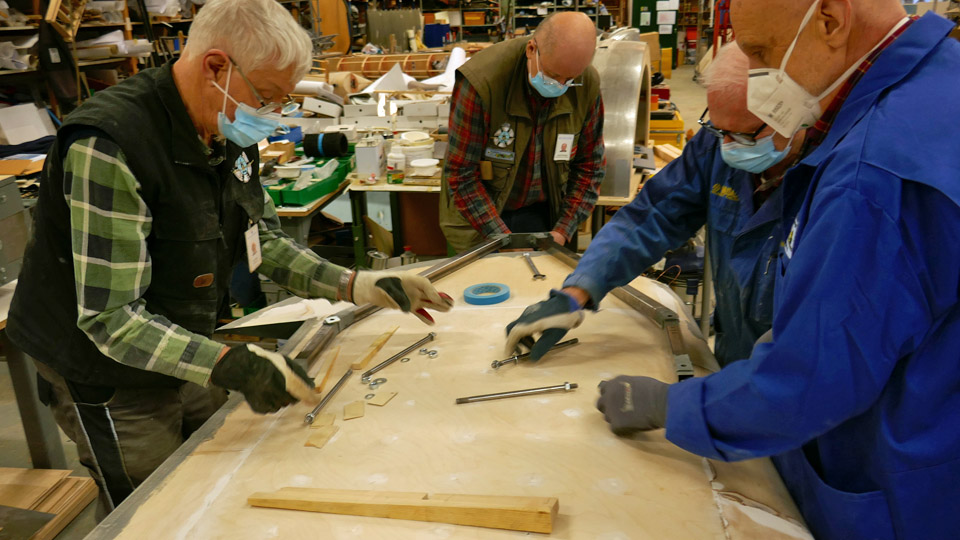
The wing halves were painted with undercoat paint and after this work they remained on the worktable the upper side up. First the starboard wing had to be turned so that the landing gear well is facing upward, and the landing gear can be installed. The wing halves have already been turned around several times during the different work phases. For this purpose steel supports have been made for the wing tip and the wing root and they are used to support the wing when it is lifted and turned.
Two lower photos: move the cursor over photo and you will see more photos! The turning supports were fastened on the wing tip and the wing root. Then a lifting device was moved to both ends of the wing and the lifting devices were connected to the steel supports with cargo straps. Then the lifting devices were pumped, and the wing was lifted in the air, supporting it manually all the time. When the wing had been lifted high enough, the wing was tilted in order to turn it around. The wing was carefully manoeuvred onto one side by supporting it from the other side. When the wing had been turned, it was lowered back on the worktable and it was placed horizontally by supporting it at the ribs.
Photos: Jorma Laakkonen. Photo: Jorma Laakkonen. Now the landing gear well was facing upwards, and the landing gear assembly could be started, following the procedure developed when testing the gear on the test wing. The first preliminary test was to place the landing gear oleo strut in the well with its wheel hub and axle. At the same tame the wheel well doors were fitted into place. These include the diagonal support door, the oleo strut door, the wheel hub door and the opening door, which is fastened on the fuselage side edge of the wheel well. All parts seemed to settle nicely into their places.
Photo: Jorma Laakkonen. Now there is ahead the demanding work of fitting all the hinges and fastenings of the starboard landing gear into place so that the landing gear extends and retracts smoothly. The aluminium covers will also have to be assembled into place on the diagonal support, on the oleo strut and on the wheel hub. Another challenge is to fit into place the aluminium cover on the fuselage side of the wheel well and to make its opening and closing mechanism work as planned. This door is opened automatically by a spring lever when the landing gear is taken out. When the landing gear is retracted the wheel presses against a pin in the mechanism and closes the door. Photos: Lassi Karivalo except if otherwise mentioned. Translation: Erja Reinikainen. |
|
Avainsanat: aviation history, restoration, VL Myrsky II, MY-14 |
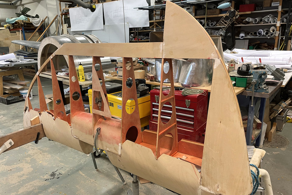
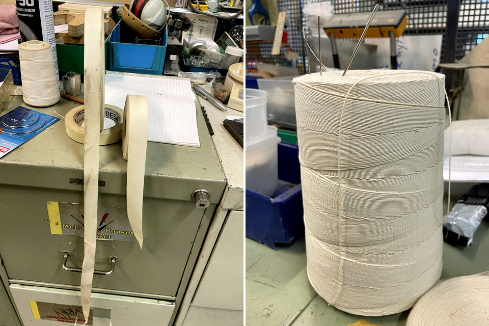
MY-14's vertical stabilizer gets its fabric covering webbing ribbonsSunnuntai 6.6.2021 - Tuesday Club member When the webbing ribbons for the fabric covering had been sewn on the horizontal stabilizer ribs of the VL Myrsky II (MY-14), the sewing work continued on the vertical stabilizer. The vertical stabilizer has a wooden structure, according to the original drawings.
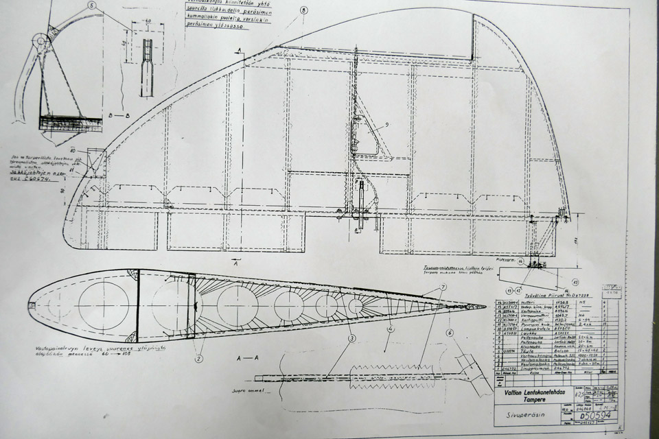
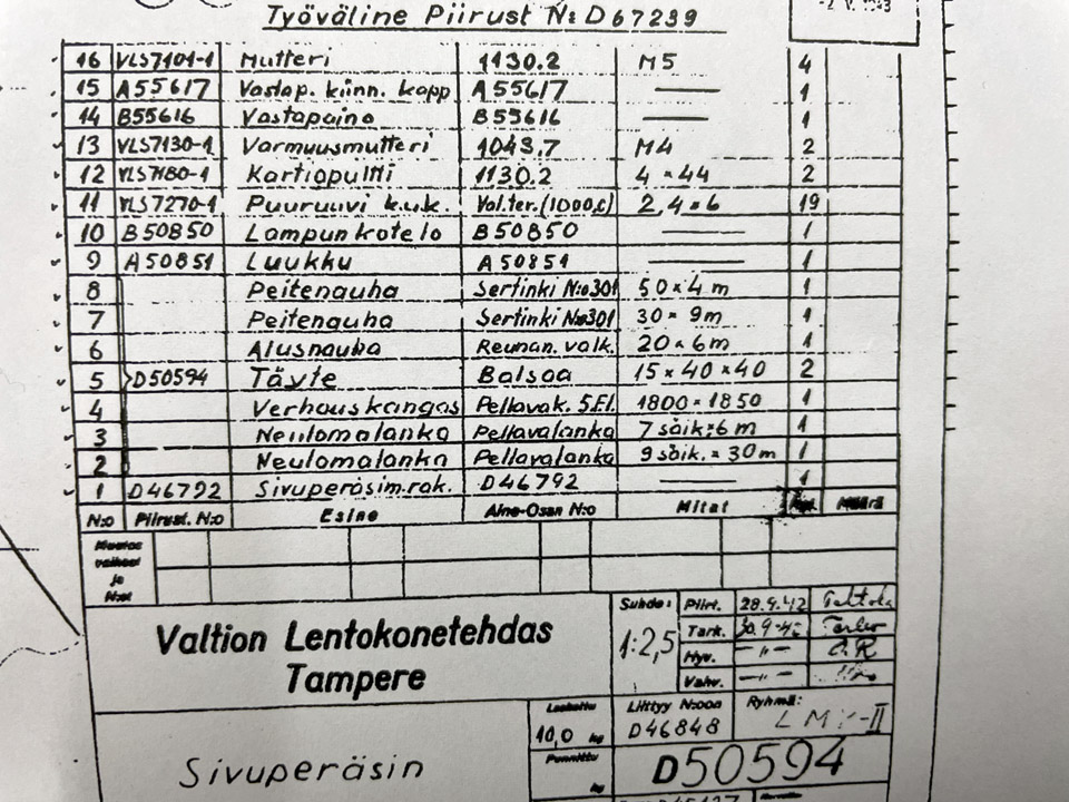
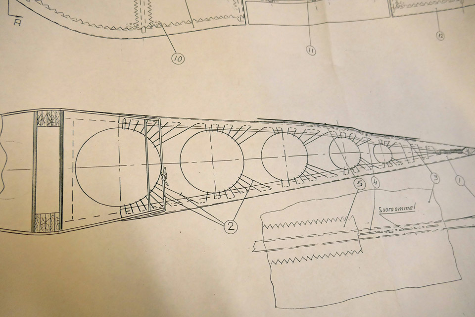
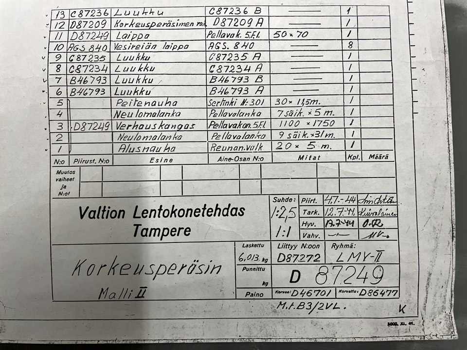
Photo: Heikki Kaakinen. The Tuesday Club team used the original drawing of the vertical stabilizer, prepared by the State Aircraft Factory and dated 30.9.1942, as instructions for the work. The drawing shows very well how the ribbons must be sewn. The bill of materials on the drawing shows a detailed list of the accessories needed in the work. The list includes the covering fabric, the webbing ribbons, cover ribbons and sewing threads. A 20 mm wide diagonally woven linen ribbon was used as the webbing ribbon.
Photo: Heikki Kaakinen.
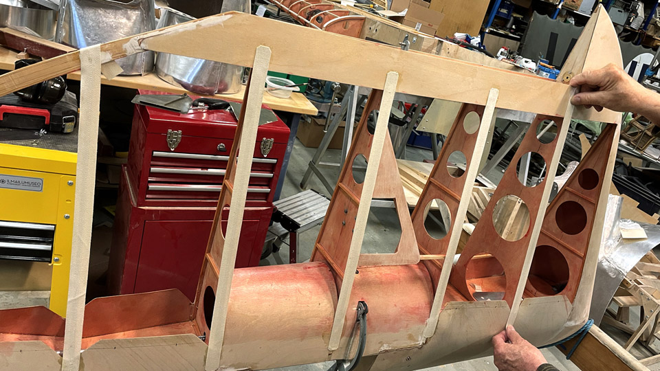
Photo: Heikki Kaakinen. In order to keep the webbing ribbons in place on the rib of the vertical stabilizer when doing the sewing, the ribbon was stretched on the rib and its one end was glued on the plywood of the leading edge and the other end on the plywood of the trailing edge. Contact glue was used in this work.
Left photo: Heikki Kaakinen. One more work phase had to be completed before the actual sewing could be started. The edges of the plywood sheet covering the leading edge had to be bent inwards so that the edges won’t chafe the fabric covering and gradually damage it.
Photo: Heikki Kaakinen.
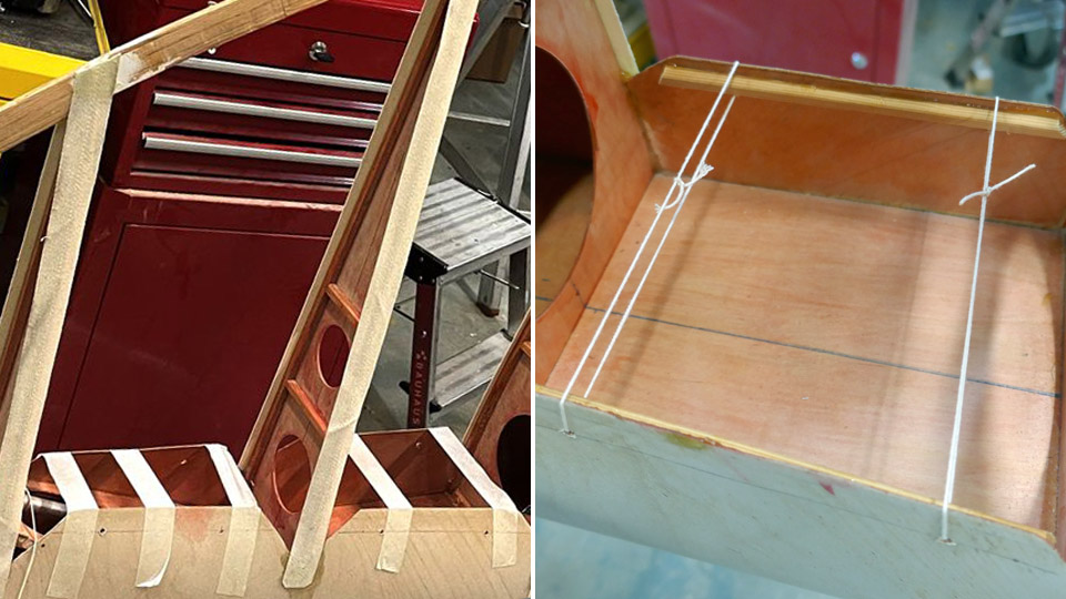
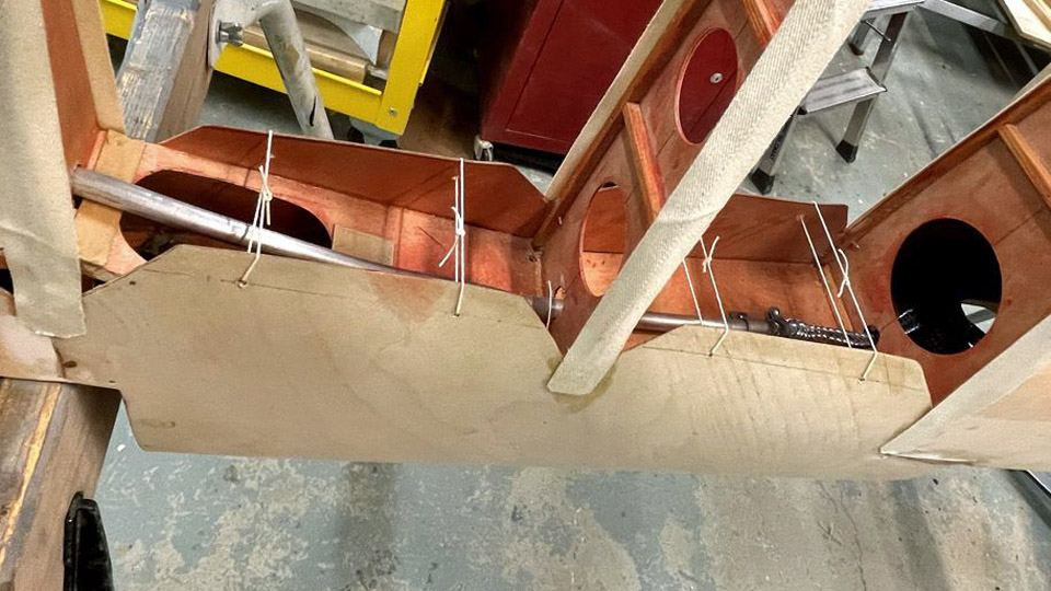
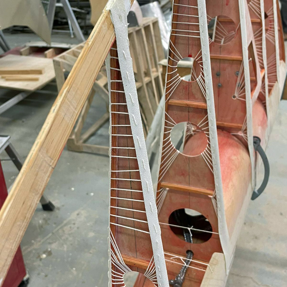
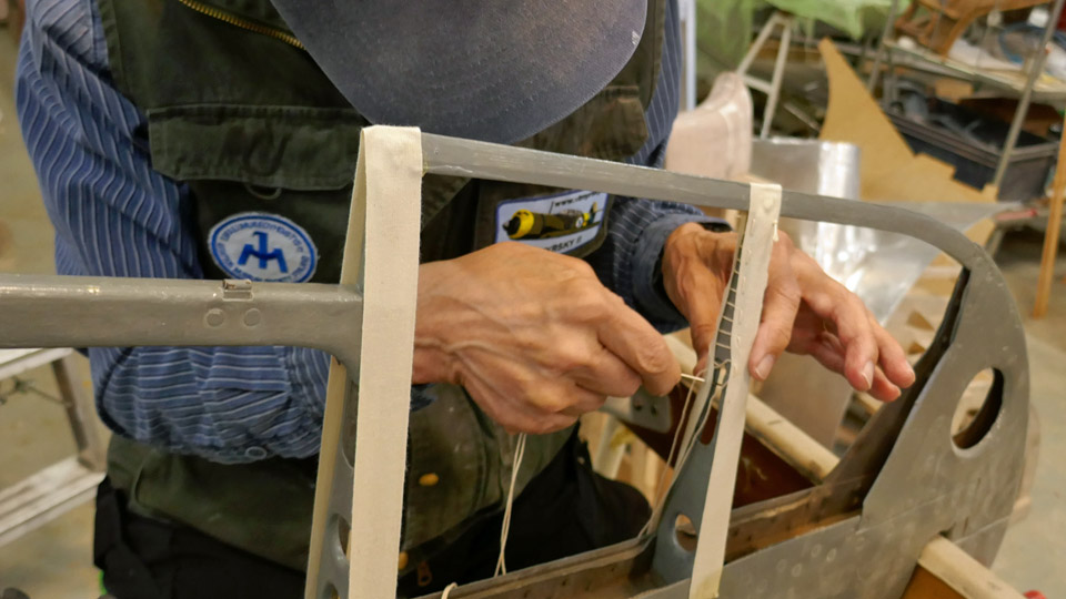
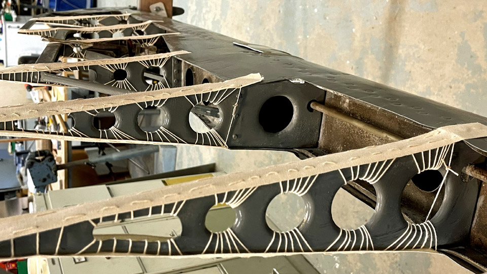
Photo: Heikki Kaakinen. To bend the plywood edges, 3 mm holes were drilled where the drawing indicated. Then the edges were bent against each other and tied temporarily into this position using painter’s tape. Linen thread was pulled through the drilled holes and then the threads were tied together into a tightening loop, connecting the edges of the plywood. Then the supporting painter’s tapes could be removed, and the sewing of the webbing ribbons could be started.
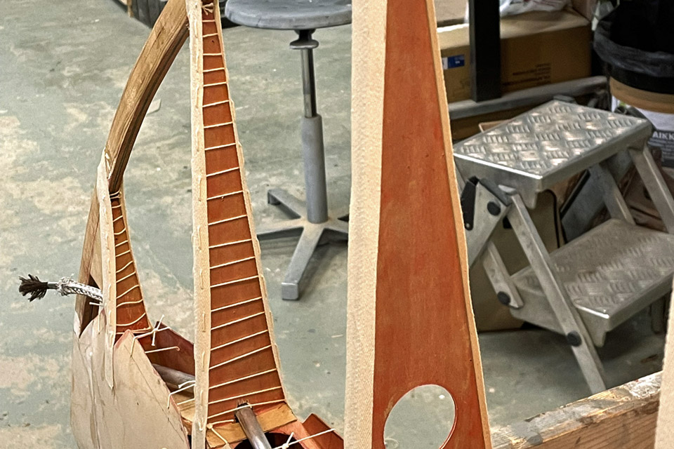
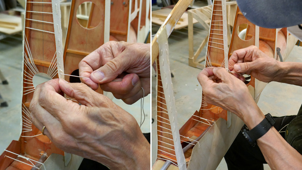
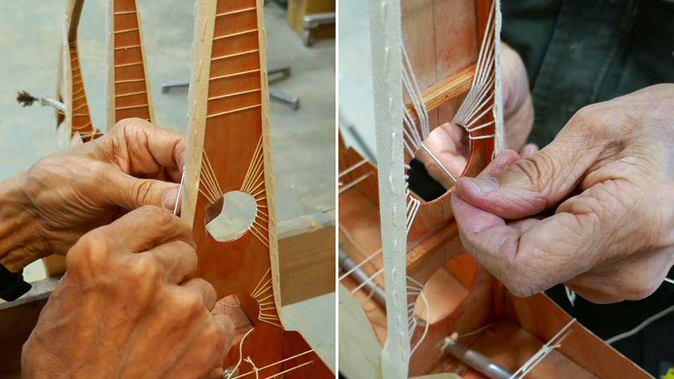
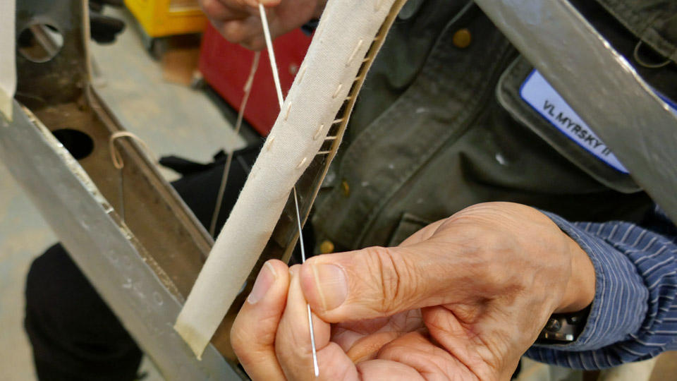
Photo: Heikki Kaakinen. The webbing ribbons for the fabric covering of the vertical stabilizer were sewn in a similar manner as on the horizontal stabilizers. At the tapered part of the rib the edges of the ribbon were stitched together. At the broader part of the rib, where the round lightening holes are, the thread was slipped through the lightening hole and fastened on the ribbon’s edge on the other side and repeating back again. A radial pattern of the threads was formed in the lightening hole. Now the vertical stabilizer had its webbing ribbons in place. Photos: Lassi Karivalo except if otherwise mentioned. Translation: Erja Reinikainen. |
|
Avainsanat: aviation history, restoration, VL Myrsky II, MY-14 |
Webbing ribbons for fastening fabric covering of Myrsky's horizontal stabilizer are sewnTiistai 1.6.2021 - Tuesday Club member The VL Myrsky II fighters had originally wooden horizontal stabilizers. The aeroelastic flutter caused the damaging and even breaking of the stabilizers. Therefore the Myrsky’s horizontal stabilizers were replaced with metal stabilizers, which endured the flutter. The documents concerning the MY-14 which is under restoration don’t mention whether the aircraft got metal horizontal stabilizers before it was written off. However, the board of the Myrsky restoration project decided that the restored MY-14 would have metal horizontal stabilizers. One of the reasons for this was that there were original metal stabilizers available, but somewhat damaged and without covering.
Photo: Heikki Kaakinen. The original horizontal stabilizers with aluminium structure have already been repaired and painted by the Tuesday Club and they have been waiting for the fabric covering for a while. The metal stabilizers are covered with fabric in the same way as the corresponding wooden stabilizers. First fabric webbing ribbons are sewn on the ribs of the stabilizer. The fabric covering is fastened on these ribbons by sewing. The fabric is tightened using several layers of nitrocellulose varnish and finally painted according to the aircraft’s paint scheme.
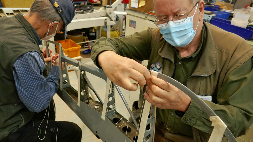
Photos: Heikki Kaakinen. The Tuesday Club team has now started the sewing of the webbing ribbons on the MY-14’s horizontal stabilizers. To make the work easier, one of the stabilizers was fastened into an upright position against two trestles. The first step was to stretch a 20 mm wide linen upholstery webbing ribbon on the stabilizer’s ribs. This was done by gluing the ends of the ribbon on the rib at the leading edge. This way the ribbon will stay in place when sewing it onto the ribs.
After the gluing the sewing could be started. The instruction drawing for sewing the ribbons on the wooden horizontal stabilizers was applied, because the instructions for the metal stabilizer have not been preserved. According to the instructions multithreaded 0,5 mm linen thread was used in the sewing work.
The sewing work was started at the trailing edge end of the rib. The edges of the ribbon stretched on the upper and lower edge of the rib were stitched together. This was the method used at the tapered end of the rib where there are no lightening holes.
When the work reached the broader part of the rib where the round lightening holes are, the sewing method was changed. Now the thread fastened to the edge of the ribbon was slipped through the lightening hole and to the other side to the ribbon’s edge, and back again. The webbing ribbon was sewn onto the rib following the original instructions, weaving the thread through the lightening hole.
Photo: Heikki Kaakinen. When the ribbons had been sewn on all the ribs of one stabilizer, the procedure was repeated on the other stabilizer. Now the horizontal stabilizers are ready for fastening the fabric covering. In the original drawing’s instructions the fabric quality has been defined as linen fabric 5.F.I. Photos: Lassi Karivalo except if otherwise mentioned. Tranlation: Erja Reinikainen |
|
Avainsanat: aviation history, restoration, VL Myrsky II, MY-14 |
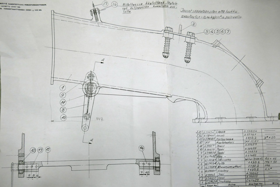
Myrsky engine's air horn and air intake are madePerjantai 28.5.2021 - Tuesday Club member The air flow entering an aircraft’s carburettor is controlled in the air horn, which is attached to the carburettor. When necessary, there is an air intake duct connected to the air horn. This is the case in the VL Myrsky II fighter, among others. In the Myrsky the two-sectioned air intake duct is connected to the air intake, located at the top of the NACA-ring, and is led between the upper cylinders to the air horn of the two-throat carburettor behind the radial engine. The suction air flow is controlled with the damper located in the air horn as well as the warm air flow, which comes through the engine space and protects the carburettor from freezing.
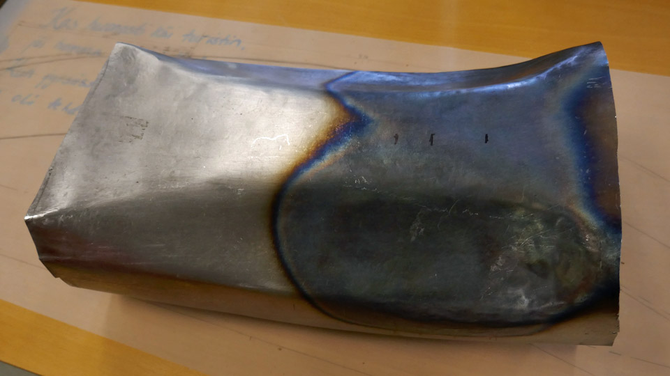
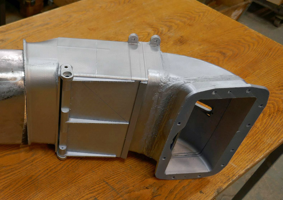
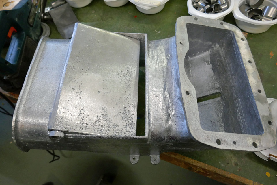
The Myrsky’s air horn is made of cast aluminium. The front piece of the two-section air intake duct, which is fastened on the NACA-ring, is made of aluminium plate. The tail section of the air intake duct is made of steel plate because it is located at a hot place between the cylinders. The tail section of the duct also connects the front section of the air intake duct to the air horn and is fastened to them with fastening clamps.
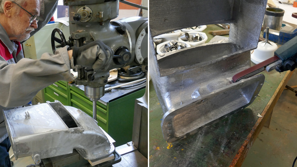
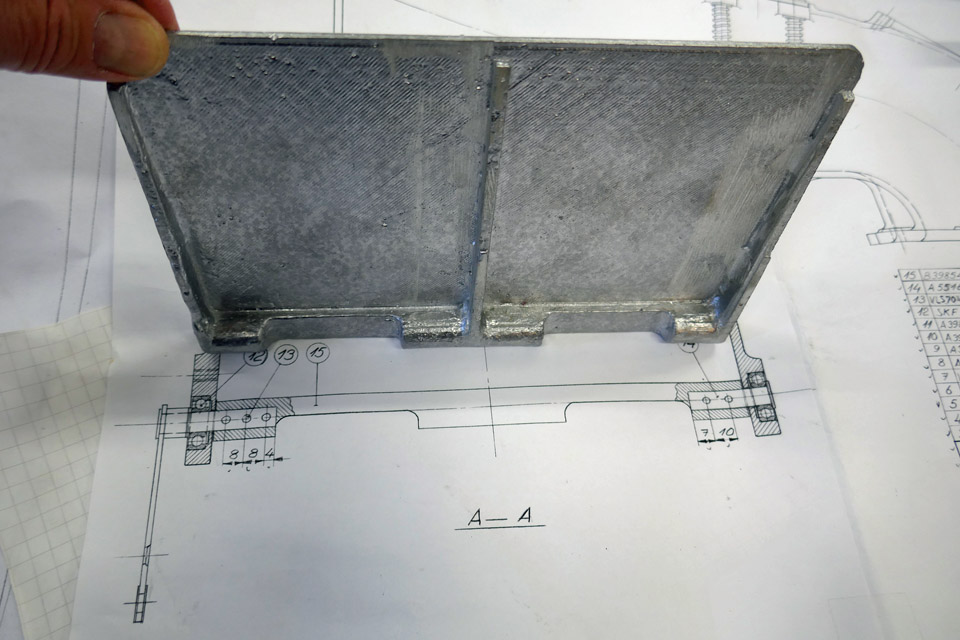
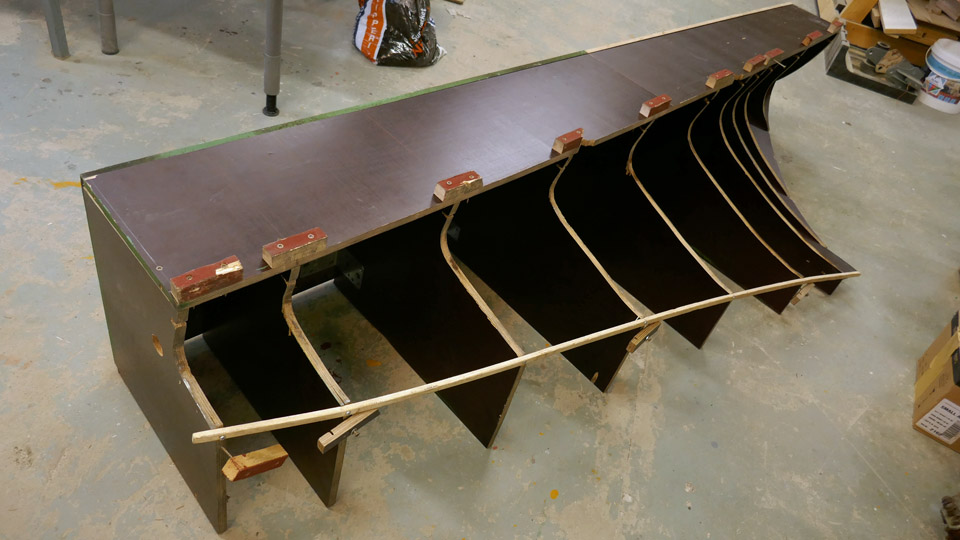
No original Myrsky engine’s air horn or parts of the air intake duct have been preserved and they had to be made in the restoration project of the MY-14. The sections of the air intake duct have already been made. The front section of the duct was made according to the drawing from 1,0 mm thick aluminium plate, using a mould. The tail section was made from 1,0 mm thick steel plate. The sections of the air intake duct have been fitted into place and the front section of the duct is being fastened to the opening in the NACA-ring.
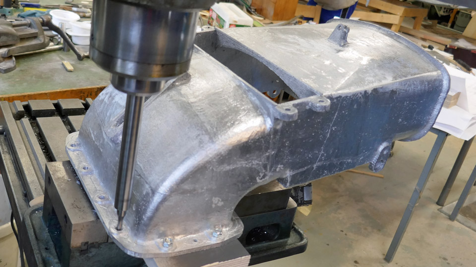
The SASKY Municipal Education and Training Consortium at Sastamala helped to manufacture the air horn from cast aluminium. They were interested in the ongoing Myrsky restoration project and asked if there was some restoration work which could be made as 3d-printing by the SASKY students. The Tuesday Club team suggested that they could make the rather difficult air horn - and they accepted the challenge.
Photo: SASKY
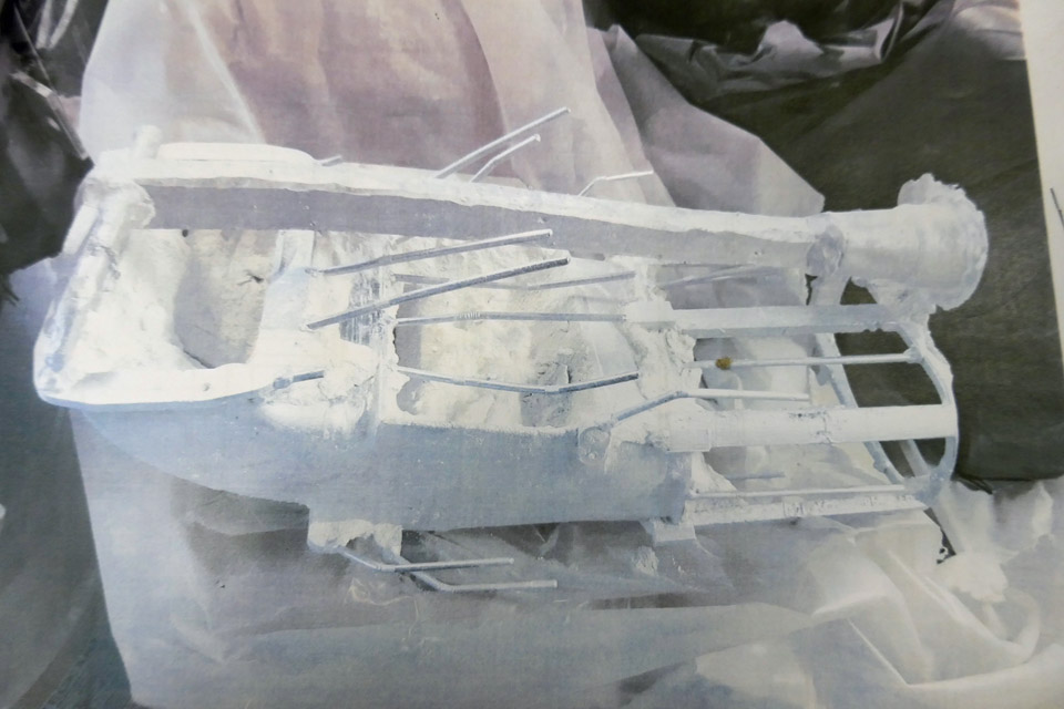
The project was started at SASKY by 3d-printing a plastic 1:1 scale model of the Myrsky’s air horn according to the drawings. Then the actual cast mould for the aluminium cast was made based on the 3d-print. The 3d-printed model was dipped several times in a ceramic solution and a ceramic layer was formed, layer by layer, on the plastic model. Flow channels and air extract were also made on the cast mould. Then the plastic 3d-model was melted from inside the ceramic shell, and the cast mould for the air horn was ready. The liquid AlSi 12 aluminium was poured into the mould. When the aluminium had cooled the mould was broken and the flow channels were removed, and the surface was ground smooth.
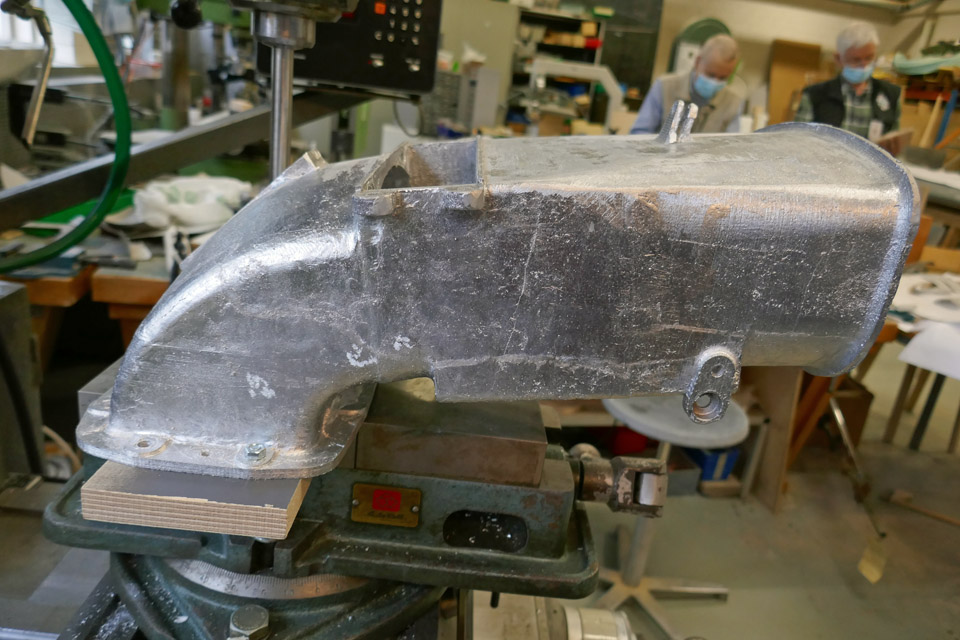
The cast aluminium air horn is now at the Tuesday Club and is ready for further work. Some extra material has been ground off. Holes for fastening bolts will be drilled. The Tuesday Club wishes to thank the SASKY Municipal Education and Training Consortium for preparing the aluminium cast of the air for the restoration the restoration project of the VL Myrsky II (MY-14). Photos: Lassi Karivalo except if otherwise mentioned. Translation: Erja Reinikainen. |
|
Avainsanat: aviation history, restoration, VL Myrsky II, MY-14 |
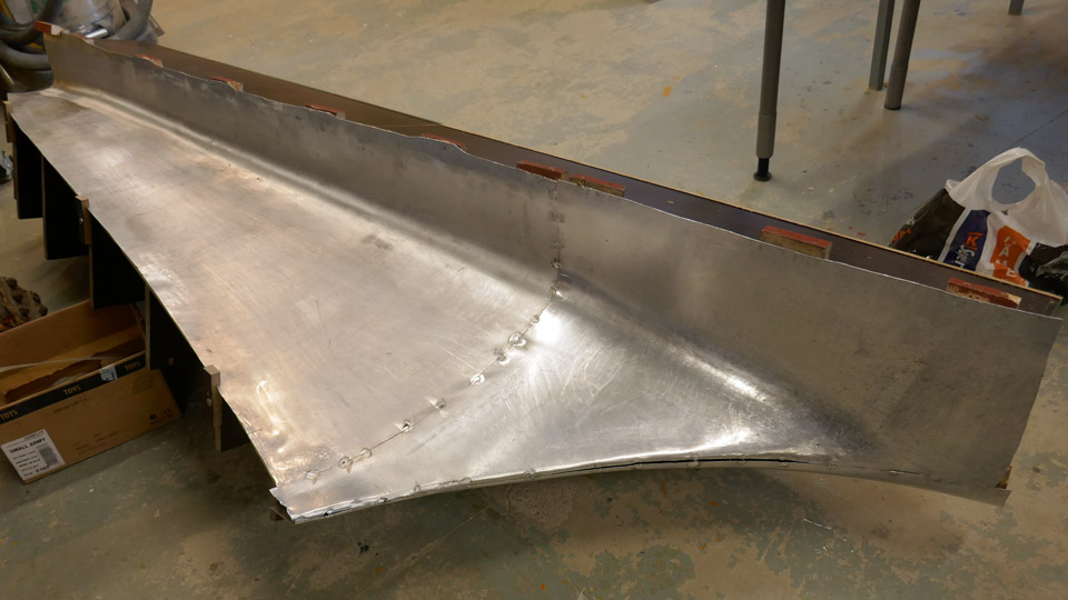
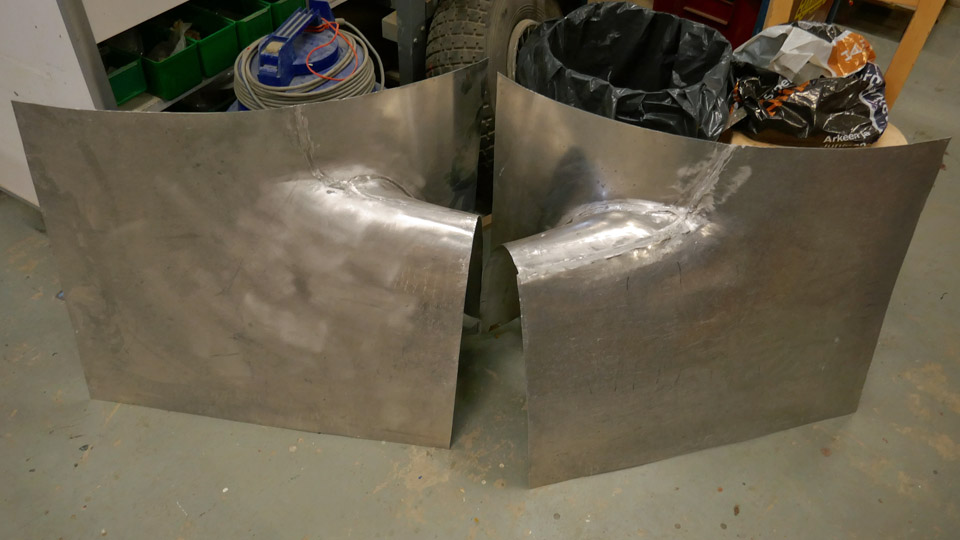
Wing root fairing of Myrsky?s port wing at Tuesday ClubSunnuntai 11.4.2021 - Tuesday Club member The joint of Myrsky-fighter’s (VL Myrsky II) fuselage and wing is covered with a wing root fairing, made of 1 mm thick aluminium sheet. The wing root fairing consists of a short front section, which covers the leading edge of the wing and reaches under the fuselage. The longer rear section of the wing root fairing covers the seam of the fuselage and the wing, all the way to the trailing edge and around it.
The rear section of the port wing root fairing was sent to the Tuesday Club for further modifications. It came from Flanco Oy where Antero Flander had forced it into shape against a mould. The Finnish Air Force Museum, working on Myrsky’s restoration at Tikkakoski, had made the sturdy plywood mould. The wing root fairing was made from three aluminium sheets, forced into shape against the mould and then welded together.
The parts of the port and starboard wing root fairings, which cover the front section of the fuselage and wing joint, had already been sent from Flanco Oy to the Tuesday Club in Vantaa where the parts were welded together. The moulds for the front sections had been made by the Tuesday Club. Flanco Oy has helped in making several other metal parts that are needed in the restoration of the Myrsky MY-14.
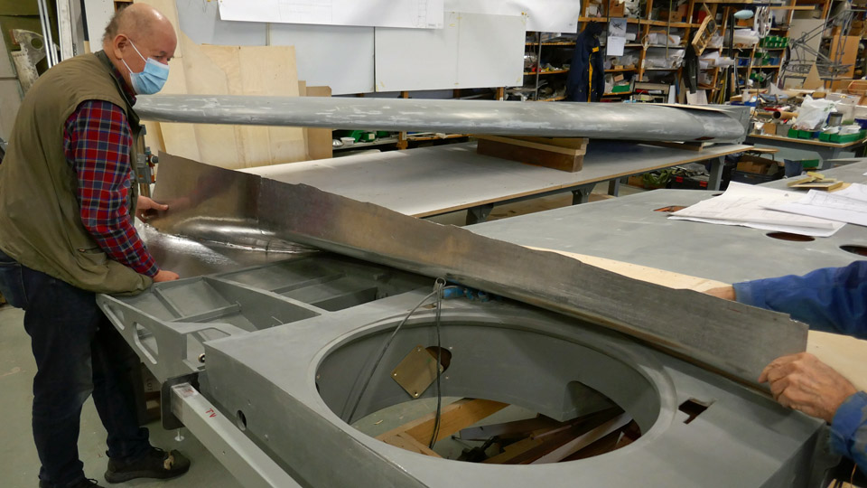
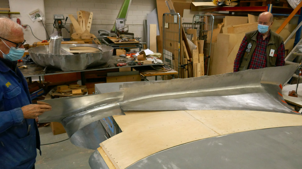
The Tuesday Club team had now both sections of the port wing root fairing and they could be preliminarily fitted into place at the root of the port wing.
The front and rear sections of the wing root fairings will be finalized at the Tuesday Club, joined together and test assembled. The front and rear sections will be joined together with a joint where the aluminium plate riveted on the lower side of the rear section’s front edge is pushed under the front section’s edge. The holes have not yet been made for the flange nuts, which are used for fastening the wing root fairing sections to the side of the fuselage and to the wing surface.
The wing root fairings will be test assembled when the wing halves, made and undercoat painted at the Tuesday Club, will be assembled on the fuselage frame of VL Myrsky MY-5 at the Finnish Aviation Museum. However, it will take some time before the wing root fairings are ready for the test assembly. Photos: Lassi Karivalo Translation: Erjan Reinikainen. |
|
Avainsanat: aviation history, restoration, VL Myrsky, MY-14 |
Wheel well and aileron inspection hatches on Myrsky?s test wingSunnuntai 21.3.2021 - Tuesday Club member When the undercoat painting of VL Myrsky II’s (MY-14) wings and tail part surfaces had been completed, the activity of the six Tuesday Club members working on the Myrsky project could be targeted to other things. The new work item is the test wing and the construction of its wheel well and the installation of the ailerons’ inspection hatch covers.
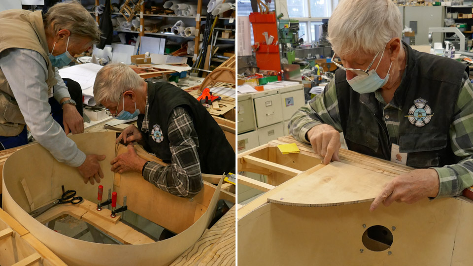
The wheel well of the test wing is in the square space bordered by the front and rear spars and the wing ribs. The wall of the wheel well is made of 2 mm thick plywood. The wall billet had been cut earlier, now it was fitted into place by bending the plywood into a circle, in the space bordered by the spars and ribs. At the fitting stage the plywood wall was too tall for its space. When the wall had settled into place as desired, the excessive height was cut away and the plywood wall was fastened. The next phase was to make from plywood the corner pieces to cover the empty spaces in the corners of the wheel well.
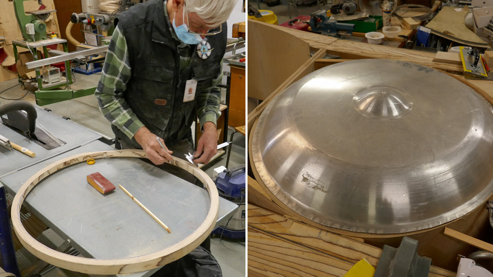
A supporting curb will be built on the upper edge of the plywood wall of the wheel well. The pressure lathed aluminium cover will be fastened on the curb to shield the wheel well. The covers have already been lathed for both wheel wells of the test wing. The supporting curb and the cover on the starboard wing half are already in place. The wheel wells and their covers will be hidden under the aluminium wing root fairings, which cover the seam of the Myrsky’s fuselage and wing.
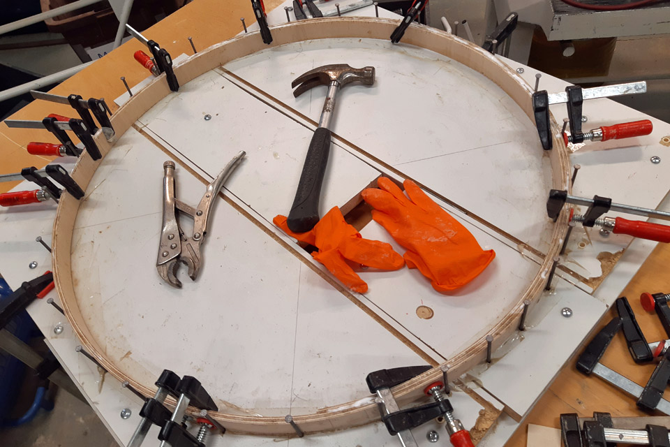
The supporting curb for the wheel well’s upper edge on the port side wing half was made from plywood strips which were glued together and forced into a mould. When the glue had dried, the supporting curb was unfastened from the mould and modified into measure and is now waiting to be installed.
Simultaneously with the building of the wheel well, the fitting of the half-finished aileron inspection hatch covers was started. This task has been waiting while the ailerons were being painted with undercoat paint.
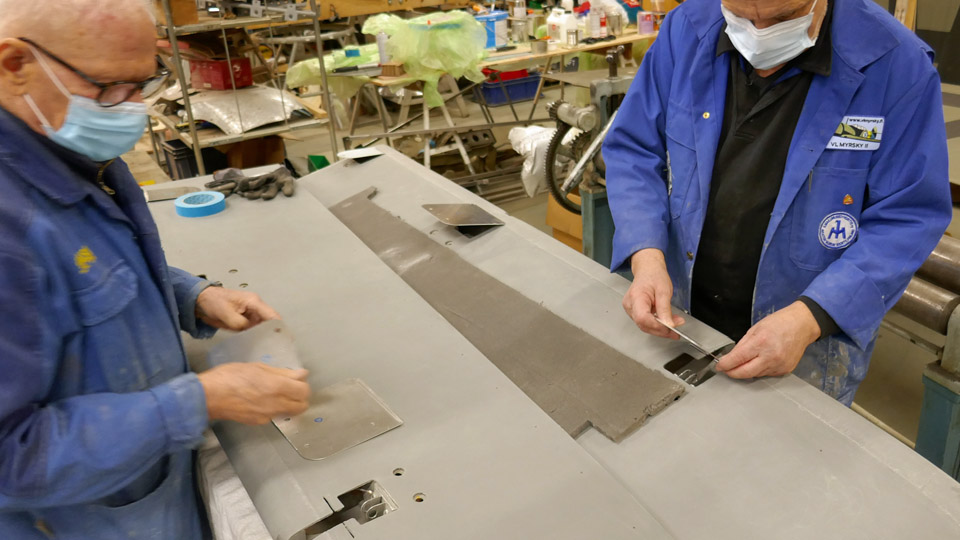
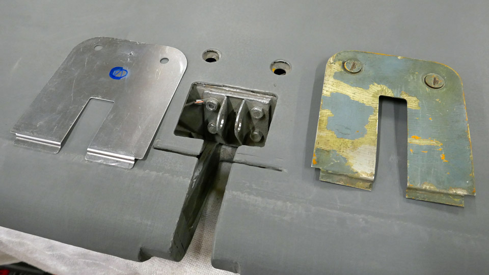
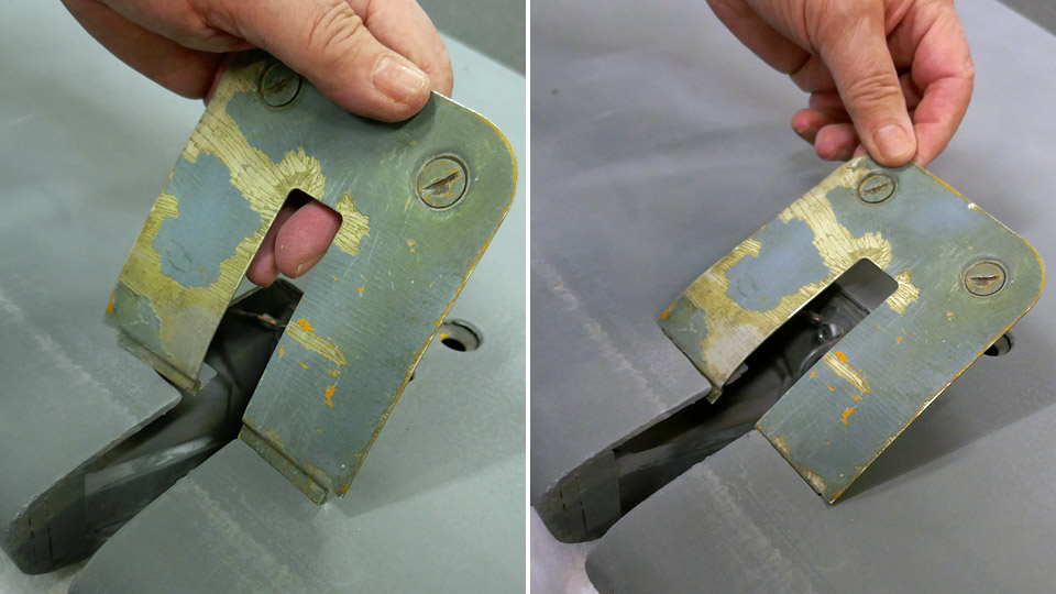
The aileron is fastened on the wing with three hinges. The hinge knuckles inside the aileron’s leading edge are fastened on the journaled hinge arms on the wing with bolts. On the lower side of the aileron’s leading edge there is an inspection hatch for each hinge. The opening of the inspection hatch has a cover made of 1 mm thick aluminium plate. The Tuesday Club team has one original hinge hatch cover as a model. The cover is for the hinge hatch in the middle of the aileron. However, the team made new covers for all aileron inspection hatches. On the front side of each inspection hatch opening there is a slot on the aileron’s surface for fastening the cover.
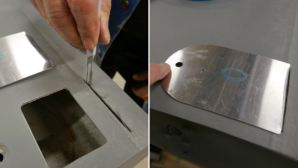
These slots for fastening the inspection hatch covers had been covered during the undercoat painting of the aileron, when a strip of linen fabric was fastened to reinforce the leading edge. The covered slots were cut open with a sharp knife, then the inspection hatch covers were fitted into place, one by one. When the hatch is closed, the front edge of the cover is slipped into the slot in the aileron, then the cover is pressed against the aileron surface to cover the opening. The cover is locked into place with one or two screws, located on the rear edge of the cover. The screws are pressed and locked into the locking holes with springs. The new aluminium hatches don’t have the locking screws yet. Photos: Lassi Karivalo Translation: Erja Reinikainen |
|
Avainsanat: aviation history, restoration, VL Myrsky, MY-14 |
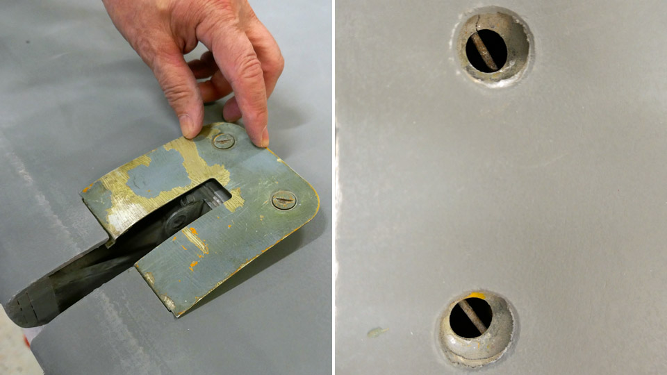
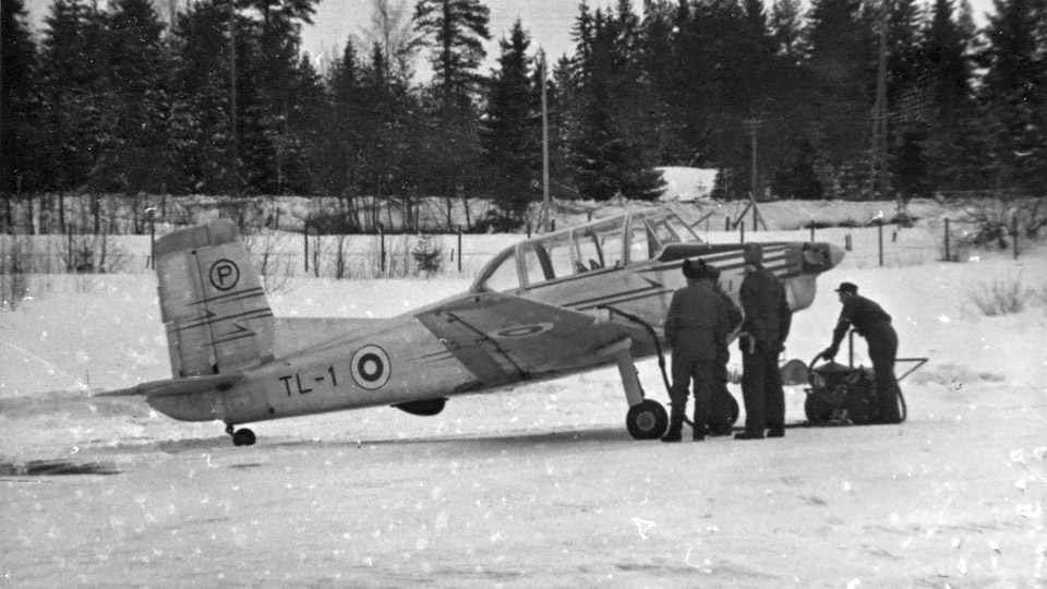
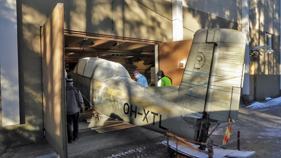
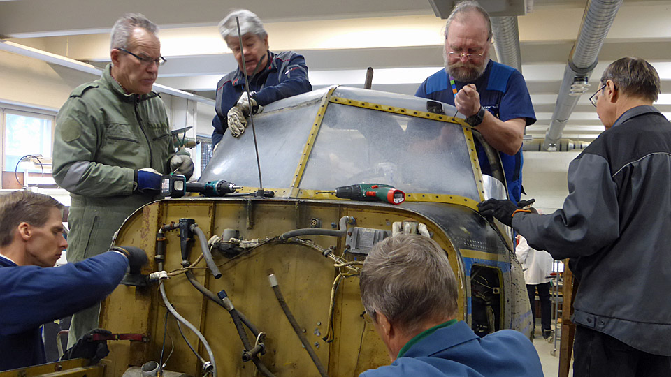
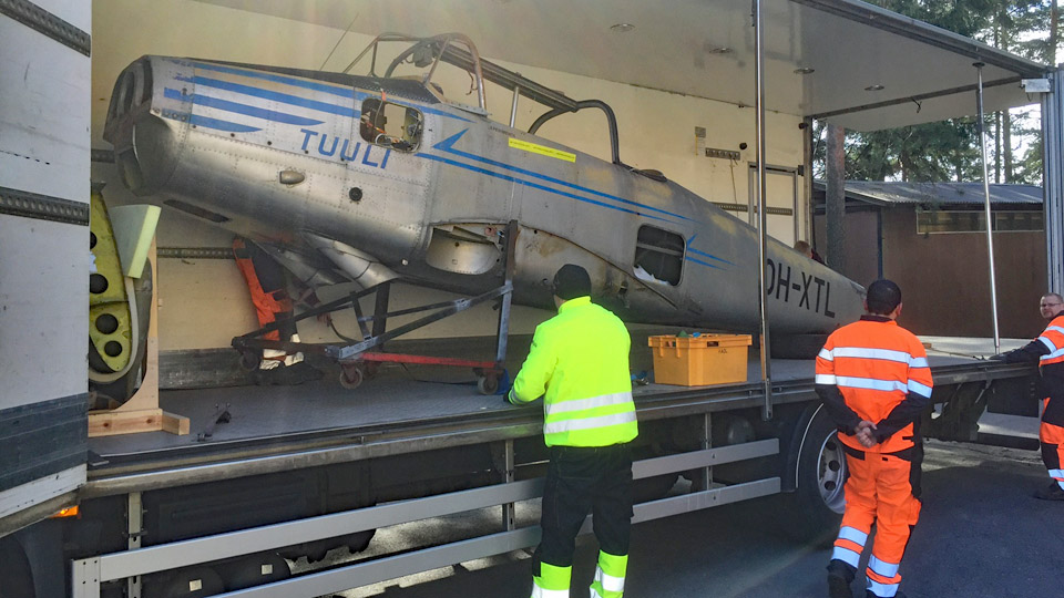
Valmet Tuuli III (TL-1) returned to Finnish Aviation MuseumLauantai 13.3.2021 - Tuesday Club member The restoration of Valmet Tuuli III (TL-1), which remained a prototype, is a joint venture of the Wednesday Club of the Finnish Aviation Museum and the Tuesday Club of the Aviation Museum Society. The restoration project started in 2016. When Tuuli III had been dismantled in the restoration space of the Finnish Aviation Museum, the fuselage, wings and parts of the tail were taken to the Tavastia Vocational College in Hämeenlinna.
Photo: The photo archive of the Finnish Aviation Museum / Kauko Tuomikoski's collection.
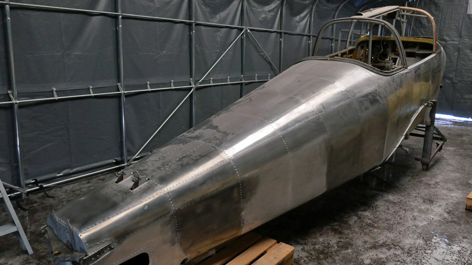
The aim was that the aircraft’s surface treatment is done by the students of the Tavastia Vocational College. This included the cleaning and painting of the surfaces. The work was started by degreasing the tail parts and wing surfaces. After that the silver paint surface was removed with Nitromors paint stripper, dry ice blowing and grinding.
Photo: Antti Laukkanen. The wings and tail parts had already been painted with yellow adhesion primer (acid primer), when it was discovered that the surfaces of Tuuli III had originally been clean aluminium surfaces. Only the belly, the leading edges and some decorative elements had been painted. The aim was to restore Tuuli III into its appearance during the test flight time. This meant that the adhesion primer, which had been sprayed on the wings, had to be removed. The fuselage surfaces had not yet been painted with undercoat paint at the vocational college.
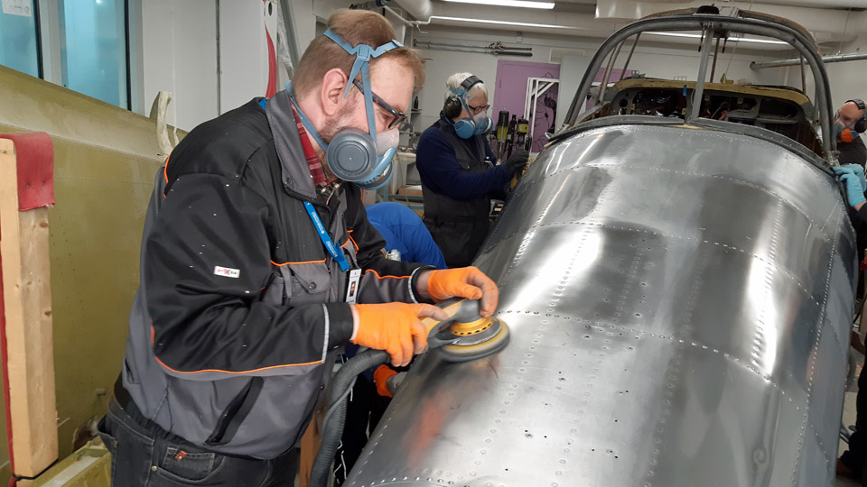
In February 2020 the students of the Tavastia Vocational College attended a surface treatment course at the aviation museum. They learned how to polish aluminium surfaces, using the Tuuli III fuselage as the target. After this the aim was that the Tavastia students continue with the polishing work. However, Tuuli III work was interrupted in Hämeenlinna, because the Vocational College has been mainly remote in education due to the Covid-19 pandemic. Additionally, the space where the Tuuli III has been stored at the vocational college was needed for other purposes. Therefore, it was decided that the Tuuli III is returned to the Finnish Aviation Museum.
When the Covid-19 pandemic situation allows, the volunteer activities at the museum will be started again and the restoration of Tuuli III can be continued. Surface treatment of the fuselage and wings will be the following phase and after that the aircraft will be assembled and the engine restoration continued.
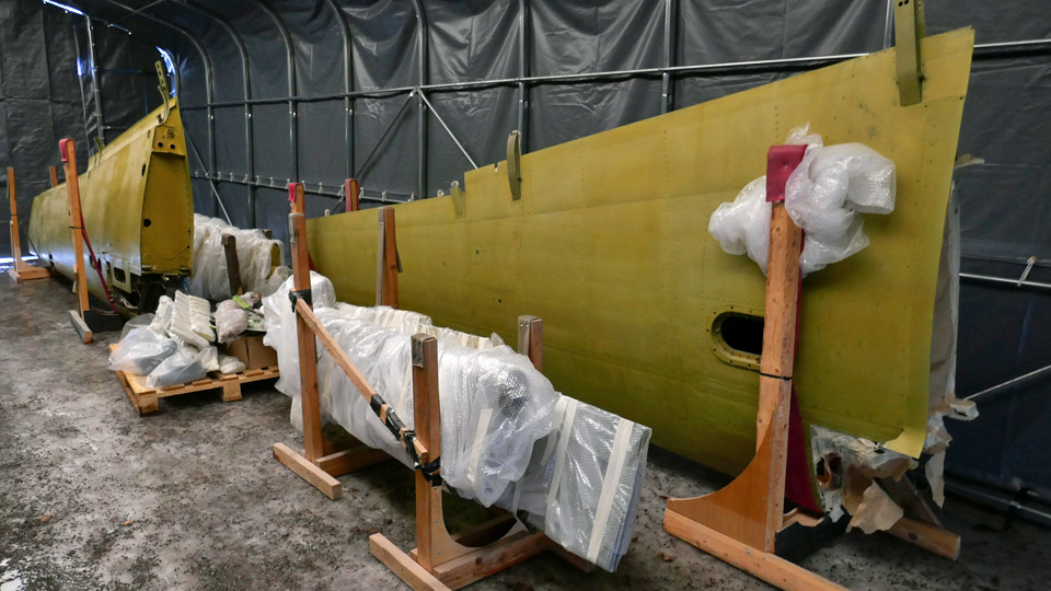
At the moment there is no vacant indoor space in the museum for continuing the restoration of Tuuli III. Due to the Covid-19 pandemic, the restoration work of VL Myrsky II (MY-14) and Caudron C.50 (CA-50) is still unfinished. For now, Valmet Tuuli III is stored at the museum premises in the new storage tent. The restoration work of Tuuli III can be continued in the tent, at least to some extent, during the summer period. Photos: Lassi Karivalo except if separately otherwise mentioned. Translation: Erja Reinikainen. |
|
Avainsanat: aviation history, restoration, Valmet Tuuli III, OH-XTL, TL-1 |
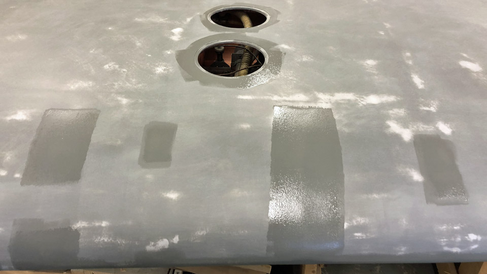
Undercoat painting of Myrsky?s wings was finishedLauantai 27.2.2021 - Tuesday Club member The undercoat painting of the upper sides of Myrsky’s (VL Myrsky II, MY-14) wing halves took about two months. Now the work is ready. The undercoat painting procedure of the upper sides followed the undercoat painting of the lower sides of the wings. First the plywood surfaces are painted with pale grey TEMALAC AB 70 alkyd paint which contains aluminium flakes, and it is covered with a couple of layers of dark grey Teknos Oy adhesion primer Futura 3.
Photo: Jouni Ripatti. The painting of the upper surfaces of the wing halves with aluminium flake undercoat paint was described in the previous blog. Before the dark grey adhesion primer could be applied on the aluminium flake undercoat paint, the painted surface was ground smooth and some uneven spots on the plywood surface had to be spackled.
Photo: Jukka Köresaar.
The Teknos Oy's Futura 3 RAL 7005 adhesion primer was spread with a mohair roller. When the paint had dried, it was noticed that the painted surface wasn’t as smooth as it should have been. Some uneven “orange peel surface” was detected. The painted surface was therefore ground smooth manually and with a disk grinder, using 180 sandpaper grit.
Photos: Jouni Ripatti. The paint dust was removed and a new layer of Futura 3 paint was applied. This time the paint was thinned with white spirit to a solution of 80%. The soft mohair roller was changed into a harder foam rubber roller. This time the result was satisfactory, but in some places some uneven paint surface could still be seen. However, after grinding the Futura 3 undercoat paint surface was very smooth.
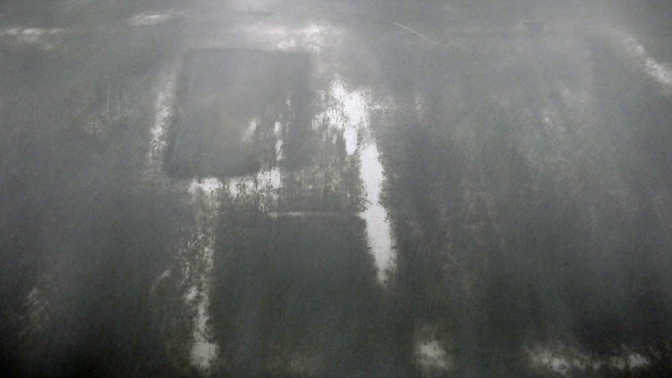
Photo: Jouni Ripatti. When the small uneven areas were ground, the paler grey aluminium flake paint was revealed from under the darker adhesion primer and the surface looked patchy. It is important, that the two undercoat paints have different shades. Because of this it can be seen when the lighter grey layer of alkyd paint becomes visible when the top layer of the adhesion primer surface is ground.
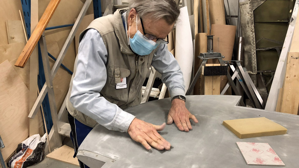
When using the disk grinder to grind the Futura 3 surface, the bare plywood surface appeared in some places. This was not the purpose. These places were patched with a layer of adhesion primer. When the patched spots had dried they were ground manually, using first a rougher (150) INDASA Fine sanding pad and then a finer (240) INDASA Super Fine sanding pads.
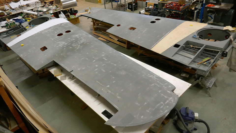
Now the upper and lower sides of the MY-14 wing halves have been painted with undercoat paint and they are waiting for the paint finishing. The upper surface will be dark green with black camouflage and the lower side will be DN-blue. The paint finishing will not be done at the Tuesday Club, it will be bought from outside. The main reason for this is that the restoration space of the Finnish Aviation Museum is not sufficiently dustless or suitable for the large-scale spray painting of the wing surfaces.
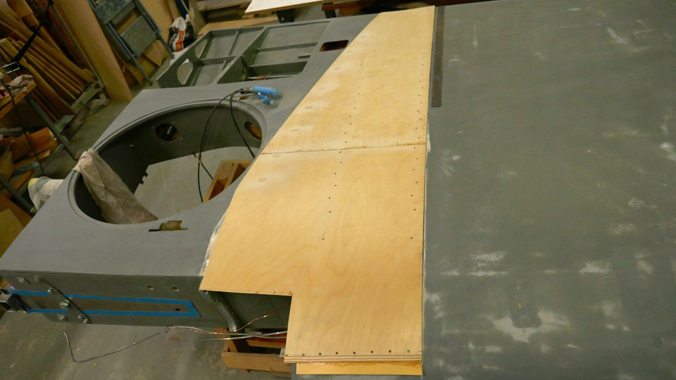
The Tuesday Club team can now continue with the other remaining work in the construction of the Myrsky’s wing. The installation of the step plates on the upper surface of the wing root has been started. The step plates have been cut from 2 mm thick plywood and they haven’t been painted yet. The aluminium wing root fairings, which protect the seam of the fuselage and the wing, are fastened on the inner edge of the step plates. Photos: Lassi Karivalo except if otherwise separately mentioned. Translation: Erja Reinikainen |
|
Avainsanat: aviation history, restoration, VL Myrsky, MY-14 |
Plywood surfaces of upper sides of Myrskys wings are ground and painted with undercoat paintLauantai 6.2.2021 - Tuesday Club member When the lower sides of VL Myrsky II’s (MY-14) wings had been painted at the Tuesday Club with undercoat paint, the wings were turned around and the undercoat painting of the upper sides was started. The procedure follows the undercoat painting of the lower sides of the wings. First the plywood surfaces are painted with Tikkurila Oy pale grey TEMALAC AB 70 alkyd paint which contains aluminium flakes, using fine rollers. The flake paint is used to make the plywood surface very smooth. The aluminium flake alkyd paint is covered with a layer of TEKNOS Oy adhesion primer Futura 3. The wing surfaces are painted with several layers of both paint types and after each layer the surface is ground smooth with sandpaper. The adhesion primer has a darker shade of grey than the alkyd paint, so that it can be seen when the lighter grey layer of alkyd paint becomes visible when the adhesion primer surface is honed.
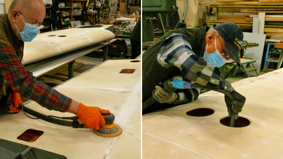
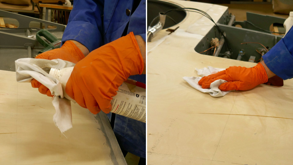
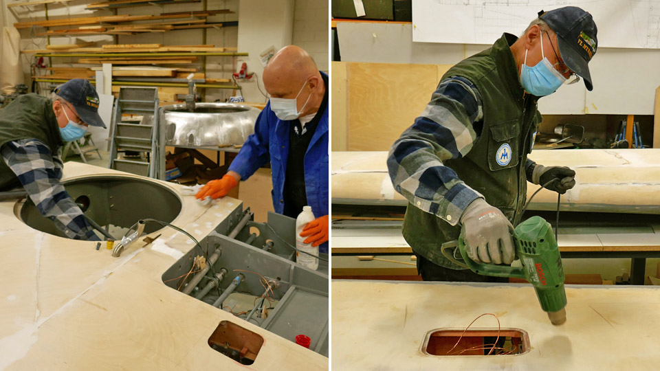
Before starting with the aluminium flake alkyd paint, a couple of plywood seams were spackled on the upper side of the wing. Then the plywood surfaces were ground as smooth as possible. A disk grinder was used, with 180 grinding paper grit. The disk grinder also removed the grinding dust. After this the plywood surfaces were vacuumed and wiped with an alcohol solution which removes grease. The solution contained 50% Sinol and 50% water. Then the damp surfaces were dried with a heat blower. Then the grinding was repeated, now manually and using 240 sandpaper grit. Then the surfaces were cleaned again.
Photo: Jouni Ripatti.
Photo: Jouni Ripatti.
Photo: Jouni Ripatti.
Photo: Jouni Ripatti. The aluminium flake alkyd paint was applied on the upper sides of the Myrsky’s wings with mohair rollers. In spite of this the paint surface quality wasn’t acceptable – it had some uneven “orange peel surface” parts. Therefore the first layer of paint was carefully manually ground smooth. The surfaces were painted again, this time with aluminium flake paint, thinned to 80%. This is how the desired quality of the painted surface was reached. The upper sides of the wings will be painted with another layer of TEMALAC aluminium flake undercoat paint before the Teknos Futura 3 adhesive primer is applied. Photos: Lassi Karivalo except when separately otherwise mentioned. Translation: Erja Reinikainen. |
|
Avainsanat: aviation history, restoration, VL Myrsky, MY-14 |
Myrsky restoration continues after Christmas breakPerjantai 29.1.2021 - Tuesday Club member Since mid-January the Tuesday Club team has been working again in the restoration space of the Finnish Aviation Museum, continuing the restoration of Myrsky after the Christmas break. Other Tuesday Club activity is still on a break due to the Covid-19 pandemic. Myrsky restoration is continued by only half a dozen club members, taking all Covid-19 restrictions and recommendations into account.
Lower photo: Jouni Ripatti. The lower sides of Myrsky’s wings were painted with another layer of the grey adhesion primer and then it was time to begin with the undercoat painting of the upper side of the wing. Before the wings were turned, excessive paint was scraped from the edges of the inspection hatches on the lower side of the wing. This allows the aluminium hatch doors to sink properly into their openings and to the level of the plywood surface. Some rather awkward working positions were needed in this phase.
When the undercoat painting of the lower sides had been finished, the Tuesday Club started the preparations for turning the wings so that the upper sides can be painted. Steel tube lifting frames had been made to be fastened on the wing tip and wing root when the wing is turned. The frames have a shaft extension for fastening the lifting slings.
Tip: move your mouse on the photo!
The lifting slings were fastened on the frames and one wing at the time was lifted from the worktable with a stacker and a lifter and turned around. Now the unpainted wing surface was facing upward. The wing was place back on the worktable and the lifting frames at the ends of the wing were unfastened. Now all preparations have been made and the undercoat painting of the upper side of the wings can be started. Photos: Lassi Karivalo except when separately otherwise mentioned Translation: Erja Reinikainen |
|
Avainsanat: aviation history, restoration, VL Myrsky, MY-14 |
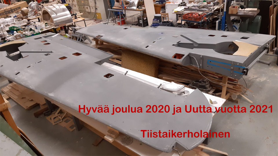
Myrsky project goes on Christmas breakKeskiviikko 23.12.2020 - Tuesday Club member
Merry Christmas 2020 and New Year 2021! The Tuesday Club Member. The hammering and tinkling of the Myrsky project have stopped in the restoration space of the Finnish Aviation Museum. It is time to have a break and rest over Christmas. We will be back at work on January 5th. Because of the coronavirus pandemic this year has been very exceptional for the Tuesday Club. Naturally it has also been exceptional for Finland and for the whole world. In March we had to terminate all our activities. Since June it has been possible to continue the restoration of VL Myrsky II (MY-14), but with only a handful of club members working at a time. The restoration of the Caudron C.50 aircraft and the reparation of the PZL SM-1SZ helicopter blades have been on a break all the time. In spite of the small task force, a lot has been accomplished in the Myrsky restoration work. The Myrsky’s wing structures have been completed and now the lower sides of the wings have been painted with undercoat paint. After the Christmas break the undercoat painting will continue on the upper sides of the wings. The Tuesday Club team has worked in close co-operation with the Finnish Aviation Museum and the Finnish Air Force Museum. I hope sincerely that the coronavirus pandemic will be blocked next year and the whole Tuesday Club team can return to work at the Finnish Aviation Museum. Hopefully in the autumn 2021, at the latest, it will be possible to continue the restoration work on the historically valuable aircraft with the full task force. We wish you a peaceful Christmas time and a better New Year 2021! Photo: Lassi Karivalo. Translation: Erja Reinikainen. |
|
Avainsanat: aviation history, restoration, VL Myrsky, MY-14, MY-5 |

Ilmailumuseot.fi - Aviationmuseums.fi