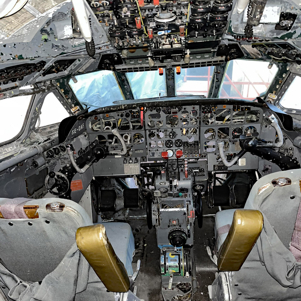
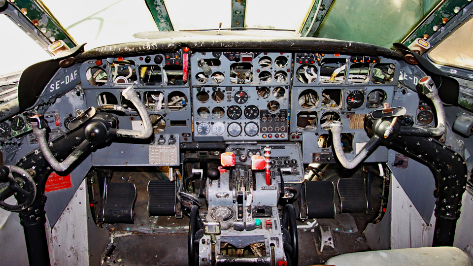
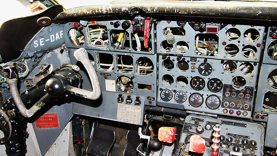
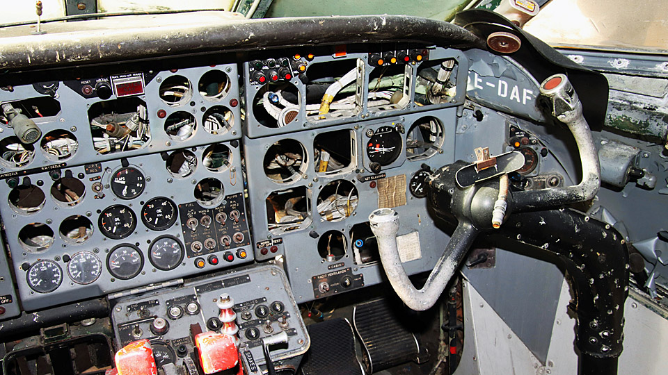
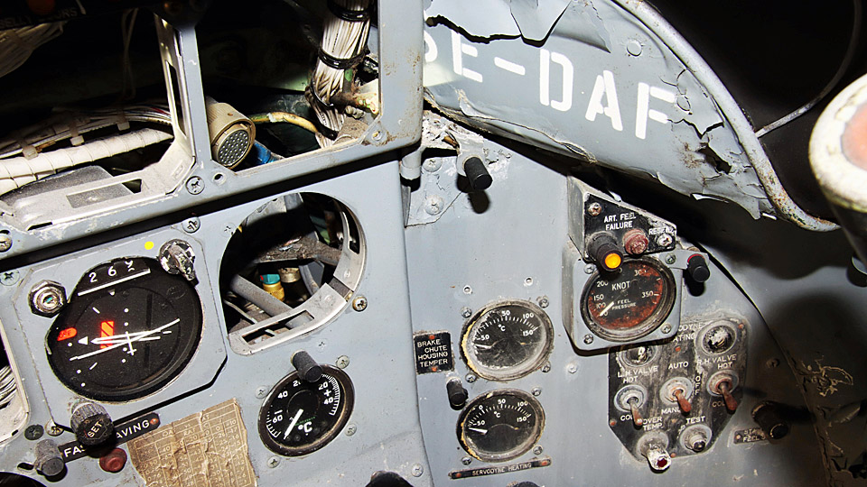
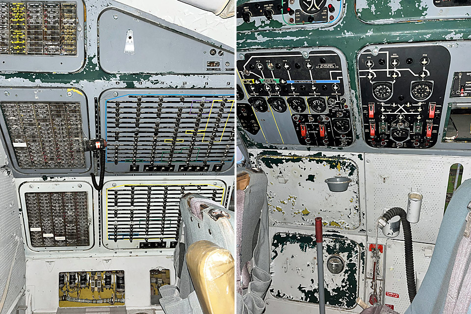
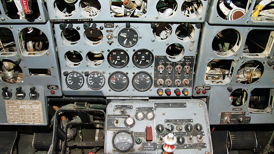
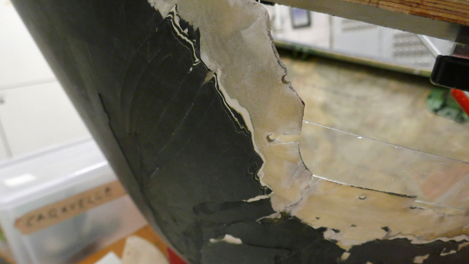
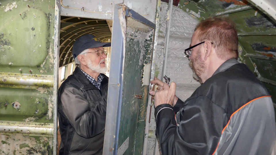
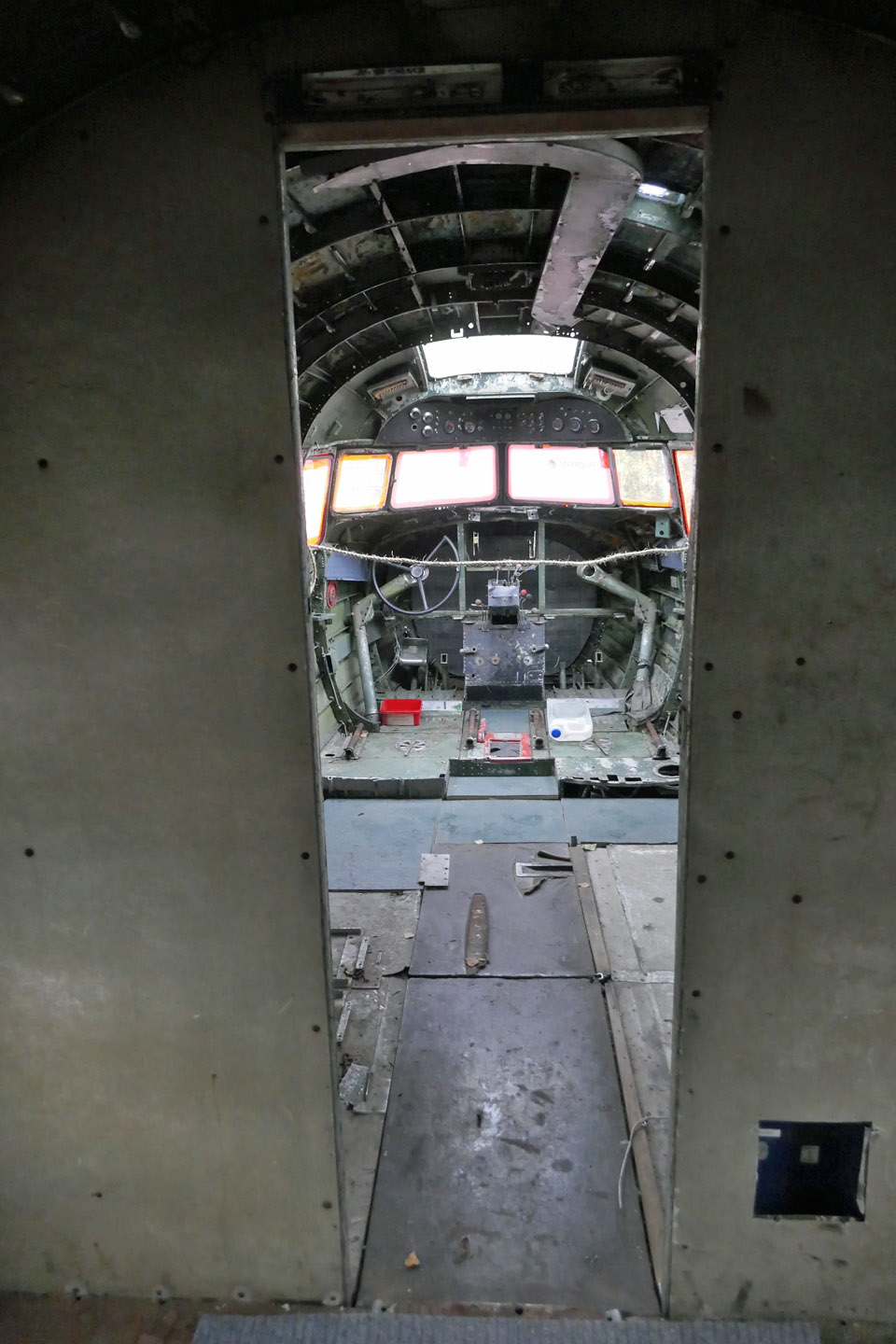
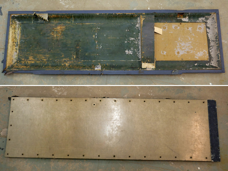
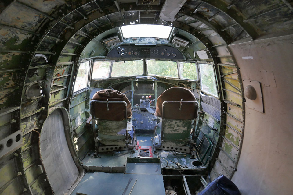
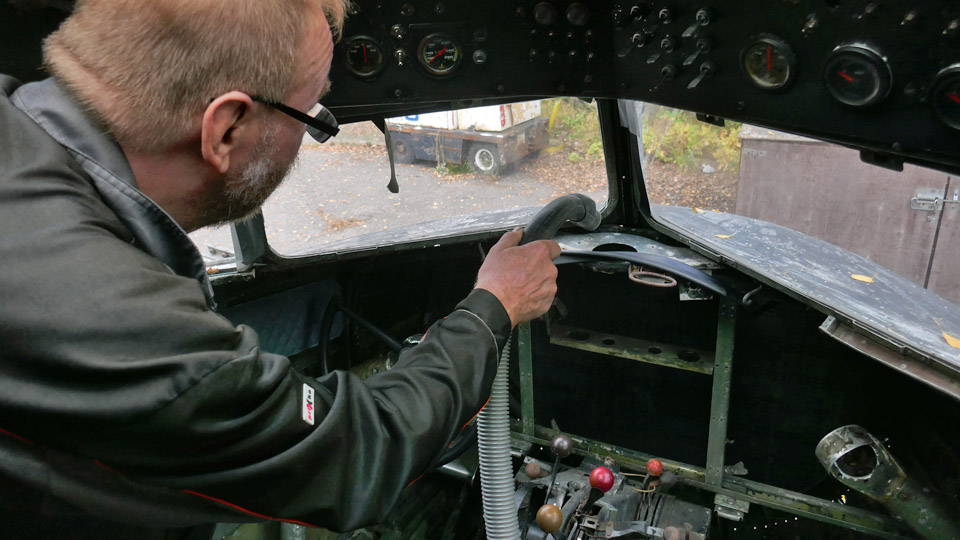
The Caravelle's cockpit is missing instruments and equipmentKeskiviikko 1.3.2023 - Erja Reinikainen At the moment, the Caravelle SE-DAF’s cockpit looks rather bare and stark. There are a lot of instruments missing and the surfaces and fittings are shabby. The decades of being stored outdoors at Arlanda have left their mark.
Photo by Ismo Matinlauri. We will not let this discourage us, instead we take this as a challenge. Our aim is to find the missing instruments and equipment and restore the cockpit and its surfaces as well as we can.
Now we are looking for analogue instruments which were used in the 1960s’ and 1970s’ aircraft and we turn to our readers for help. The instruments don’t have to be original ones which were used in the Caravelles, a similar style is sufficient. A list of the missing instruments is below, we need two of each. Flight monitoring instrumentsThe size of the flight monitoring instruments varies. Some have a rectangular housing 82 x 82 mm, others a round housing with a diameter of 80 mm. The housing for the Flight Director Indicator / Attitude indicator is rectangular 100 x 100 mm. A round instrument can be installed instead, using a reducer plate.
Engine monitoring instrumentsThe engine monitoring instruments have a diameter of 49 mm. A different size can be used but will be difficult. Instruments with the original displays will probably not be found but the dial face can be changed. The following instruments are missing.
Photos by Ismo Matinlauri.
Radio control panelsThe following items are missing:
If you happen to know anything about the items listed above or if you know where they could be found, please contact Caravelle project manager Janne Salonen, mobile +358 50 5291135 or email janne.salonen@imy.fi Translation with help of Martti Saarinen. Photos by Jouko Tarponen except if otherwise separately mentioned. |
|
Avainsanat: aviation history, restoration, Caravelle, SE-DAF, Sven Viking |
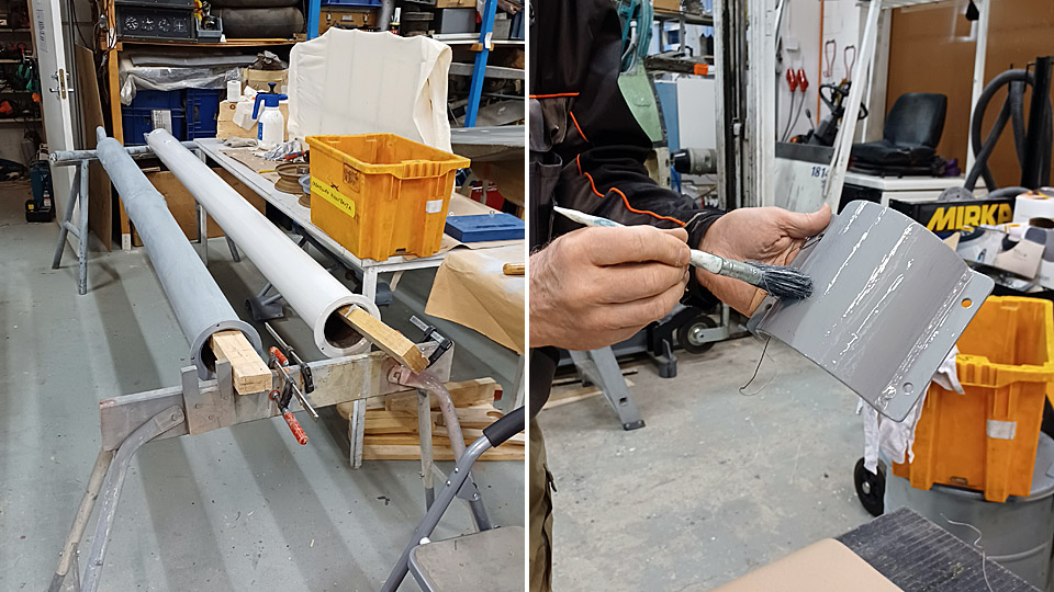
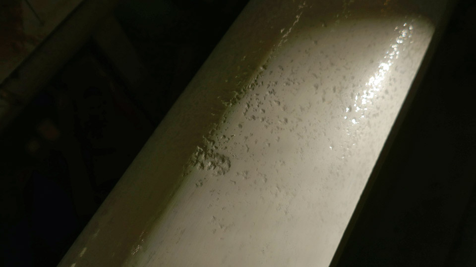
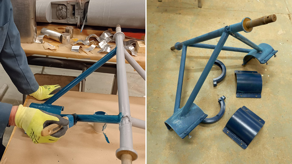
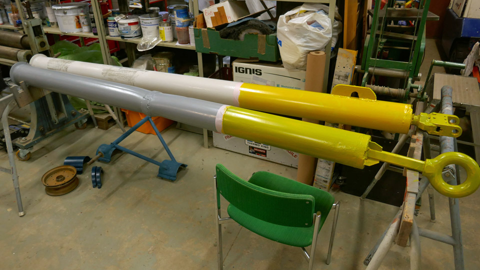
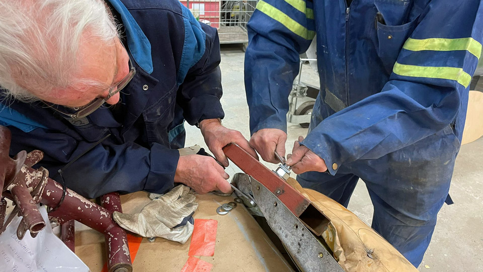
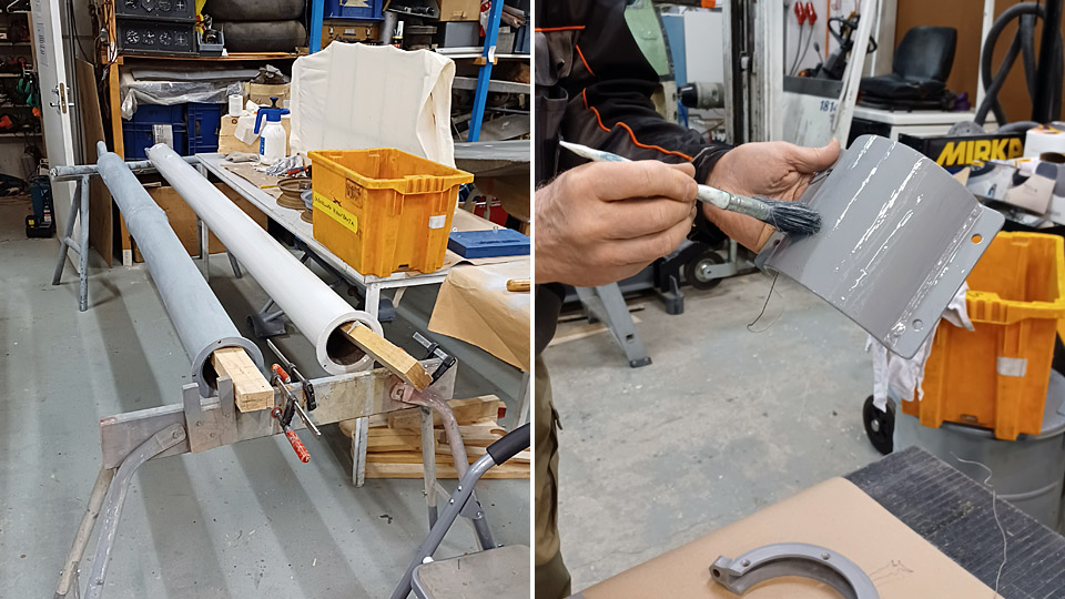
The restoration of the Caravelle III towbar is progressingKeskiviikko 1.3.2023 - Tuesday Club member During Tuesday Club’s autumn season the Caravelle III towbar restoration work reached the point where the majority of the towbar parts had been painted with Isotrol primer, which prevents rusting. Half of them were painted with dark grey Isotrol and the other half with pale grey. We could see that the paint made the corrosion marks on the towbar surface clearly visible.
Photos by Juha Veijalainen.
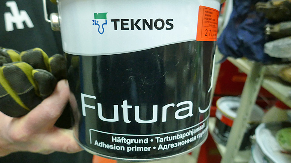
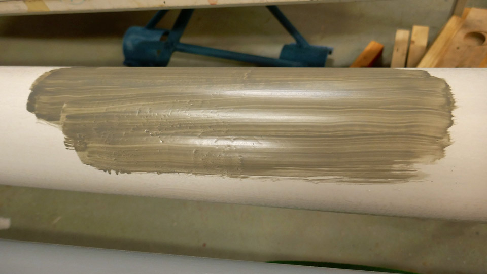
We made a test where a small area of the towbar was painted with Teknos adhesive primer to see whether it would cover the corrosion. It did, indeed, but the corrosion marks were still visible. The next step would have been to spackle the whole towbar to make the corrosion marks disappear. However, we decided not to. We shall let the corrosion spots show and prove that the Caravelle III towbar has been rusting under the open sky for fifty years at Arlanda airport.
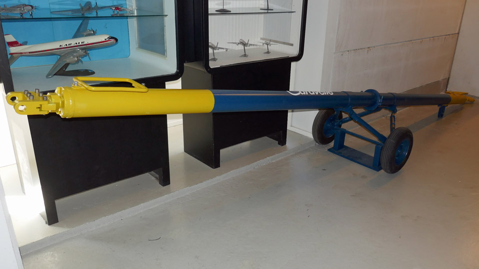
The towbar will be painted to the same paint scheme we used for the Finnair Super Caravelle towbar when it was restored last year. Just to refresh your memory, the towbar now under restoration was brought from Sweden together with the Sud Aviation Caravelle III (SE-DAF), which was acquired by Aviation Museum Society Finland. This towbar has been used by SAS, but we will restore it to Finnair colours. After restoration the towbar will be placed on display at Turku airport together with the Caravelle III, which will be restored to the Finnair 1963 paint scheme as OH-LEA “Sinilintu” (Bluebird).
The main colour on the towbar is the Finnair blue, with 50 cm of the towbar’s pull loop end and 73 cm of the aircraft towhead end painted yellow. The blue paint is Unica outdoor furniture paint NSC S 6030-B and the blue paint Unica outdoor furniture paint RAL 1023.
Photos by Juha Veijalainen.
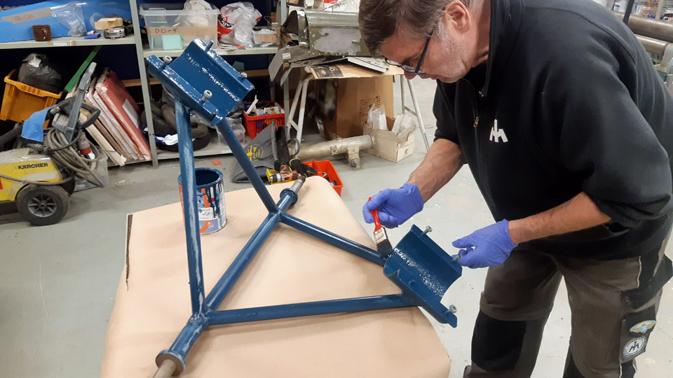
The top coat painting was started from the smaller parts of the towbar. The towbar wheel rack with its fastening flange was the first part to be painted blue. The paint was applied with brushes. After the first layer we noticed that the covering wasn’t sufficient yet. The surfaces were sanded manually with sandpaper and painted with another layer of blue paint. The result was fairly good. We don’t think the wheel rack needs to be painted a third time.
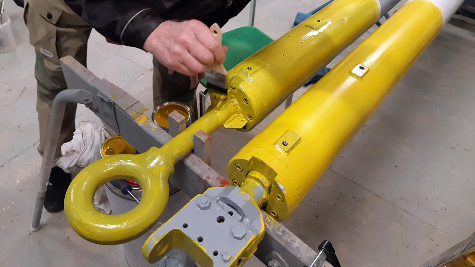
The bar section of the towbar had been dismantled into two parts. The painting with finishing paint was started with the yellow paint. It was soon noticed that already the first layer of yellow paint covered well the bar which had been painted with pale grey Isotrol primer. However, the yellow paint didn’t cover so well the other half of the bar which had been painted with dark grey Isotrol. It would have been better if both halves of the bar had been painted with the pale grey primer. Well, this means only that we will have to apply several yellow layers on the half which was painted with the dark grey. At this point two layers of yellow paint have been applied.
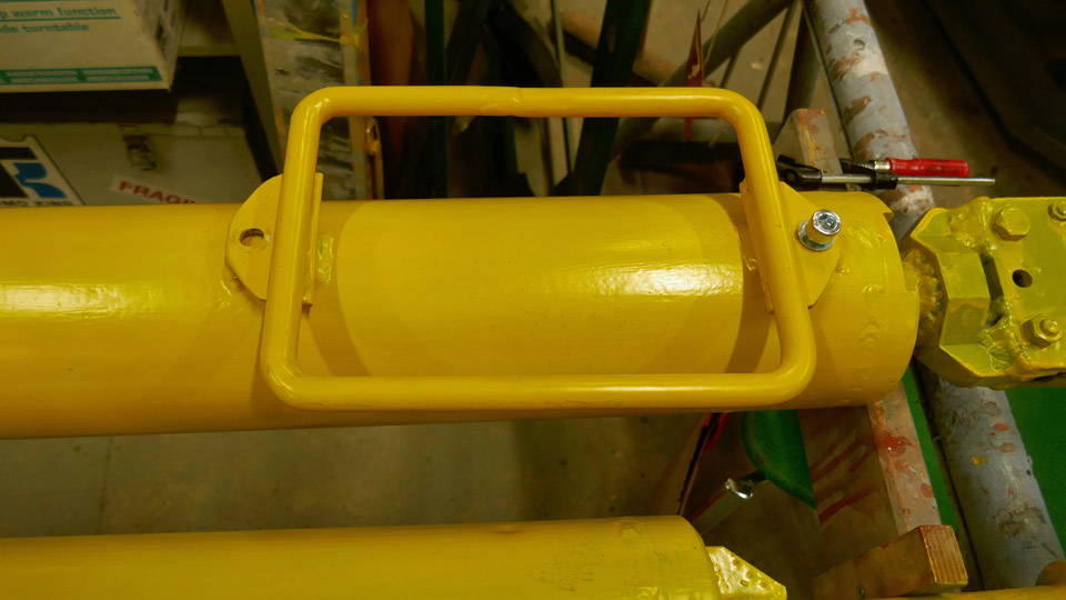
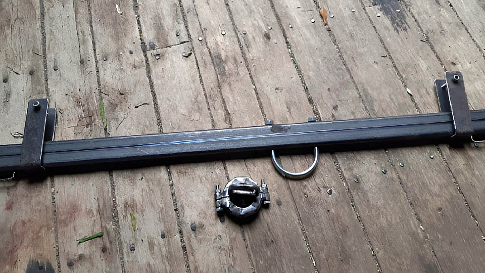
In addition to painting, also other restoration work has been done. Both ends of the towbar lack the rectangular handlebars made of round metal rods. The Super Caravelle towbar we restored earlier has similar handlebars. We unfastened one of them to use it as a model when building the missing handlebars for the Caravelle III towbar. This Caravelle III towbar is the first version of the towbars manufactured by Sud Aviation, its model number is S.09.107 and the Super Caravelle towbar we restored last year is the factory’s last and third towbar version with model number S.09.107 2.
First we started making the fastening plates for the handlebars, using the Super Caravelle towbar handle as a model. There is a fastener plate welded to both ends of the handlebar. There is a 10 mm hole in the plate for a bolt, which fastens the handle on the towbar.
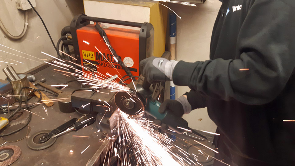
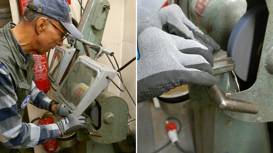
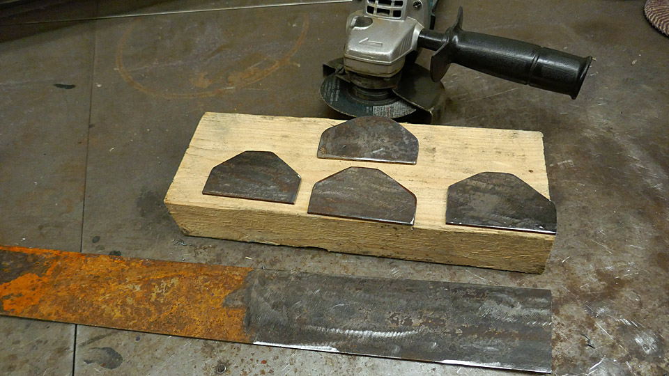
We found a suitable piece of 4 mm thick and 10 cm wide flat bar iron in the metal storage of the Finnish Aviation Museum’s hot work container. Rust was sanded off the flat bar iron and then four 8 cm pieces were cut from it with an angle grinder. The shape of the Super Caravelle towbar handle fastener was drawn on all of them. The extra material was cut off and their corners and edges were shaped round using an emery and an abrasive band. The fastener plates are now ready to be welded on the handlebar, but the holes for the bolts are missing. The following phase will be to make the actual handles for the handlebars.
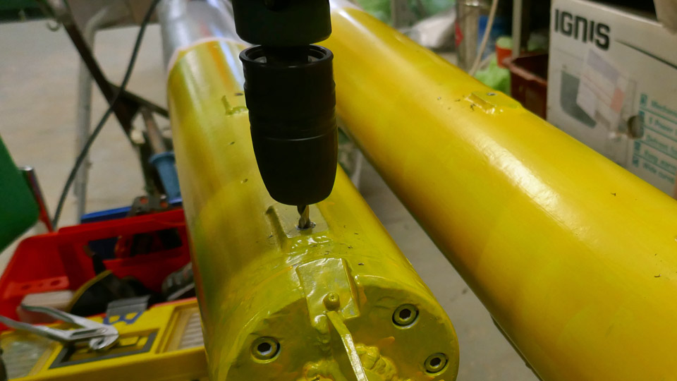
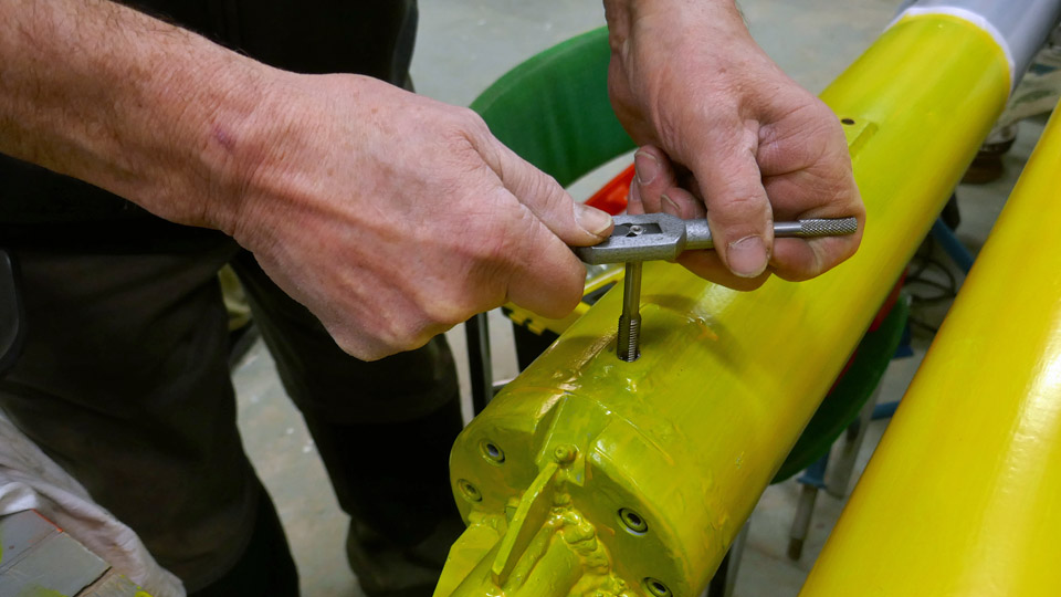
On the surface of the Caravelle III towbar there are the remains of the broken handlebar fastening bolts. The bolts were drilled out, first using an 8 mm drill bit. Then a hole was made for a M10 bolt using a larger drill bit. A thread was made into the hole for a 10 mm hexagon head bolt, using a threading tap. The bolt holes are now ready for fastening the handlebars on the towbar. Translation by Erja Reinikainen. Photos by Lassi Karivalo except if othewise separately mentioned. |
|
Avainsanat: aviation history, restoration, Caravelle, SE-DAF, Sven Viking, Tuesday Club |
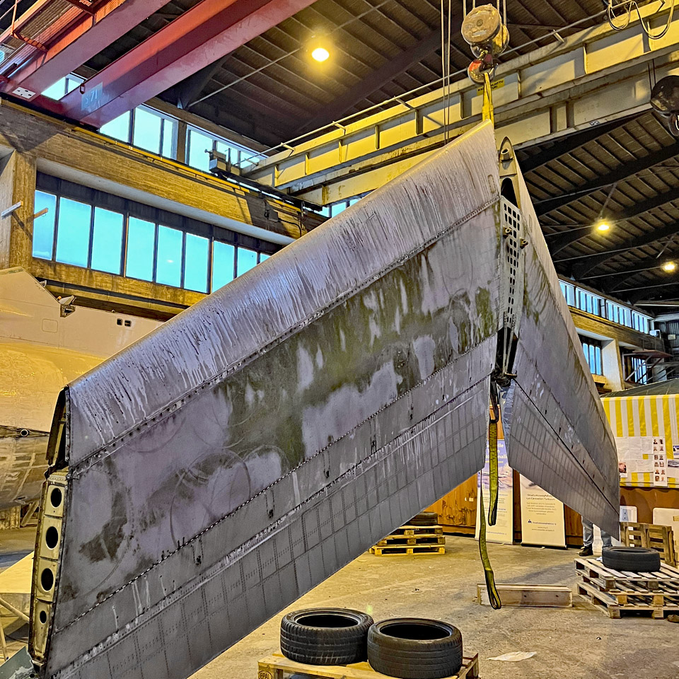
Caravelle restoration - a Week of LiftsLauantai 4.2.2023 - Ismo Matinlauri During last week we performed several lifts using the bridge cranes in the hall where the Caravelle III (SE-DAF) is under restoration. First we turned around the horizontal stabilizer and then we installed the left side engine nacelle. Finally we lifted the rudder to the working area.
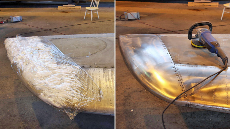
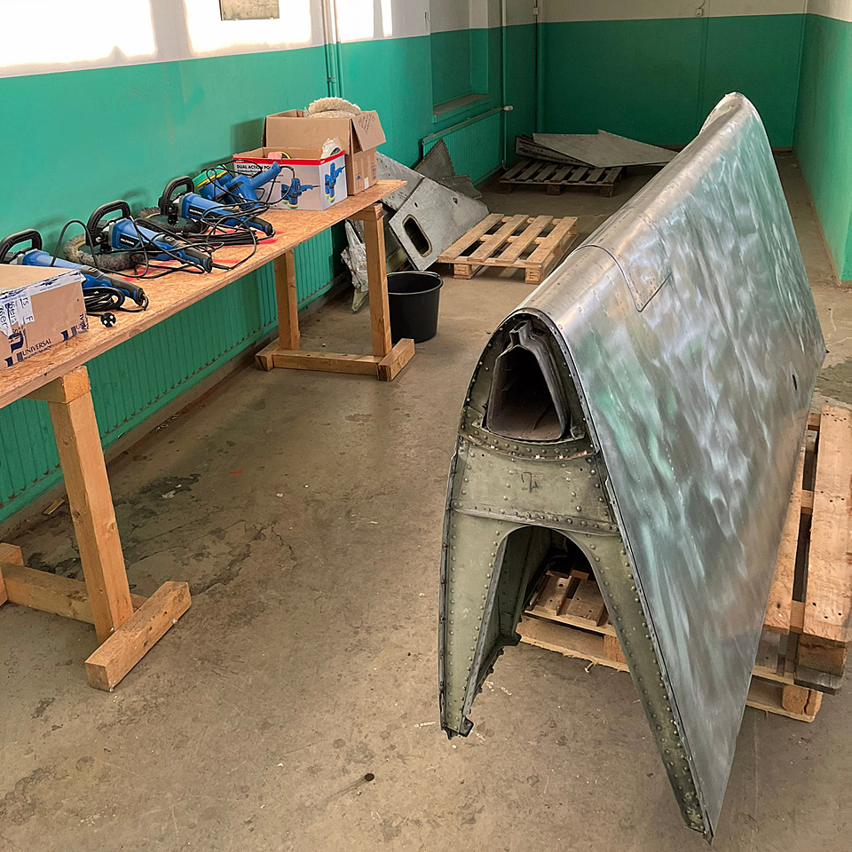
The horizontal stabilizer was turned around because we completed the grinding work on the upper side, and it is now waiting for the temperature to rise to a level where polishing and painting is possible. After the turn we can now do the same work phases to the lower side as well. Then we will polish and paint it before the next lift and turn, after which we can polish and paint the upper side. Then the horizontal stabilizer is ready and the right side up for the installation work.
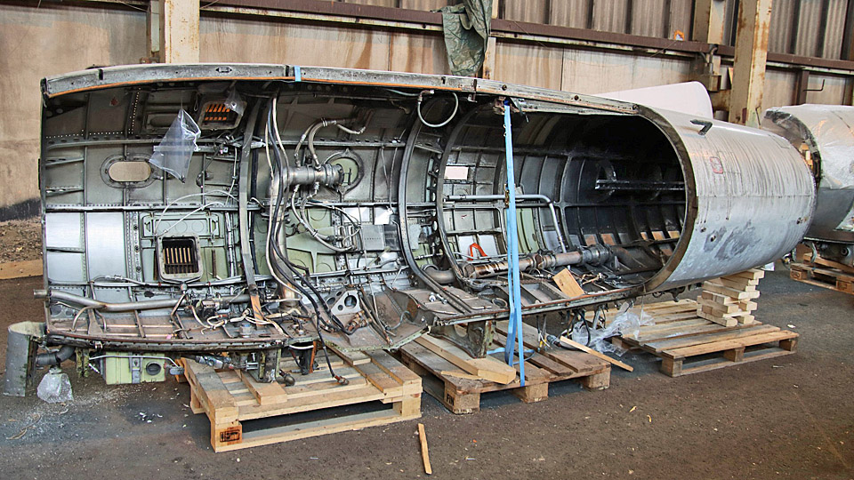
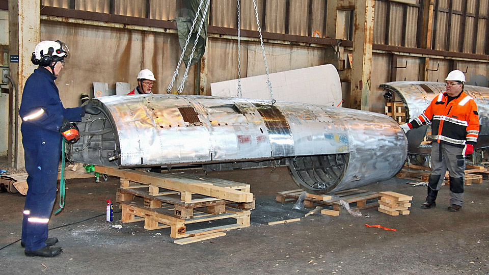
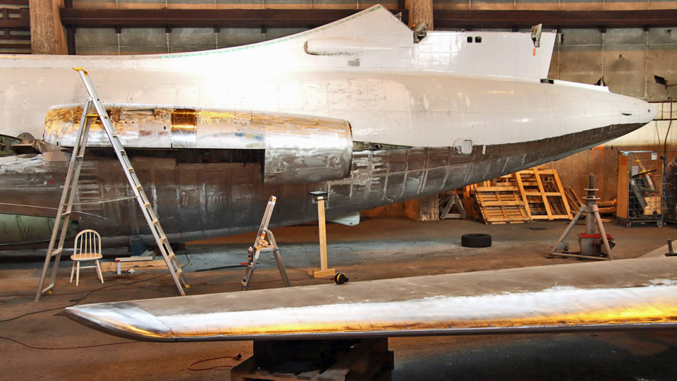
The engine nacelle required some sheet metal work before it could be installed. Some corroded plates needed to be changed or repaired. Time was also needed to fix some screw holes on the fuselage so that they would be ready when the nacelle was in place and the fairings are assembled into place. Finally the nacelles were ground on the outside, now they are ready for painting. Then everything was ready for the nacelle lift.
The left side engine nacelle was lifted back to its place under the supervision of Markku Ahokoski. We used lifting chains tailored for the purpose and connected to the original lifting holes on the nacelle. Fitting and tightening the nacelle’s four fastening bolts took more time than estimated but with some adjustments we managed to do it.
It has been decided that the engine nacelles will be painted with silver colour paint and not polished. This is because the surfaces are worn and there are marks of use. Polishing would lead to an uneven surface and would not look right. The other engine nacelle will be lifted to its place in about two weeks’ time, when the same preparation work as with first one has been completed. Photos by Jouko Tarponen Translation by Erja Reinikainen |
|
Avainsanat: aviation history, restoration, Caravelle, SE-DAF |
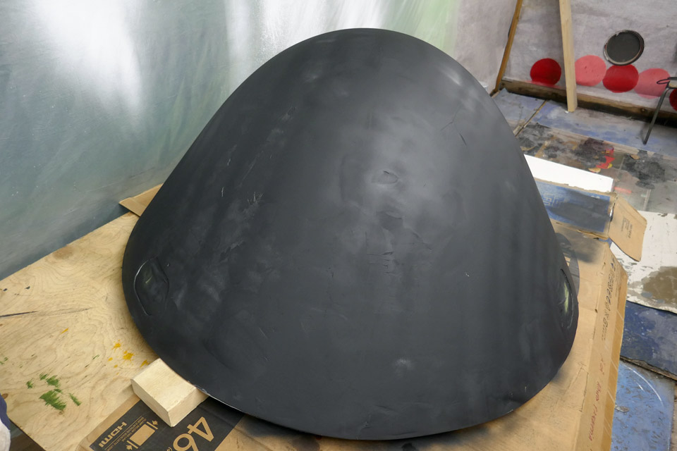
The repairs of the Caravelle radome are almost finishedLauantai 4.2.2023 - Tuesday Club member The repairs of the damaged parts of the Caravelle III (SE-DAF), which was brought to Finland from Sweden, have been continued at the Aviation Museum Society Finland’s Tuesday Club. The repairs of the radome, the bulkhead rim under the radome, the wing tips and the tip of the starboard side horizontal stabilizer are all under way.
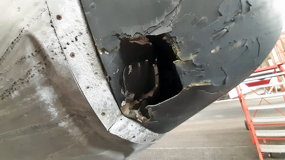
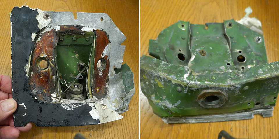
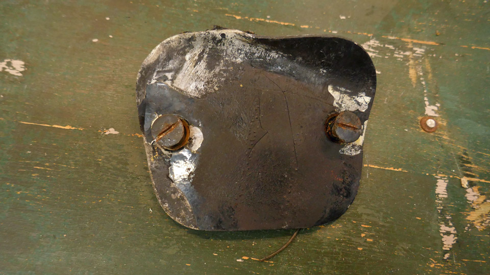
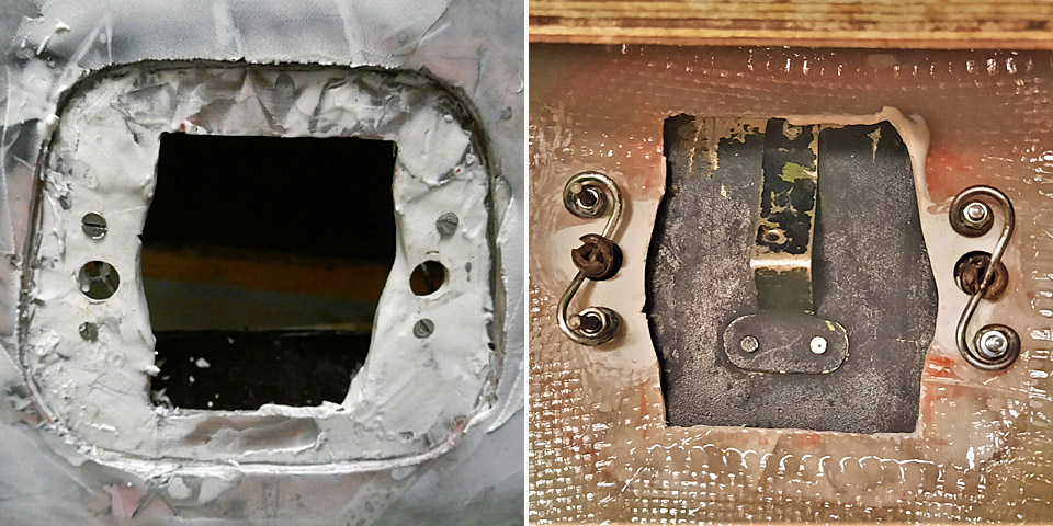
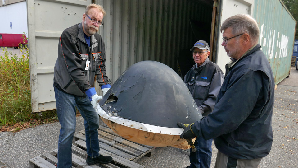
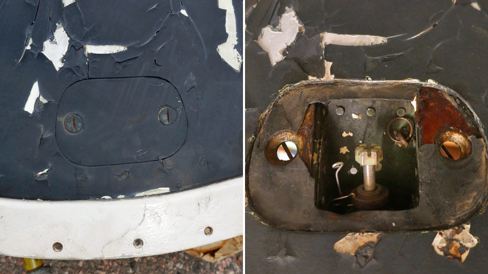
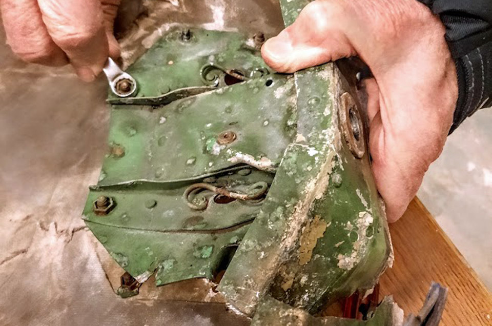
Photos by Reijo Siirtola The collision damage, which made a hole in the radome, has been repaired. There was a hole of about 30 x 20 cm on the edge of the radome and this was covered with laminated fibreglass. The collision has occurred right at one of the radome’s three fastening bolts and the hatch above it. In the collision the bolt and its cover frame have been damaged beyond repair, but we managed to straighten the badly bent bolt hatch and it can be reused. The radome is fastened on the outer rim of the nose bulkhead with three bolts.
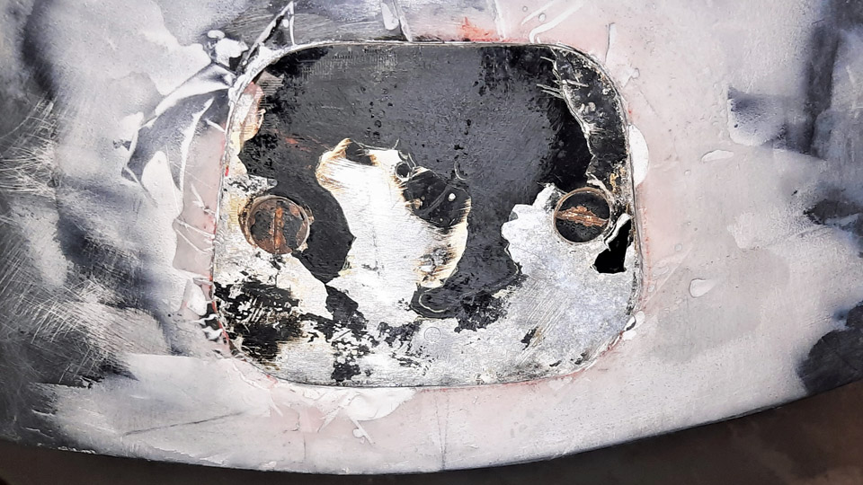
When the hole on the radome had been laminated and the radome’s crackled surface had been repaired, a base layer of black spray paint was applied. The surface was spackled and sanded to smooth the uneven areas. A final layer of paint will be added when the reparation of the damaged area has been completed.
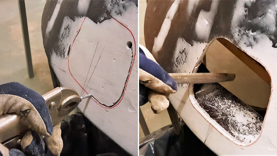
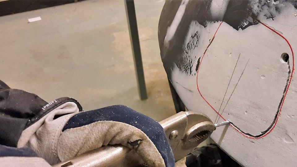
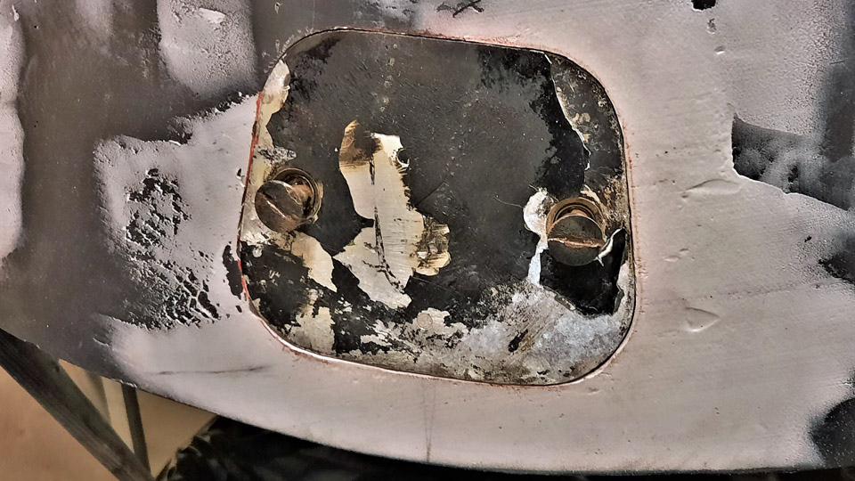
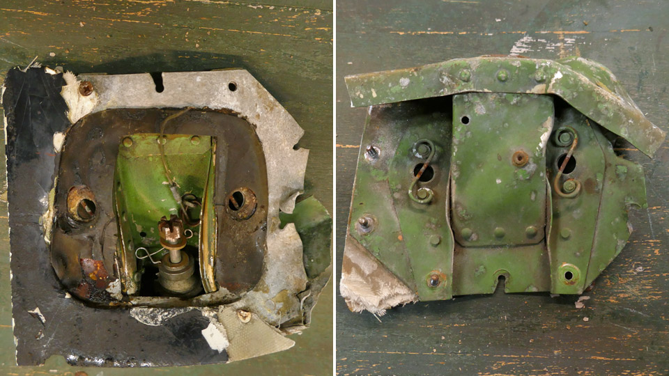
Photos by Reijo Siirtola Now it was time to make an opening on the radome for the fastening bolt’s hatch. The shape of the opening was drawn on the radome surface, using the original hatch as stencil. Then the opening was sawn along the drawn line, using a compass saw. The edges of the sawing line were ground smooth with a file. The opening edge needs also a collar against which the hatch is pressed, and which will have holes for the two quick-lock screws on the hatch. The locking springs of the two locking screws will be fastened inside the collar under the screw holes.
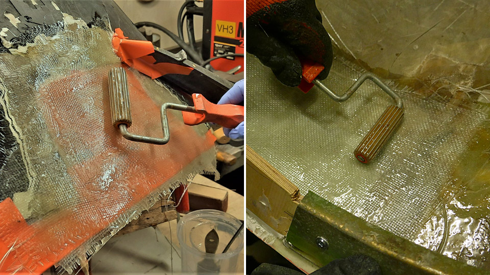
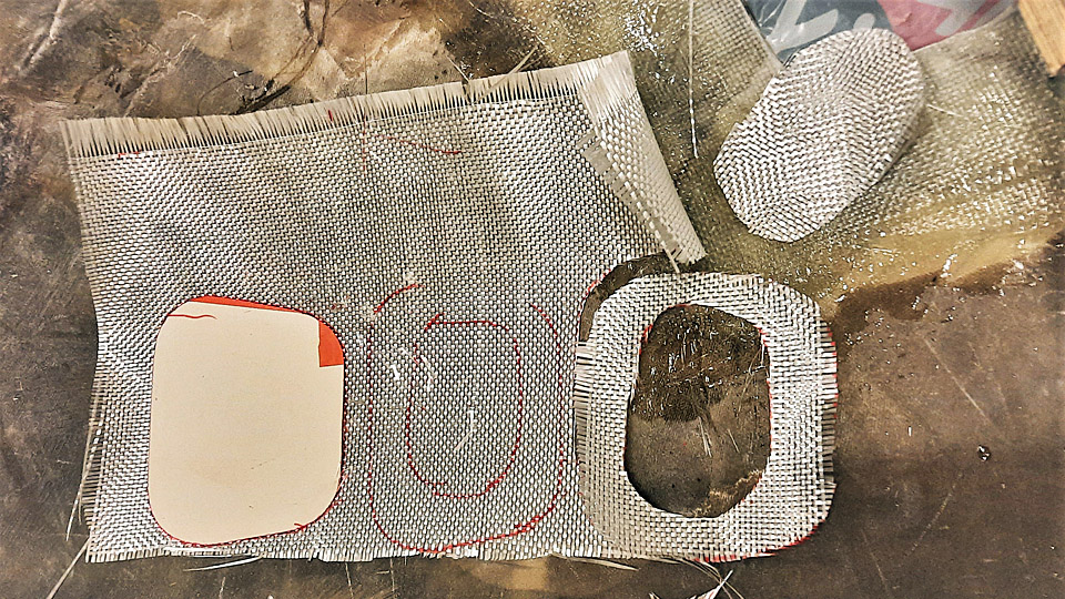
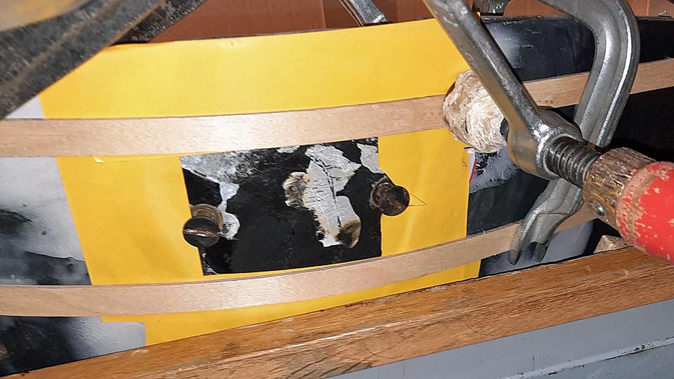
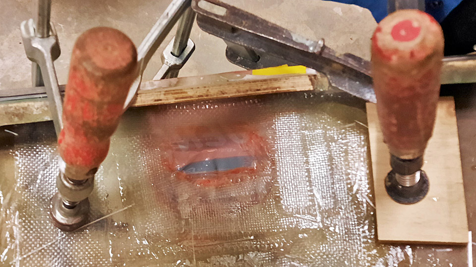
Photos by Reijo Siirtola The collar for the opening was made by laminating. Pieces of fibreglass mat were cut for the collar, with a hole in the middle. Then the bolt hatch was taped onto the edges of the opening and supported on it with two strips of plywood. The inner surface of the hatch was protected with plastic foil so that the hatch doesn’t get glued on the layers of fibreglass which are laminated under it. This way the hatch worked as a supporting wall for the laminating work. The fibreglass pieces were soaked in epoxy, and they were laminated with a roller, layer by layer, to cover the hatch opening.
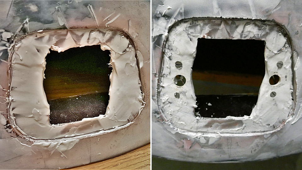
Photo by Reijo Siirtola When the laminated area had dried, the hatch was unfastened and the opening with its collar could be seen. The edges of the collar opening were smoothed. Then the holes were drilled on the collar for the two fastener screws of the hatch. The original locking springs of the screws were fastened on the lower edge of the collar, under the holes.
Left photo by Reijo Siirtola The functioning of the hatch was tested by pressing the hatch against the collar so that the lock screws were pushed into their holes. Then the hatch was locked by pressing the screws inwards and simultaneously turning them 90 degrees. The nick at the end of the screw locked on the spring under the collar. This functioned well so we had managed to assemble the hatch of the fastening bolt on the repaired radome.
Photos by Reijo Siirtola The following task will be to build a new bolt fastening into the damaged area so that the edge of the radome can be fastened on the rim of the Caravelle’s nose bulkhead below. The original bolt fastening was destroyed in the collision which hit the radome. Photos by Lassi Karivalo except if otherwise separately mentioned. Translation by Erja Reinikainen.
|
|
Avainsanat: aviation history, restoration, Caravelle, SE-DAF |
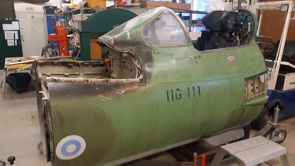
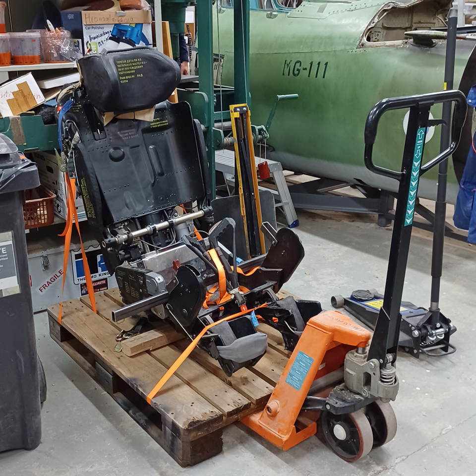
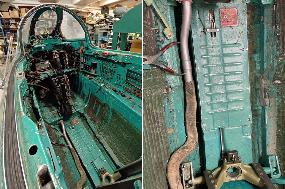
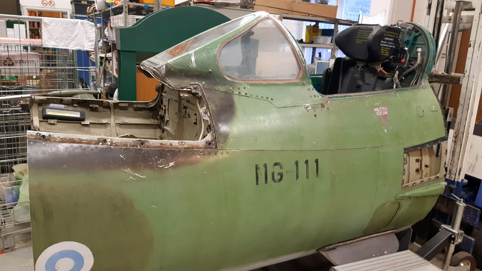
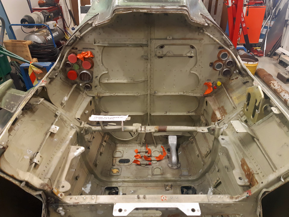
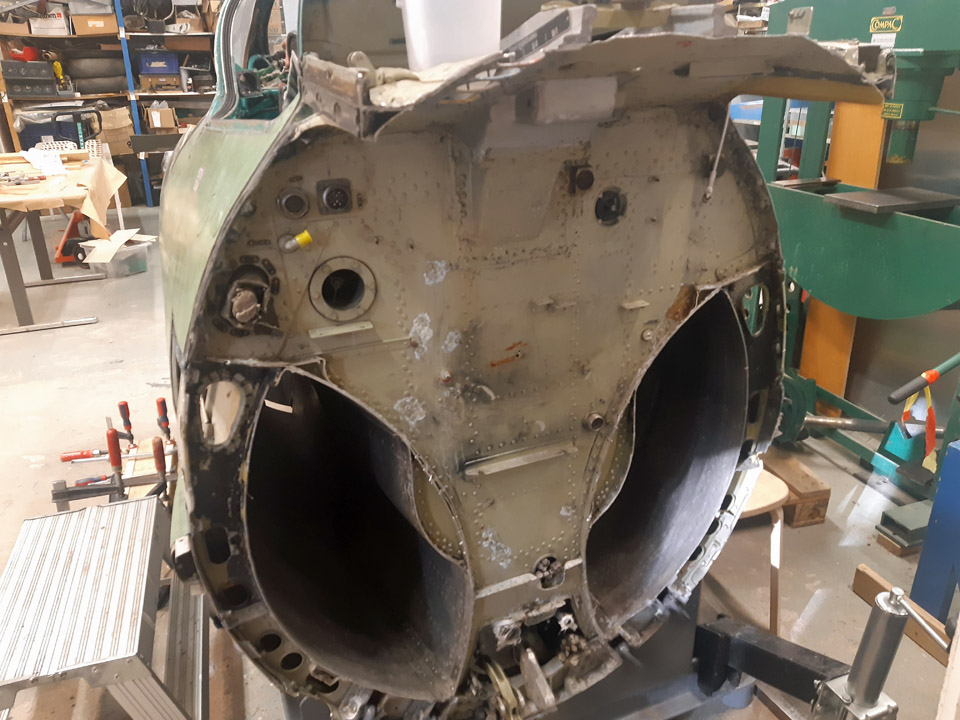
Detaching the MiG-21BIS fighter's pilot seatTorstai 2.2.2023 - Tuesday Club member In conjunction with the scrapping of the Mig 21 BIS fighter, the cockpit section was received by the Aviation Museum Society – and now it has been prepared at the Tuesday club to become an MiG 21 BIS cockpit simulator. The external equipment of the cockpit have already been detached, but the dismantling of the cockpit interior gadgets and wiring to make way for the simulator mechanisms, is still under work.
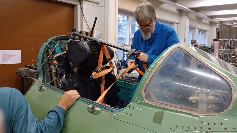
Photo by Pentti Kuusisto The dismantling of the cockpit section interior equipment has been hindered by the pilot’s KM-1 ejection seat, which is still in place. To dislocate the seat we received from the Karelian Wing Guild a special tool and a bar, with which the seat locking could be freed and subsequently lift the seat out of the cockpit. A retired Mig 21 BIS ejection seat mechanic from the Karelian Wing Guild paid us a visit and gave us instructions how to detach the seat.
After the start of the Tuesday Club’s spring season we turned our attention to the seat. Armed with the instructions and tools we had received from the Karelian Wing Guild together with the MiG 21 BIS manual, which we fetched from the archives of the Finnish Aviation Museum, we started to detach the seat.
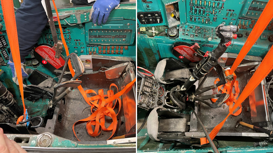
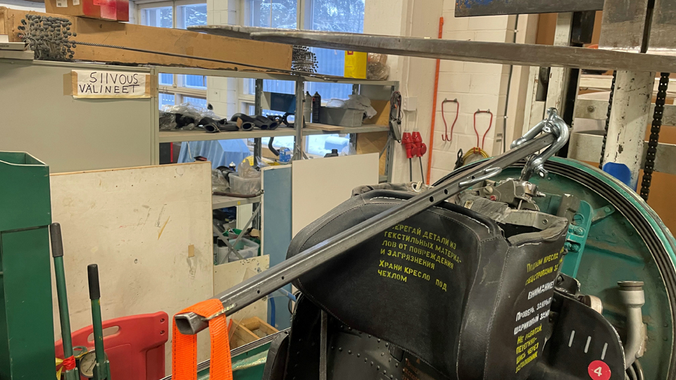
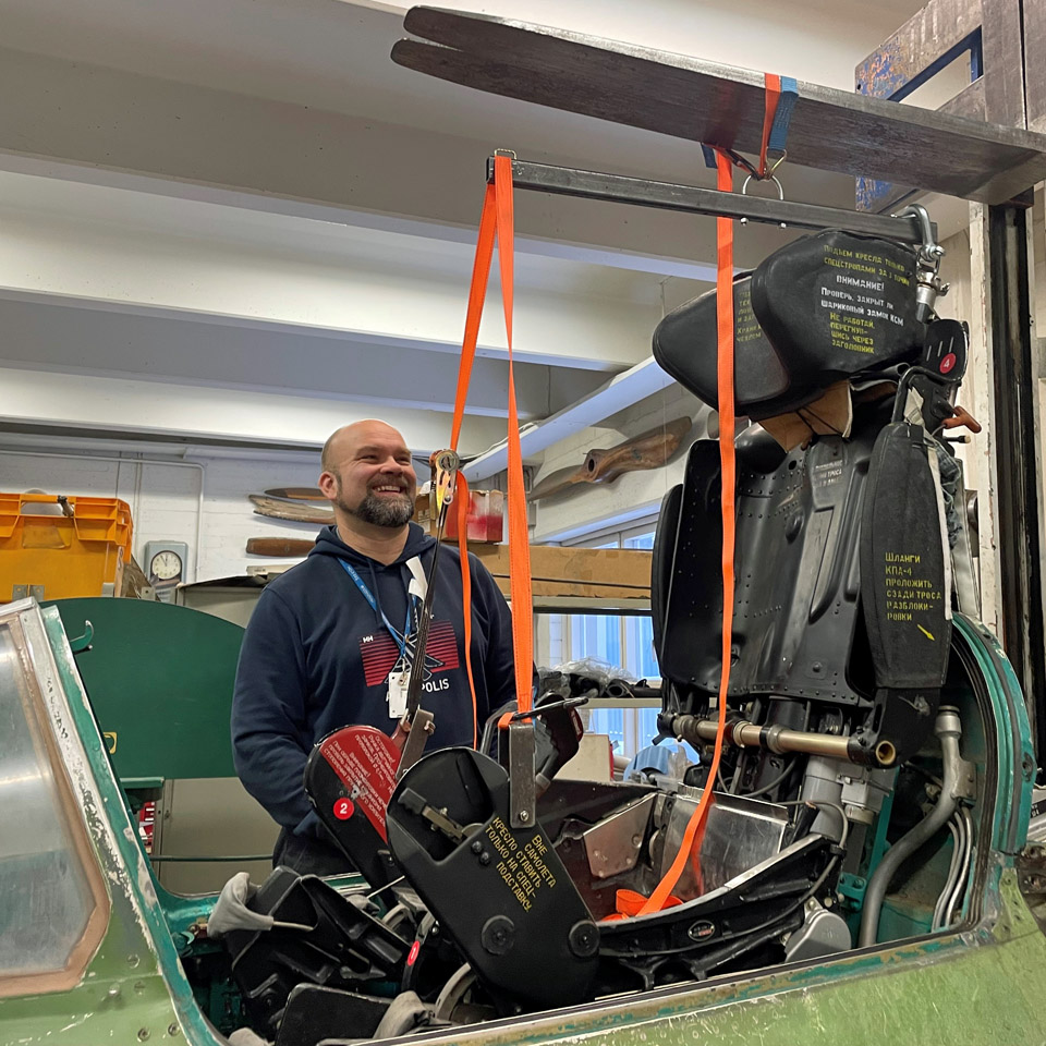
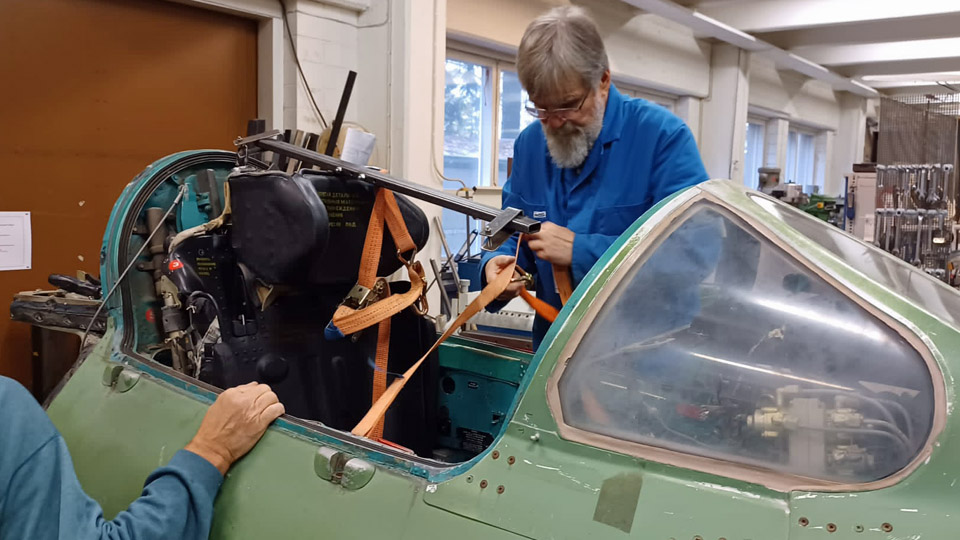
With the aid of the unlocking tool we managed to disconnect the locking under the seat. To lift the seat from its place, the metal bar used to unlock the seat was attached to it with cargo straps. Then the Museum forklift was driven by the cockpit, so that the forks raised to the upper position reached over the cockpit and the bar attached to the seat.
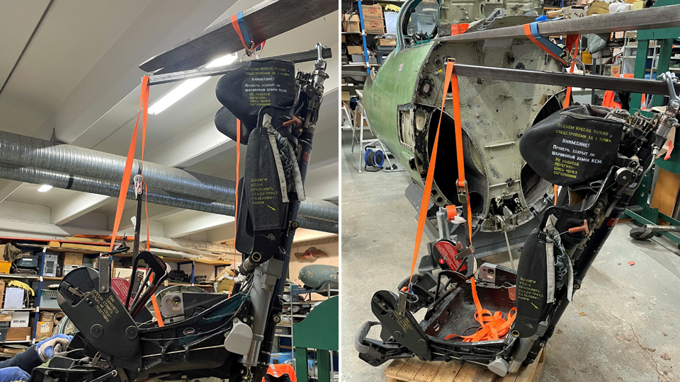
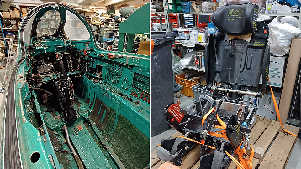
Photo by Juha Veijalainen. The bar was tied to the forks with straps, after which the seat could be hoisted out of the cockpit, hanging from the forks. It was a close shave whether the forks could be lifted high enough, because the restoration workshop ceiling beam was just above the cockpit and there was only centimetres of extra space. However, we managed to swing the seat over the cockpit side with a bit of manual help, and lowering the forks settled the seat onto a wooden pallet on the restoration workshop floor. Thus the MiG- cockpit was freed of the seat and we gained plenty of space to carry on with dismantling the wiring and gadgets to make way for the simulator equipment.
Photos by Juha Veijalainen. Because there was no further restoration or maintenance work planned for the seat at this stage, it was attached with straps to the pallet and taken to storage into the container at the Museum yard used for DC-3 (DO-5) parts. Translation by Matti Liuskallio. Photos by Antti Laukkanen except if otherwise mentioned. |
|
Avainsanat: aviation history, restoration, Tuesday Club, MiG-21BIS, MG-111 |
The spring season 2023 for the Tuesday Club got startedLauantai 21.1.2023 - Tuesday Club member After a well-earned Christmas break work continued on January 10th, 2023 from where it was left on going for the break.
Photos by Reijo Siirtola The repair of the Caravelle III (DAF) nose radome damage was started by making an opening for the cover for the attachment bolt in the damage point, which was laminated over. An opening was sawn according to the measurements of the cover with a keyhole saw, after which a rabbet was laminated along the edges of the opening, against which the cover will be pressed and locked to the frame of the attachment bolt. Simultaneously the straightening of the damage to the nose pressure bulkhead outer circle was started. The crushed bulkhead circle has to be straightened in order to get the radome edge to be pressed tightly against the bulkhead circle and locked in place with three bolts.
Photo by Heikki Kaakinen By the beginning of the summer the starboard wingtip and the starboard horizontal stabilizer damages have to be repaired, so that everything will be ready when the Caravelle III (OH-LEA , ex SE-DAF) ) called “Bluebird” in Finnair colours will be transferred from the Pansio hall in Turku to close proximity of the Turku Airport terminal.
Photos by Juha Veijalainen The surface handling of the parts of the Caravelle towbar, which was brought along with the Caravelle III from Arlanda, is underway. The towbar used by SAS will be restored to the livery of the towbars used by Finnair. The sandblasted parts of the towbar are being painted with the grey Isotrol primer. The surface colour will be “Finnair blue”, apart from the towbar ends, which will be painted with yellow high visibility paint.
Photo by Antti Laukkanen
Photos by Juha Veijalainen
Photo by Osmo Väisänen We finally managed to dislocate the pilot’s seat from the cockpit of the MiG 21 BIS (MG-111), which will be transformed to a cockpit simulator. The dislocation was made possible by a dislocation bar, instructions and a manual received from the Guild of the Karelian Wing. Lots of original wiring still needs to be removed from the cockpit, before we can have access there to install the actual simulator equipment. The covering of the engine air intake duct openings in the cockpit rear and front bulkheads with plexiglass is underway.
Photo by Heikki Kaakinen Work continues with the Caudron C.50 (CA-50) aircraft. The re-covering of the fully restored port elevator with linen fabric was started and the unsatisfactorily tightened patches on lower wings were continued to be replaced with modern Oratex-material. The winter season barely allows any work on the interior of the DC-3 (DO-5) fuselage owned by Aviation Museum Society Finland. Work will continue with the warmer spring weather. Well, we have achieved something; the door between the cockpit and the cargo hold has received a new coat of paint. Translation by Matti Liuskallio. |
|
Avainsanat: aviation history, restoration, MY-14, VL Myrsky, Caudron C.59, CA-50, MiG-21BIS;MG-111 |
Caravelle's restoration work is continued in PansioPerjantai 20.1.2023 - Reino Myllymäki The restoration work of the Sud Aviation SE 210 Caravelle III SE-DAF continues in Pansio after the short Christmas break.
Photo by Ismo Matinlauri. A workshop has been established in the cold port hall’s heated staff rooms. Even the old shower room has now got a new purpose as a workspace.
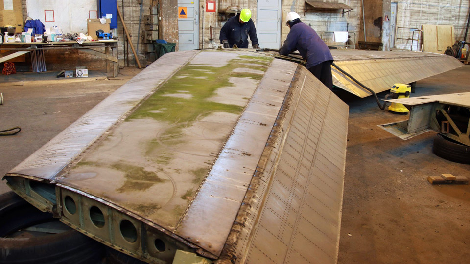
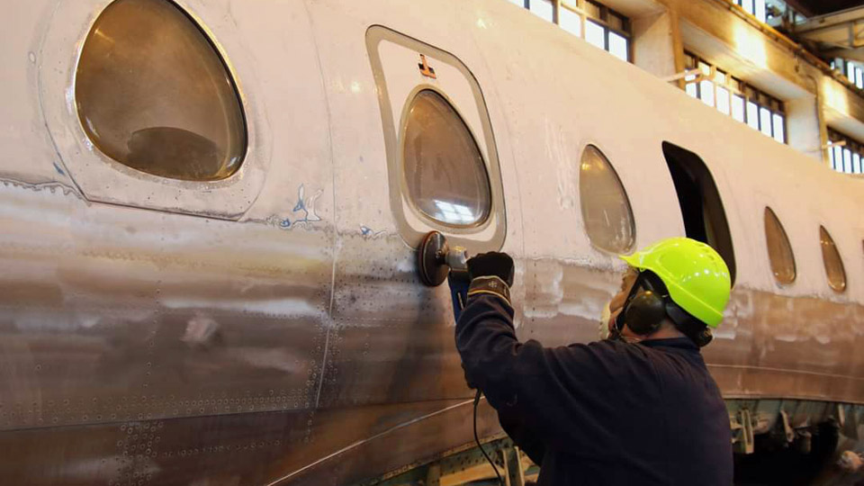
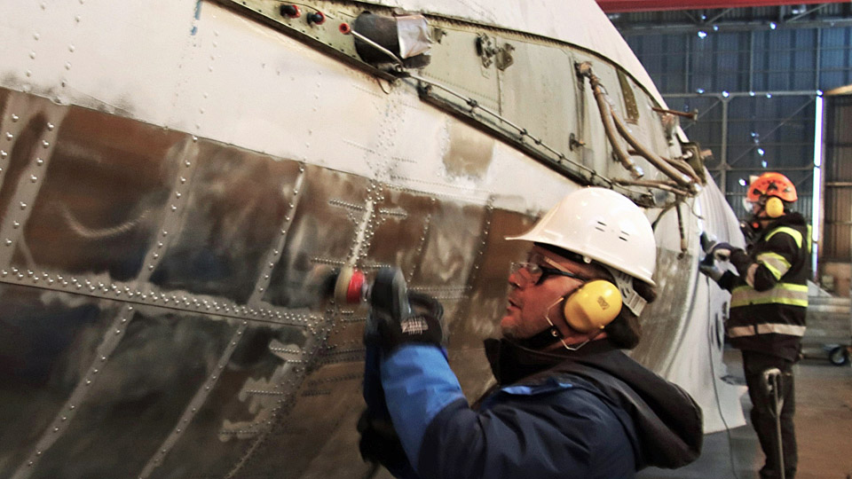
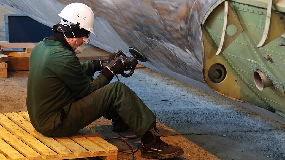
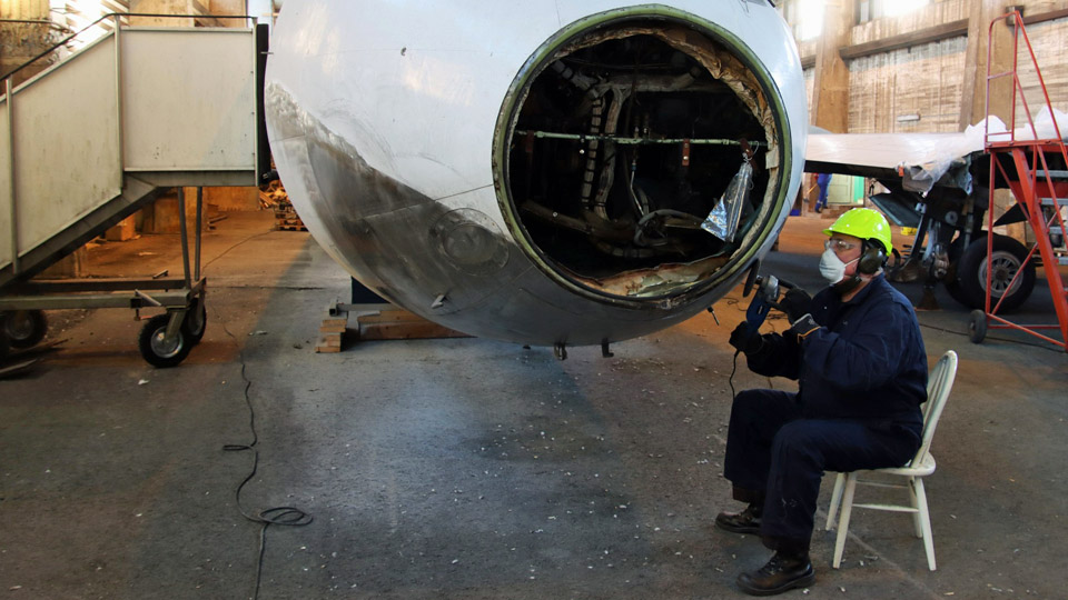
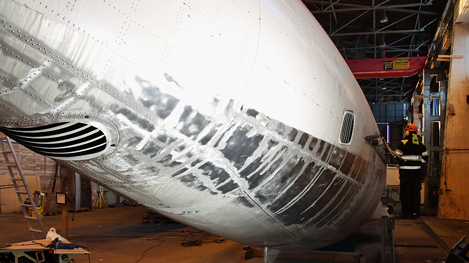
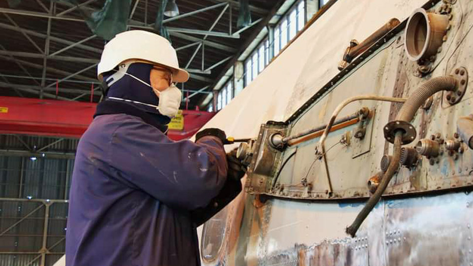
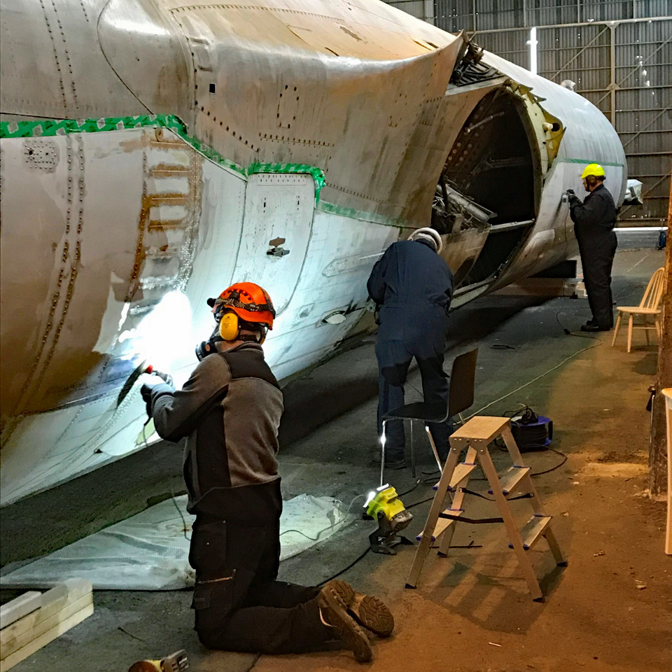
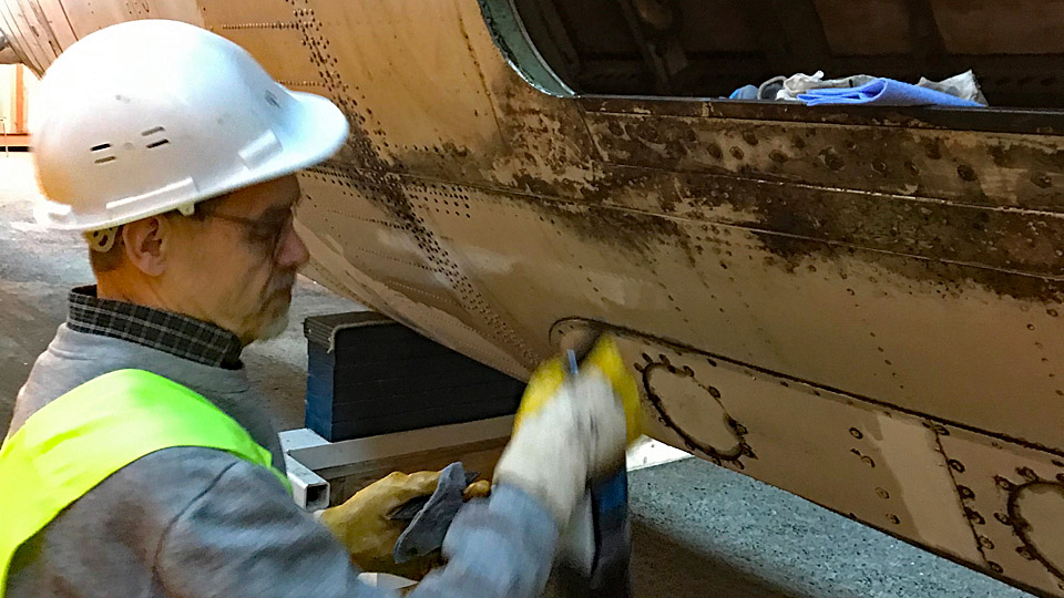
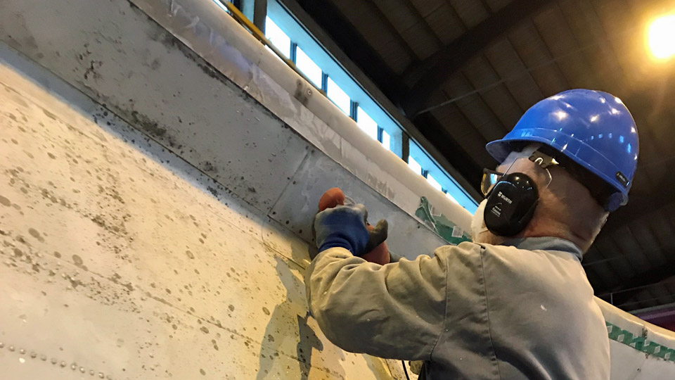
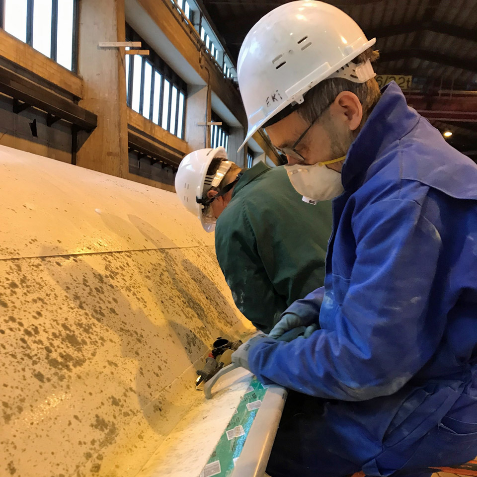
In the unheated large hall area some work can be done during the winter. Grinding and polishing of the aircraft fuselage is possible, but it can’t be painted during the cold season. Some grinding is necessary to remove a section of the white paint which in the former SAS paint scheme reaches down the sides of the fuselage. In the spring the aircraft will be painted to the Aero Oy paint scheme. The section which needs to be removed by grinding gets wider towards the tail of the aircraft.
Some dismantling and assembling will be done during the winter. The Pansio restoration teams aims to work every week on Mondays, Wednesdays and Fridays. Photos: Jouko Tarponen if not mentioned otherwise. |
|
Avainsanat: aviation history, restoration, Caravelle, SE-DAF |
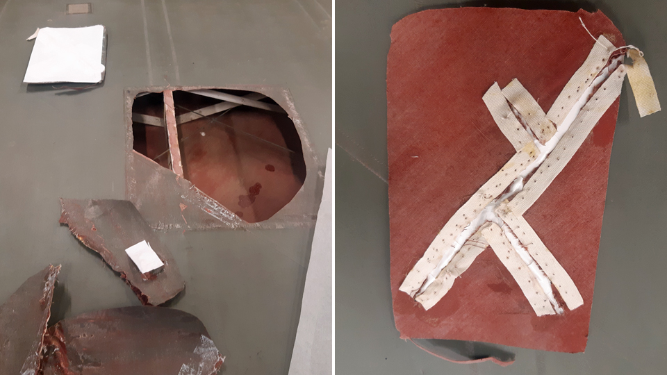
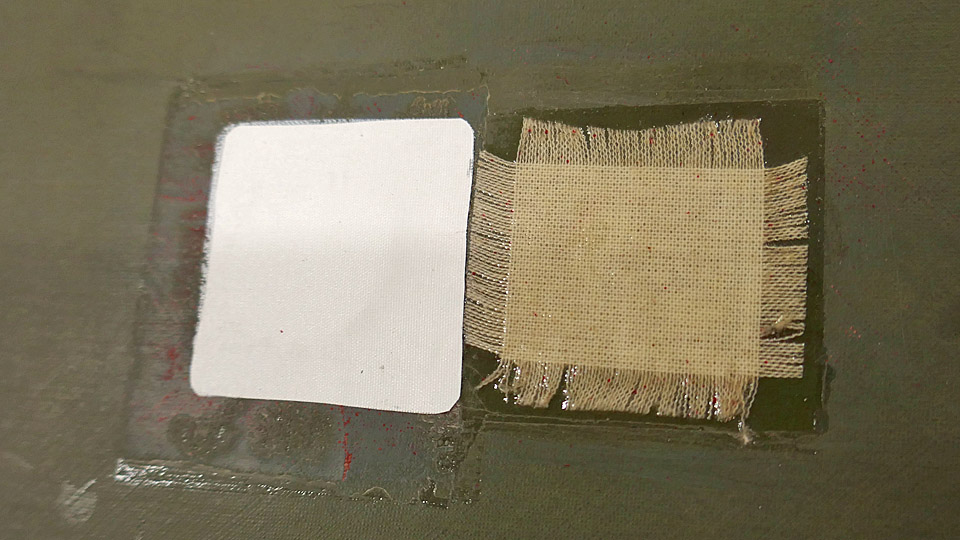
Changing the patches on lower wings of the Caudron to a modern patching materialMaanantai 26.12.2022 - Tuesday Club member The patching of the holes on the lower wings of the Caudron C.59 CA-50), the advanced trainer from the 1920’s, was finished in 2021. More than a hundred holes of various sizes could be found on both wings. To patch the holes on the lower wings we had used first cotton and then linen fabric. We had sewn together the tattered edges of big holes before gluing the patches on them. The patches had been fringed on their edges in the manner of the 1920’s, and they were glued on the holes using nitrocellulose lacquer, i.e. the tightening lacquer for the covering fabric.
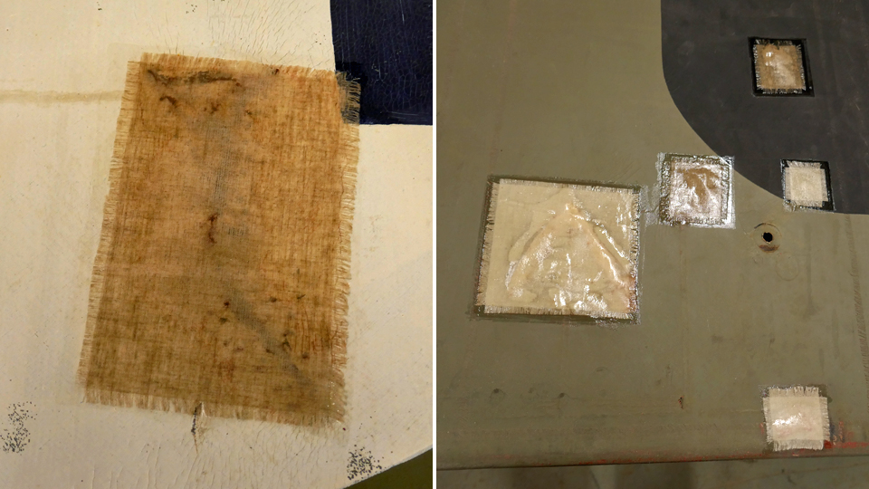
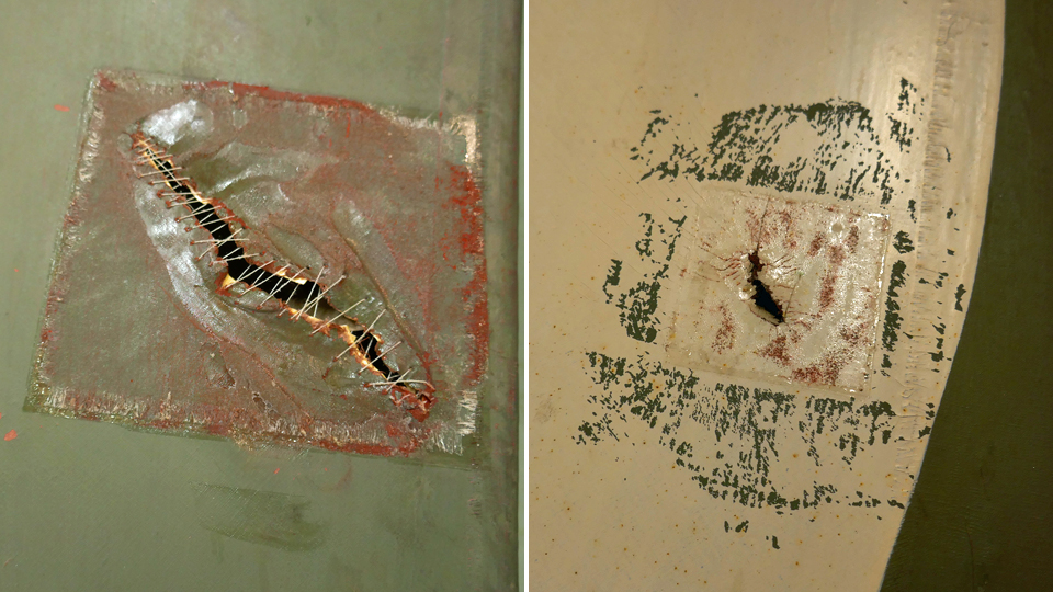
In the autumn of 2022 we started the changing of the fabric patches on the lower wings with the Finnish Aviation Museum’s staff supervising the work. The reason for this was that the larger patches of fabric, and especially the linen patches, hadn’t properly tightened. There were also problems with those patches, where the edges of the holes had been sewn together. In these places the stitches had remained lumpy under the patches in a disturbing manner, probably because the fabric hadn’t tightened enough on the stitches. Patches on the wings have to be smooth at least for aerodynamic reasons.
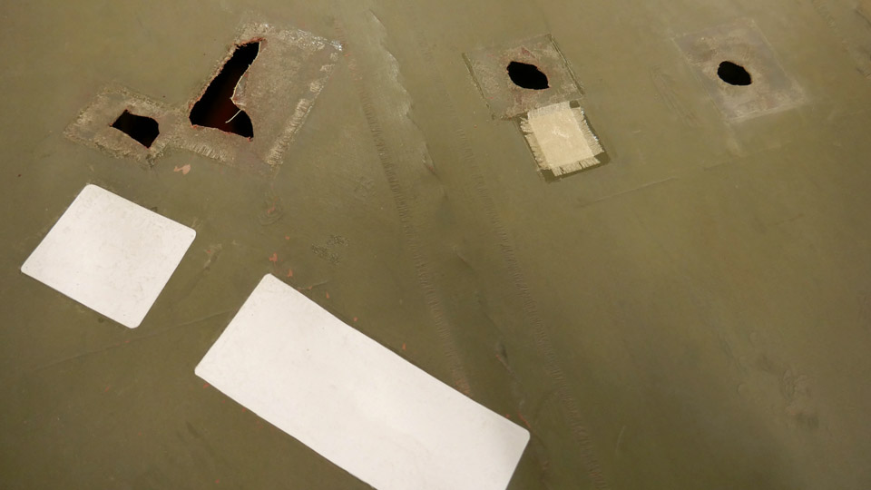
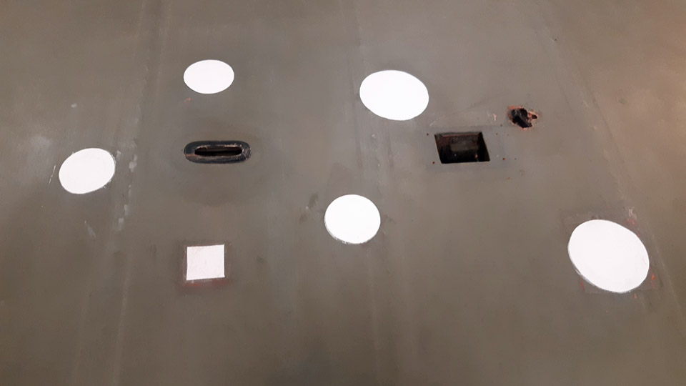
The Museum decided to have the inadequately tightened linen patches and the fabric patches containing stitches to be changed to a new material. As the new material the modern heat-tightening Oratex- material, resembling the 1920s style, was chosen. Patches made of thin Oratex-material, painted in the patinated greyish green hue, produced inconspicuous and at the same time aerodynamically extremely smooth patches, compared with the fabric ones made with tightening lacquer.
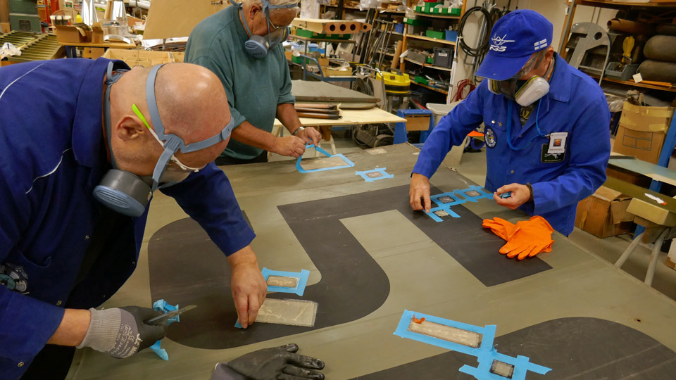
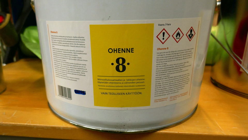
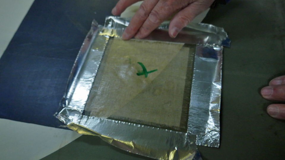
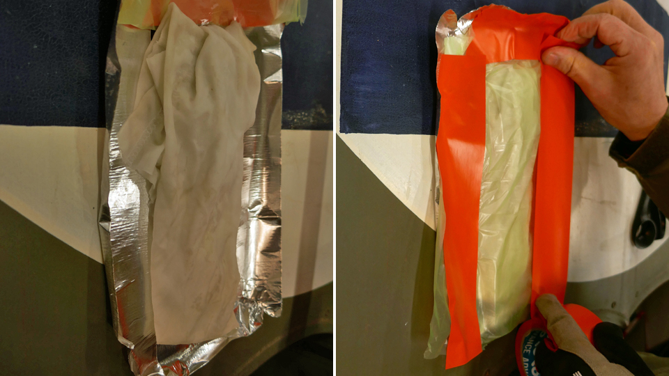
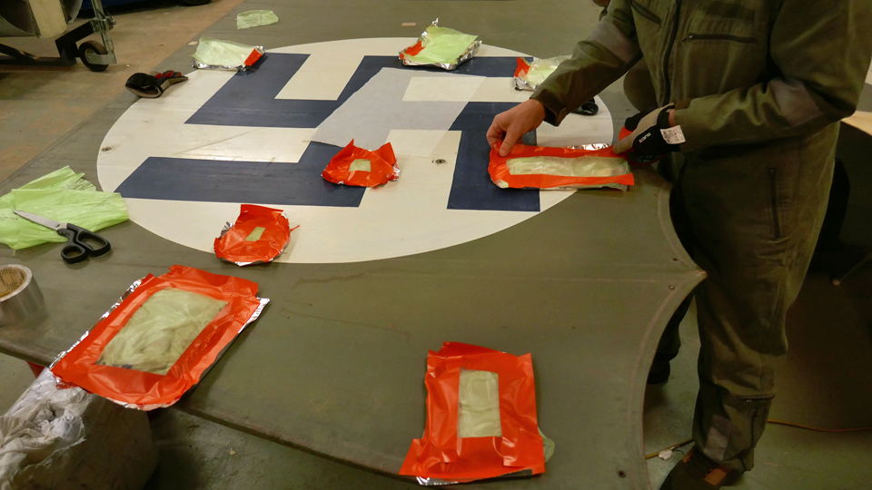
To replace the patching material the fabric patches were loosened using thinner for nitro cellulose lacquer (Thinner 8). The patch was surrounded with aluminium tape, so that the thinner wouldn’t damage the 1920s covering fabric. After this a thoroughly Thinner 8 soaked fabric, which was covered with a sheet of plastic foil, was placed on the patch. The foil was taped tightly on the edges to keep the fabric wet and to prevent the thinner from evaporating. After a few hours “the package” was opened and the cotton or linen patch, glued with nitro cellulose lacquer, could be neatly detached. After this the edges of the holes without a patch were cut clean. Patches, with tattered edges sewn together, were cut completely open. Holes with tattered edges will not be sewn anew.
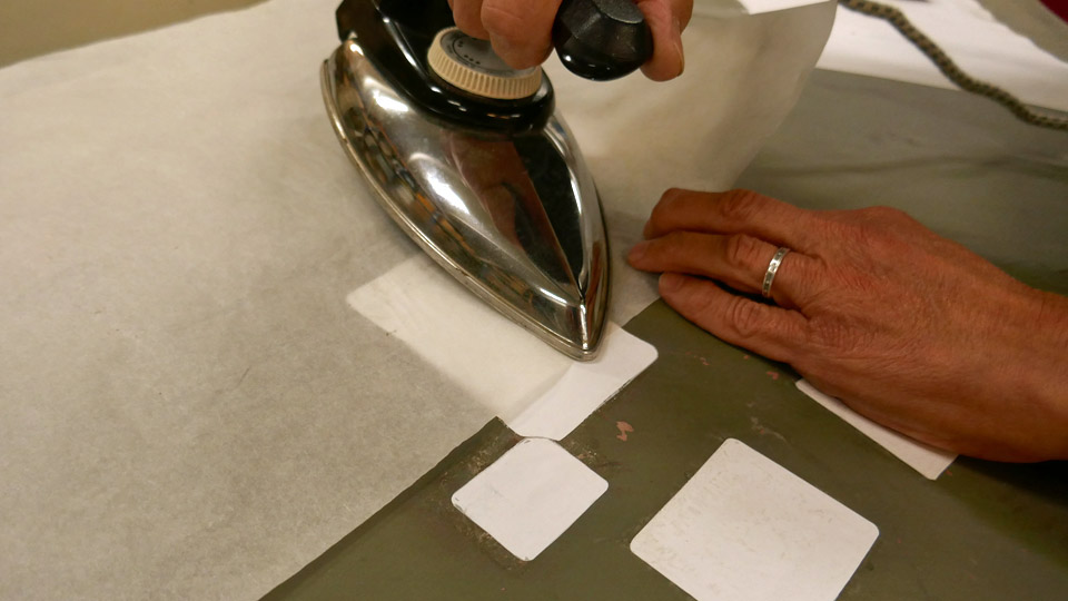
Now the patching of the cleaned holes could be started with Oratex-material. For each hole a larger round or rectangular piece was now cut out of the Oratex-material. After that the patch was glued and tightened on the hole by heating the patch with an iron, which was pre-heated to a suitable temperature, using a protective paper. The heating melts the glue from the underside of the patching material, fastening the patch to its place and tightening the fabric smooth.
This modern material is really handy to use and the patches turned out to be very smooth and tidy. There’s also the extra bonus of not having to protect oneself against the toxic fumes of the nitrocellulose lacquer. The appearance of Ortex- patches differs, however, from the traditional fabric patches with fringed edges from the 1920s. The work will continue in the spring season of 2023. Photos by Lassi Karivalo. Translation by Matti Liuskallio. |
|
Avainsanat: aviation history, restoration, Tuesday Club, Caudron C.59;CA-50 |
Washing the MiG-21BIS cockpit entity rear bulkhead and covering of the air ductsTorstai 22.12.2022 - Tuesday Club member Suomeksi Preparations to transform the cockpit entity of the MiG-21BIS (MG-111), owned by Aviation Museum Society Finland, into an experience simulator have been going on at the Tuesday Club during the whole autumn season. Clearing the cockpit interior of instruments and wires to make way for the simulator equipment is still going on. Along with that we have concentrated on the work with the external surfaces of the cockpit entity. Later the term simulator will be used instead of cockpit entity in this blog.
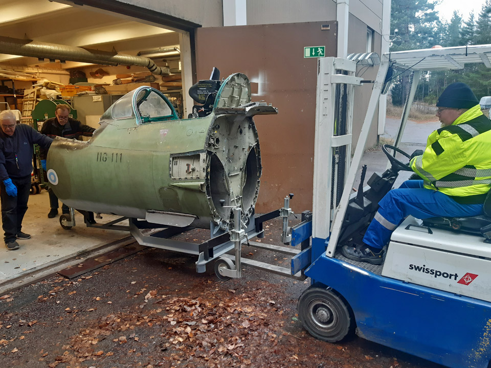
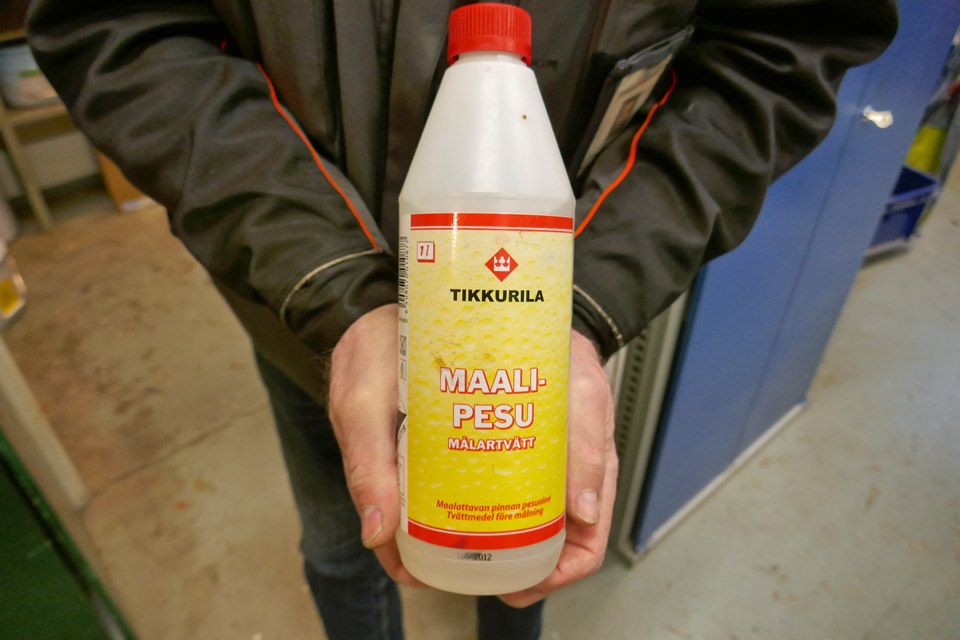
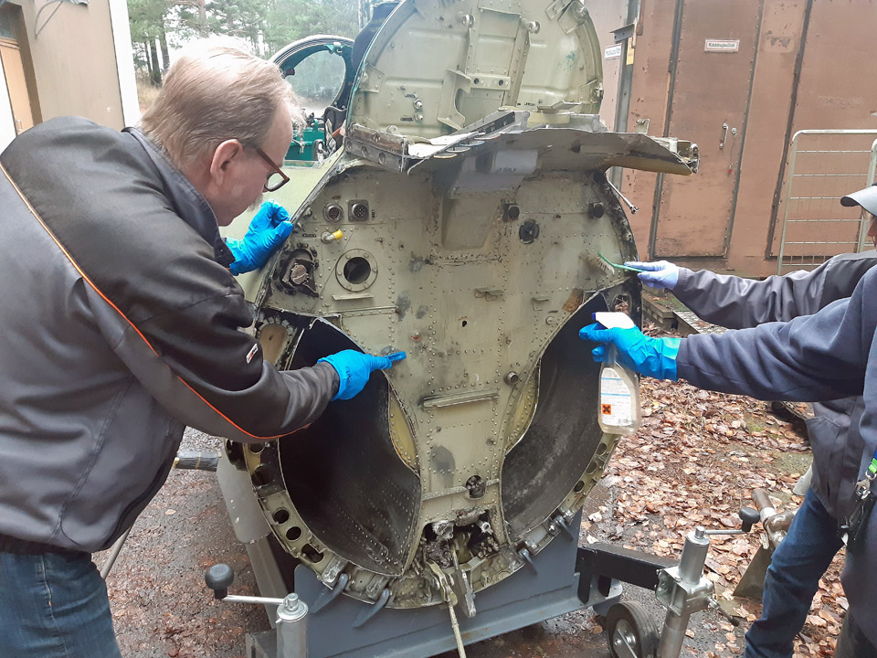
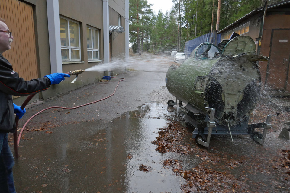
The simulator rear bulkhead has been cleared of all the wires and gadgets. After that the bulkhead was cleaned with Tikkurila Oy paint cleansing liquid, prior to the actual painting of the bulkhead. For the cleansing the simulator was pushed out of the Finnish Aviation Museum’s restoration workshop into the yard. Paint cleansing liquid was sprayed with spraying bottles onto the bulkhead and the surface was brushed clean. After that the cleansed surfaces were rinsed thoroughly with water using the museum restoration workshop’s fire hose.
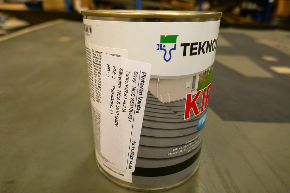
The MiG-21BIS simulator rear bulkhead will be painted to the shade of the faded green exterior surface. This way it will visually match the simulator’s original faded green colour. The front bulkhead will be painted with the same colour. To obtain the colour we went to the Vantaa branch of Pintaväri, carrying one fairing with a faded surface. The shade of green was defined from the fairing (NCS S5010G5OY) and accordingly Teknos Ltd KIRJO paint was mixed for painting the rear and front bulkheads.
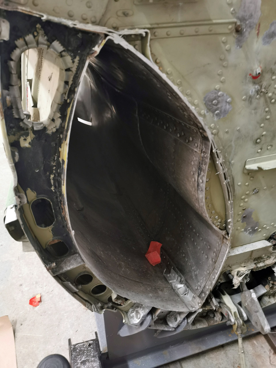
However, we decided to postpone the painting of the cleansed rear bulkhead until the air duct openings in the rear bulkhead had been covered. Closing the rear and front bulkhead air ducts is primarily a safety issue. The ducts are large enough for a museum visiting small child and also a bigger one to crawl inside the duct. In the simulator’s front bulkhead there’s also the opening of the nose wheel well.
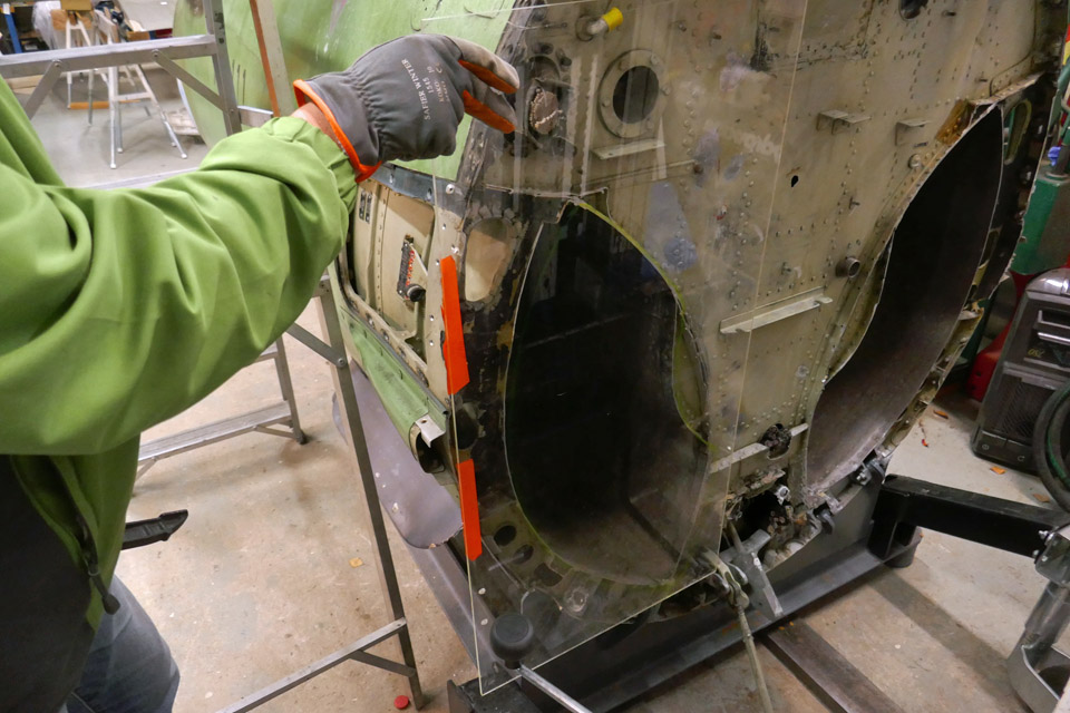
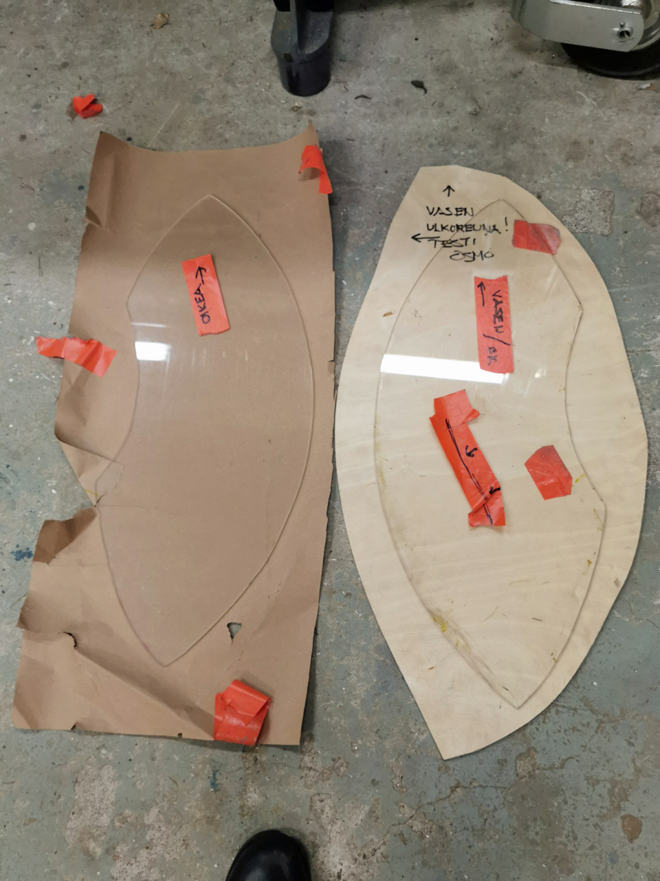
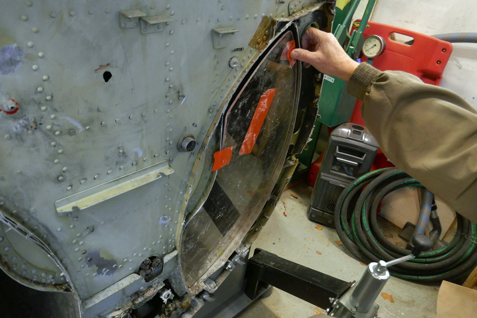
We decided to cover the air ducts with sturdy transparent plexi glass plates. This way one can see inside the duct. The assembly of the plexi glass covers will be done so that the pieces aren’t easily detachable, so that the museum visitors wouldn’t be tempted to take them off, but in such a way that they could be easily removed if necessary. We started to make the plexi glass covers with the left air duct opening in the rear bulkhead. With this opening it can be tested how to cut, shape, and implant the plexiglass cover into the duct opening. Only after this plexiglass cover has been fitted into the air duct opening, will we start making the right air duct plexiglass lid.
In the Finnish Aviation Museum’s material container we found suitable 5 mm thick polycarbonate plexiglass. It can be easily sawed and shaped and is not prone to crack when worked on.
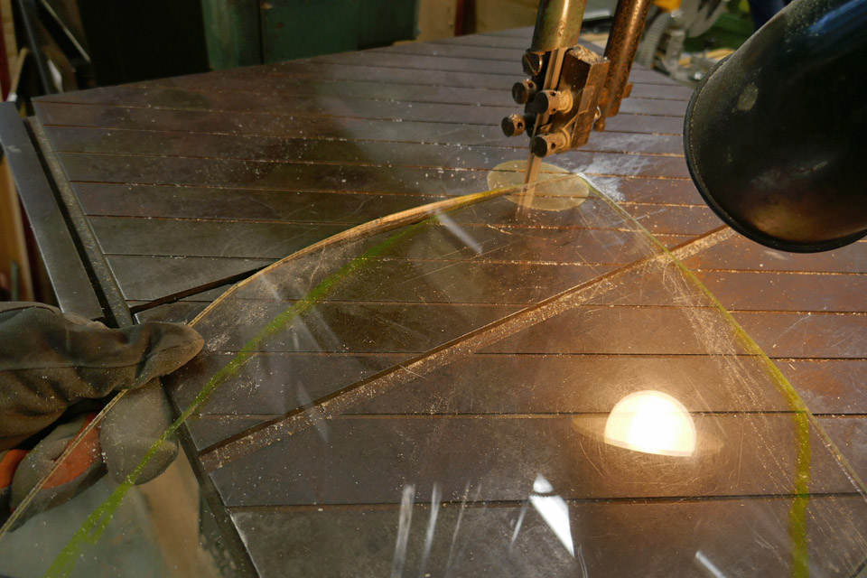
A piece of plexiglass was placed on the opening of the air duct and the shape of the duct was drawn on it. After that the plexiglass was sawed with a band saw along the drawing line to its preliminary shape. By fitting the piece of plexiglass on the opening it was moulded phase by phase to the shape of the air duct rim. The aim was to achieve a shape where the plexiglass sits suitably tightly inside the rim of the duct. Eventually the plexiglass was shaped so that it fitted into the duct opening.
We used the left lid as a template for the right air duct, albeit as a mirror image. We assumed that the ducts would be identical. After having cut the plexiglass for the right air duct and tried it on the opening, we found out that the ducts weren’t fully identical – oh well, “big country, big tolerances”. After some additional shaping the plexiglass it fitted snugly to the inside rim of the duct. Now both the lids of the simulator rear bulkhead were ready to be fastened.
To fasten the plexiglass lids we decided to use L-shape holders. One end of the holder would be fastened to the plexiglass cover, the other to the rim of the air duct. For making the holders, strips of aluminium were cut off to suitable pieces and bent into L-shape. Fastening the plexiglass covers will take place after the Tuesday Club’s Christmas break.
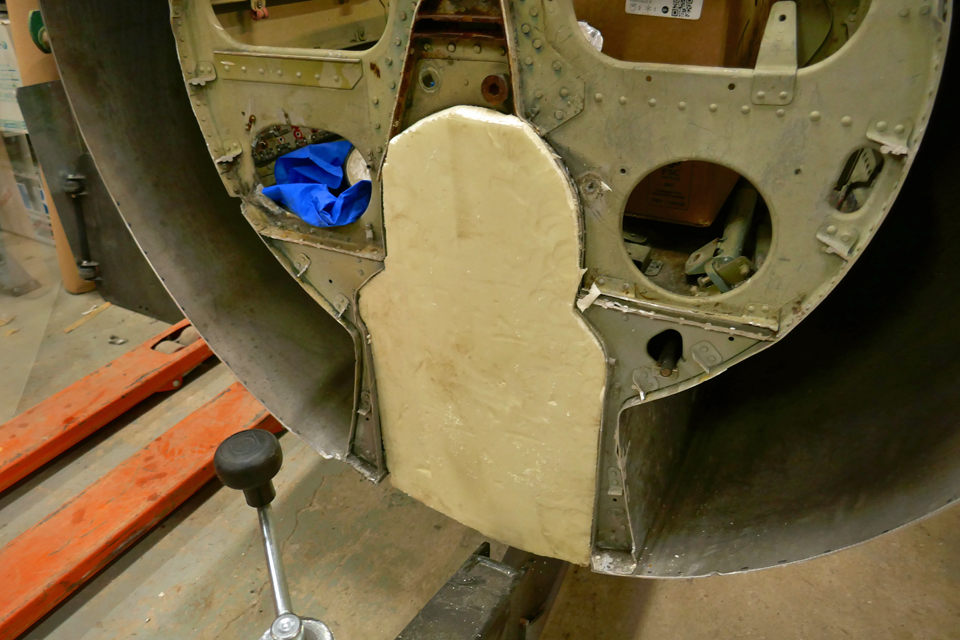
Along with the rear bulkhead plexiglass covers, work went on with covering the front bulkhead landing gear well. Unlike the engine air intake ducts, the cover to the landing gear opening will be made out of laminated wood. First we made a template the shape of the landing gear opening out of easily workable insulation board. According the insulation board template, the cover of the landing gear opening was sawed out of 15 mm thick laminated wood. The shaping of the cover to its final form and fastening it into place is postponed to the Tuesday Club’s spring season. |
|
Avainsanat: aviation history, restoration, Tuesday Club, MiG-21BIS, MG-111 |
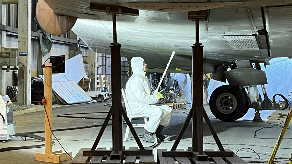
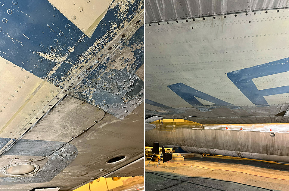
Caravelle - Dry-Ice in the AirTorstai 15.12.2022 - Ismo Matinlauri At the end of the restoration team’s autumn session we managed to clean the lower surfaces of the wings using dry-ice blasting method. This method was selected for cleaning the worst (i.e. dirtiest) areas fast, and in a safe and clean way. The achieved time saving was also considerable, shortening the overall project time. This means that when spring arrives, our volunteers can continue grinding and polishing the fuselage and wings, and we can also start installing the engine nacelles.
The dry-ice blasting was done professionally by Dry Ice Finland in a few days. The methodology in brief: Dry-ice (carbon dioxide) is pure carbon dioxide in solid form, the temperature is about -79 °C. In dry-ice blasting the dry-ice pellets are blown with high pressure to the surface to be cleaned. Once the pellets hit the surface, they evaporate (sublimate) into the air and the dirt removed will fall down for easy cleaning as needed. Dry-ice blasting is a totally dry, chemical-free and almost wasteless method.
The photos of the aircraft’s wing surface before and after cleaning show the results of dry-ice blasting.
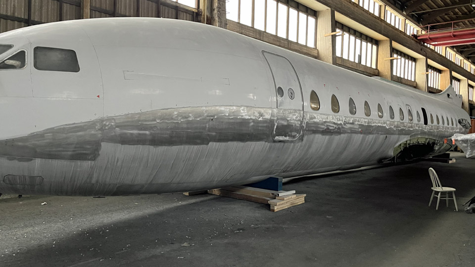
While the dry-ice cleaning was going on, the Pansio volunteers managed to grind from one side of the fuselage under the windows an 18 cm wide belt of white paint, which originates from the SAS paint scheme. The aim is to follow Finnair’s OH-LEA paint instructions, and we shall polish the lower part of the fuselage, up to the lower edge of the windows. The other side will have to wait until the weather warms up – it is a good starting point when our work continues next spring. Photos: Ismo Matinlauri. |
|
Avainsanat: aviation history, restoration, Caravelle, SE-DAF |
Caravelle's radome is repaired and repaintedKeskiviikko 7.12.2022 - Tuesday Club member The radome, disassembled from the nose of the Caravelle III (SE-DAF) which is now owned by Aviation Museum Society Finland, is being repaired at the Tuesday Club. Its painted surface has cracked, and it has been also badly damaged in a collision.
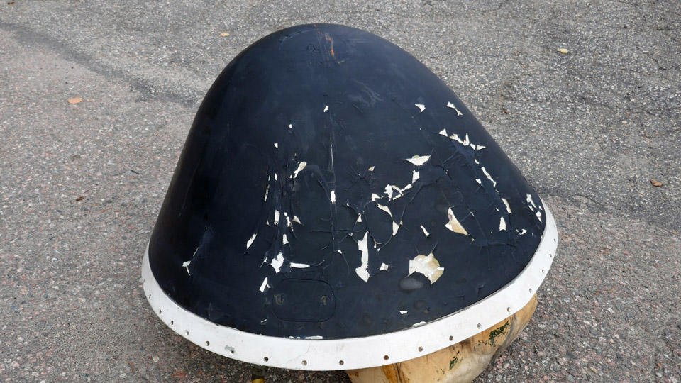
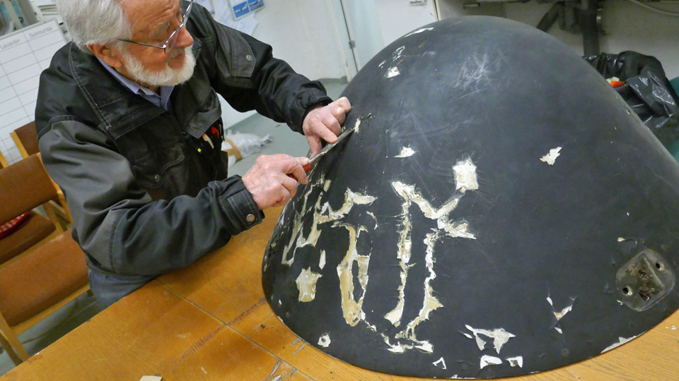
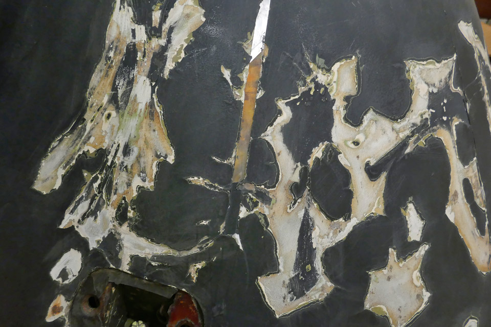
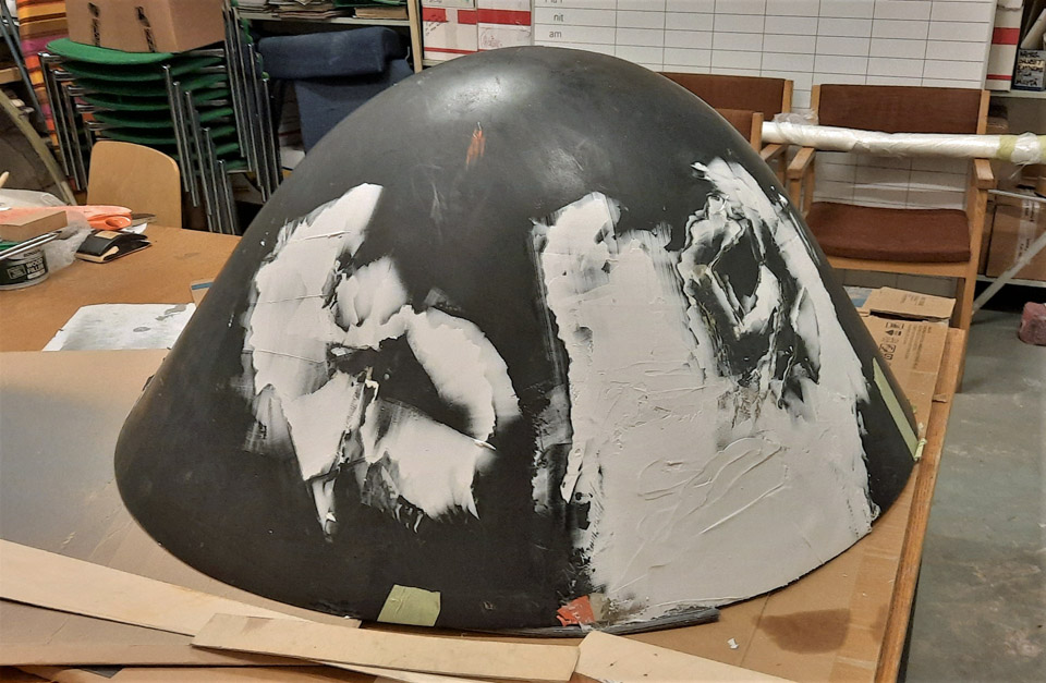
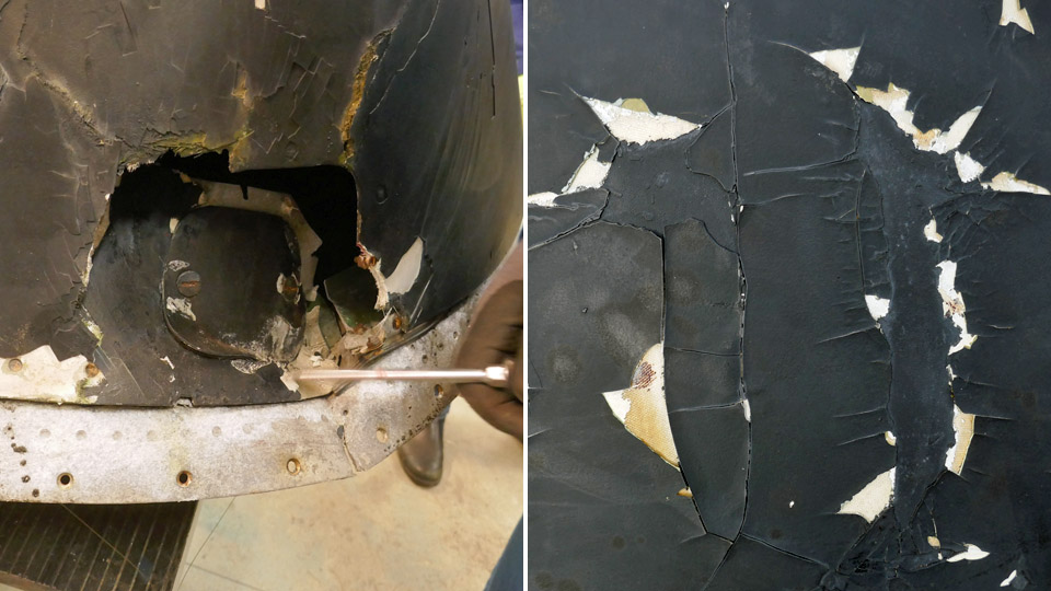
The radome is made of Kevlar and its surface has originally been puttied and painted with matt black paint. The black paint surface has cracked and peeled off in several places. The white putty and the Kevlar surface under it are visible in the damaged areas.
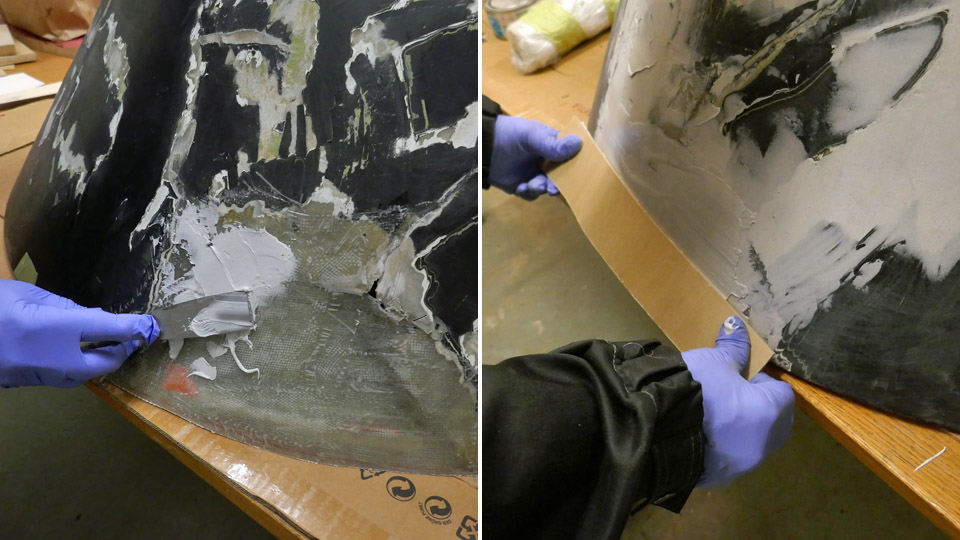
The cracked paint and the white putty on the radome surface were chiseled off down to the Kevlar surface. This caused grooves and holes on the radome’s surface. The Tuesday Club team decided to fill the grooves and holes with epoxy filler. This material was also a good choice for smoothing and levelling the radome’s damaged area which had been patched with glass fibre fabric.
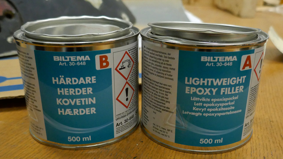
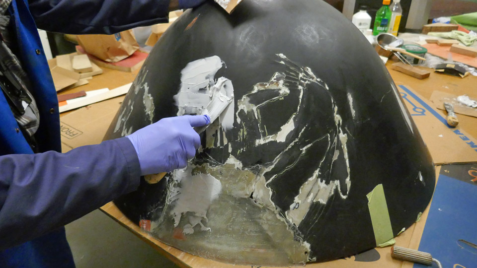
Light epoxy filler (Lightweight Epoxy Filler) and hardening agent were purchased from Biltema. Following the product instructions, a portion of filler was mixed. The filler was spread with metal spatulas on the holes on the radome’s surface and on the damaged area, which had been laminated with glass fibre fabric. A thin flexible plywood veneer was also used when spreading the filler, pulling it on the radome’s surface, following its curved shape. The filler followed well the curved shape of the radome. Several portions of filler had to be mixed before all the grooves had been filled and smoothed.
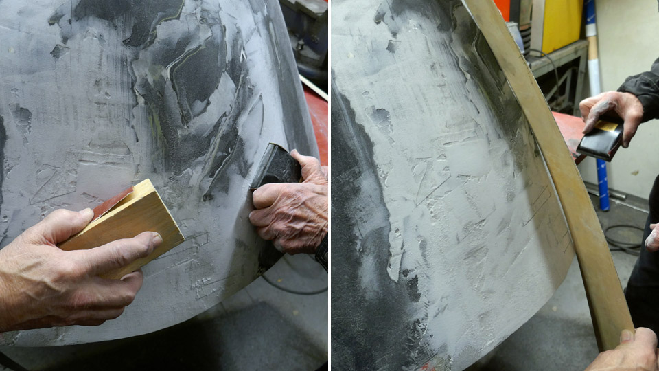
When the filler had dried, it was sanded, mainly manually. Sanding by hand gives a better touch on the radome’s curved surface than working with a grinder. After sanding the filler treatment was repeated and sanded again to get a smooth surface, matching the radome’s curved shape as accurately as possible.
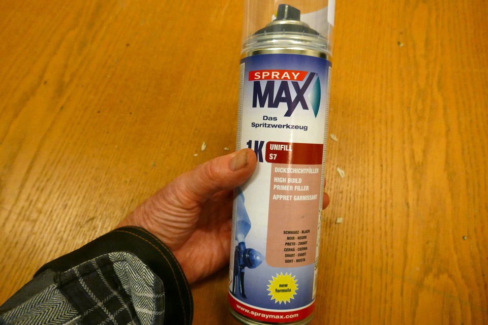
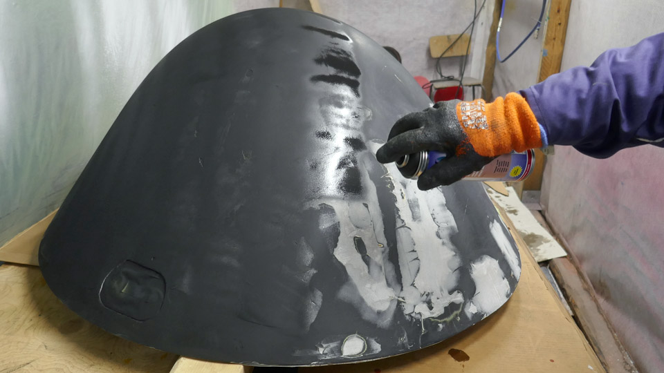
After two rounds of filling and sanding, the team decided to paint the surface with a primer. Spray MAX Primer filler was chosen, and it was purchased from the Pintaväri store. This primer fills well the small roughness on the sanded surface and it can be re-sanded and re-painted.
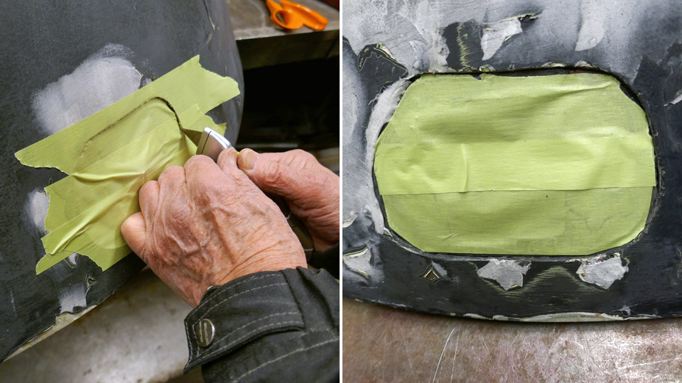
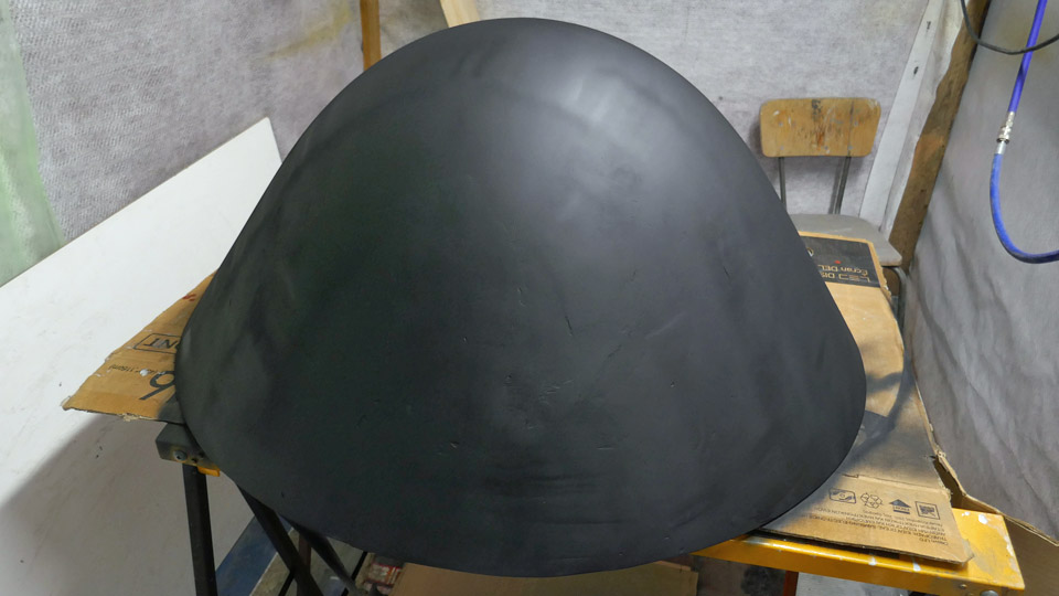
Two layers of Sprey primer were spread on the sanded radome surface. Before applying the paint, the cover holes of the radome’s fastening bolts were protected. Although the result after the primer paint looked quite good, the smooth mat black paint surface revealed some uneven areas, and we will still have to fill and sand the radome’s surface in some areas before it is completely smooth and ready for the finishing paint. Photos by Lassi Karivalo. Translation by Erja Reinikainen. |
|
Avainsanat: aviation history, restoration, Caravelle, Tuesday Club, SE-DAF |
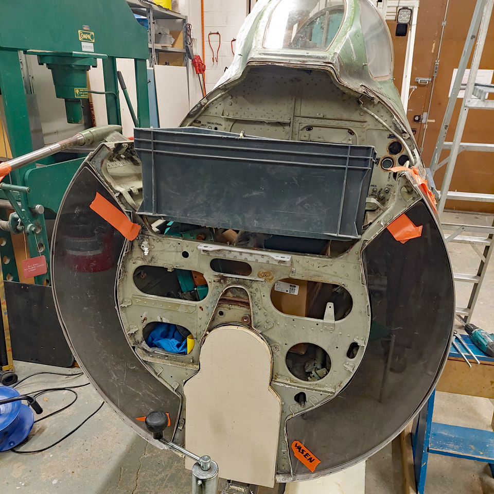
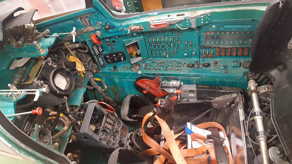
Dismantling the MG-111 cockpit interior for the simulatorMaanantai 5.12.2022 - Tuesday Club member Work on the MiG-21BIS MG-111 cockpit to transform it into an experience simulator continues at the Tuesday Club. When the MG-111 was scrapped, Aviation Museum Society Finland received a part of the fuselage, containing the cockpit, to be modified to an experience simulator. To achieve that, most of the equipment of the cockpit entity will be dismantled. In their place the simulator equipment will be installed, but part of the original equipment and parts will also be reinstalled.
Most of the wiring and equipment from the space in front of the cockpit, as well as the wiring from the bulkhead behind the cockpit, were already dismantled at the yard of the Aviation Museum. After this the cockpit part was taken to the restoration workshop of the Aviation Museum, to dismantle the equipment and wiring within the cockpit.
First the space in front of the cockpit and the rear bulkhead were stripped off the last wires and equipment racks and holders there. So both spaces are now empty. The empty front space will at its time house the simulator equipment of the MiG-21BIS cockpit simulator. The rear bulkhead will be tidied and painted and the large openings of the engine air intake channels that are visible there will be covered with plexiglass.
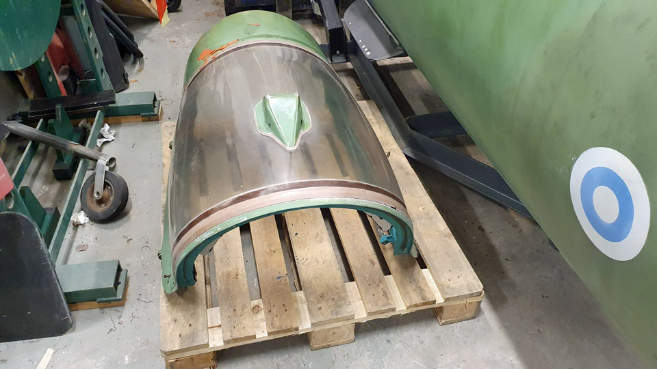
Photo: Juha Veijalainen. For emptying the cockpit of its equipment, we wanted to detach the pilot’s seat because removing the seat would provide space for working in the cockpit, both during the removing the equipment and installing the simulator equipment. Before we set to removing the seat, we detached the cockpit canopy.
Photo: Ari Aho. To remove the seat, we received expert guidance and the necessary lifting lever from the former MiG-21BIS mechanics at Rissala. Detaching the seat didn’t, however, succeed because we couldn’t find the release catch under the MG-111 seat, where it normally is. It is possible that the release catch wasn’t reinstalled when the seat was removed when the MG-111 was struck off charge and reinstalled after the detonation charges belonging to the ejection seat had been removed. Well, we’ll try again to remove the seat in December, when we’ll hopefully get a mechanic from Rissala to come and visit and ponder about the thing with us.
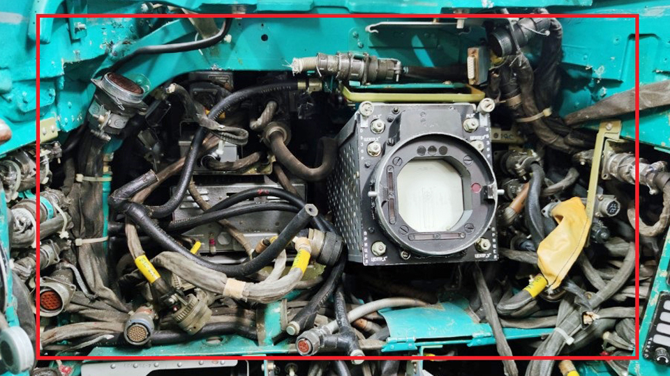
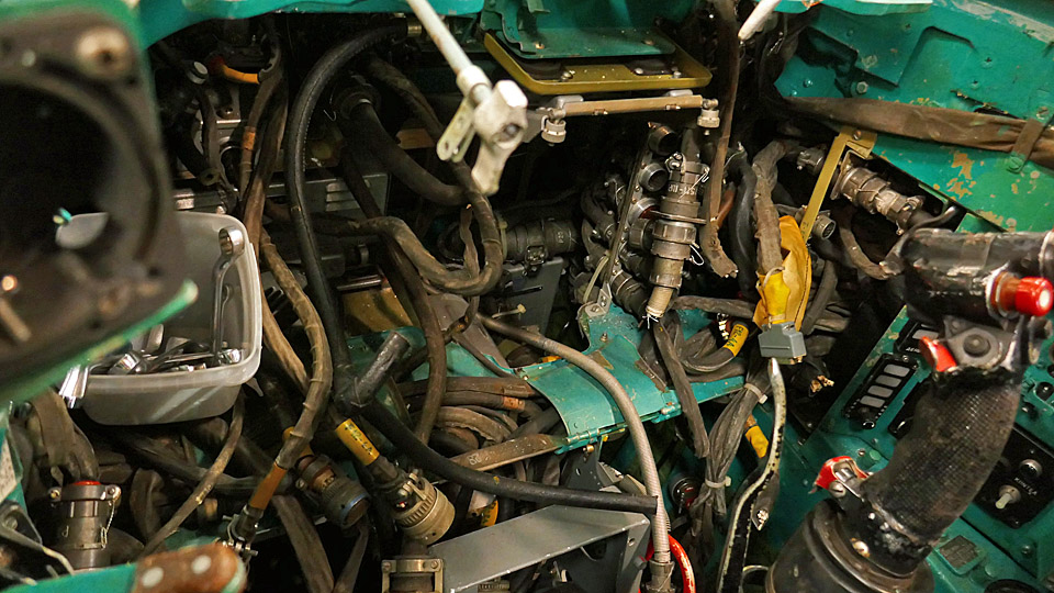
Photo: Juha Klemettinen. Although we couldn’t detach the pilot’s seat, we started to dismantle the interior of the cockpit according to Juha Klemettinen’s advice to transform the cockpit of MiG-21BIS MG-111 into a simulator. Juha removed the instrument panels and other switchboards himself. Our task was to dismantle, as advised by Juha, the space behind the instrument panel of the radar screen and the numerous wires criss-crossing there. How on earth could there be so much wiring!!
We started the work on the cockpit first by removing the radar and then turning our attention to the wires. It wasn’t so much about single wires, but bunches of wires inside a skin. Some of them could be disconnected from their connectors and removed. Disconnecting the wires from their connectors was awkward, because the connectors were either hidden on unobtainable. It came to mind that our Russian colleagues hadn’t paid a thought to easing the work of mechanics when positioning the wires.
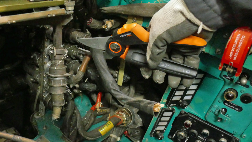
At the end there was no other option left but to cut the wires. Juha gave us permission to do that. Cutting the thick wires was no mean feat, because the thick bundles containing many wires were very tough nuts to cut.
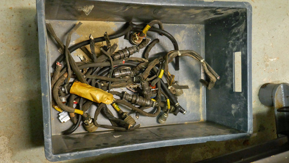
Someone had the bright idea to acquire a pair of Fiskars garden secateurs (branch cutters) to cut the thick bundles of wire. If the Fiskars secateurs cut 20-30 mm thick branches easily, they should cut through the Russian wires. So we bought a pair of Fiskars branch cutters and they worked very well in cutting the wire bundles. The box containing cut off wires began to fill with wires of various length removed from the cockpit. We still have our work cut out for us before the space behind the instrument panel has been completely emptied.
Simultaneously, as we worked inside the cockpit, we dismantled the multi-pin connecting plugs that ran through the bulkhead between the cockpit and the space in front of it. The shackles that fastened the plugs to the bulkhead could be turned open. After that the plugs were pushed through the bulkhead, to the cockpit, to be drawn out from there. It wasn’t possible to push them into the cockpit very much, because the thick wires didn’t yield. It will probably be possible to remove the plugs with their wires, after a sufficient amount of wires have been removed from the cockpit. In good time the wires from the simulator mechanism will be drawn through the openings in the bulkhead between the cockpit and the space in front of it, where the simulator equipment will be installed. Photos: Lassi Karivalo except if otherwise separately mentioned. Translation by Matti Liuskallio. |
|
Avainsanat: aviation history, restoration, Tuesday Club, MiG-21BIS, MG-111 |
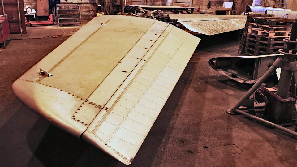
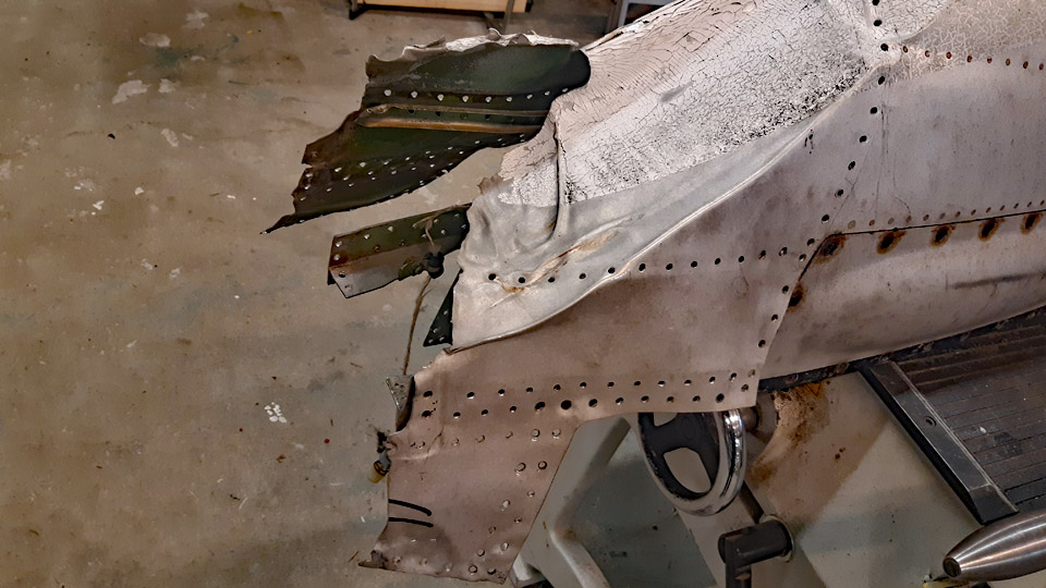
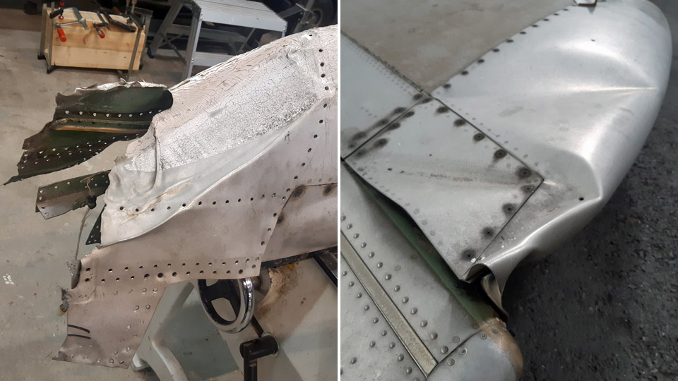
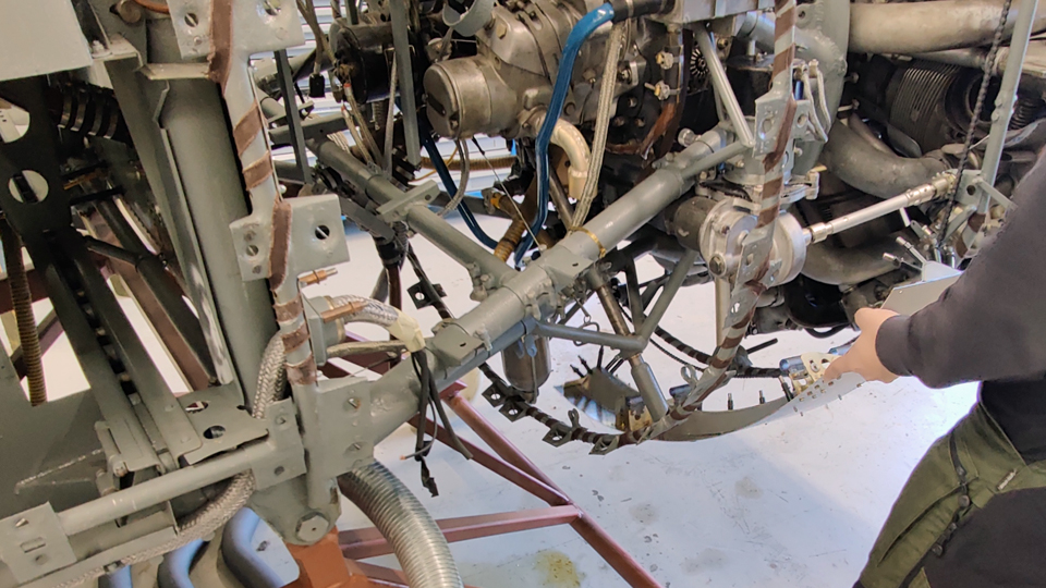
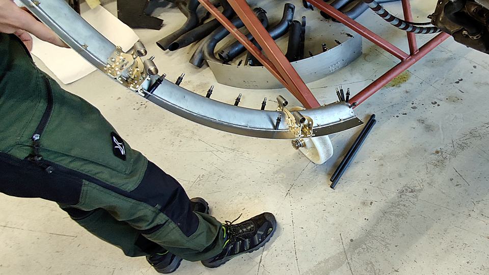
The repairing of the Caravelle's right wingtipMaanantai 21.11.2022 - Tuesday Club member The right wingtip of the Caravelle III (SE-DAF), which was acquired from Sweden by Aviation Museum Society Finland and is now in a hall in the Pansio port area in Turku, has been badly damaged at its leading edge. The damage has been caused by some airport vehicle which has hit the Caravelle’s wingtip during the decades when the aircraft stood on the side of the airfield. There is a dent also in the middle of the tip of the left wing. Furthermore, the trailing edge of the horizontal stabilizer tip and the radome at the nose of the aircraft have been damaged in collisions. The wings, the horizontal stabilizer and the radome will be repaired at the Tuesday Club.
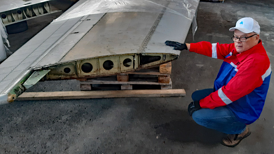
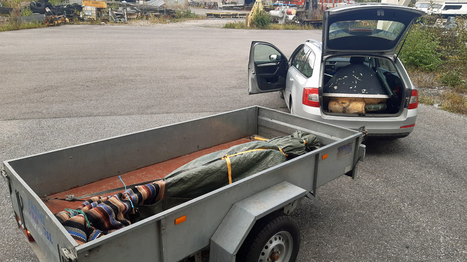
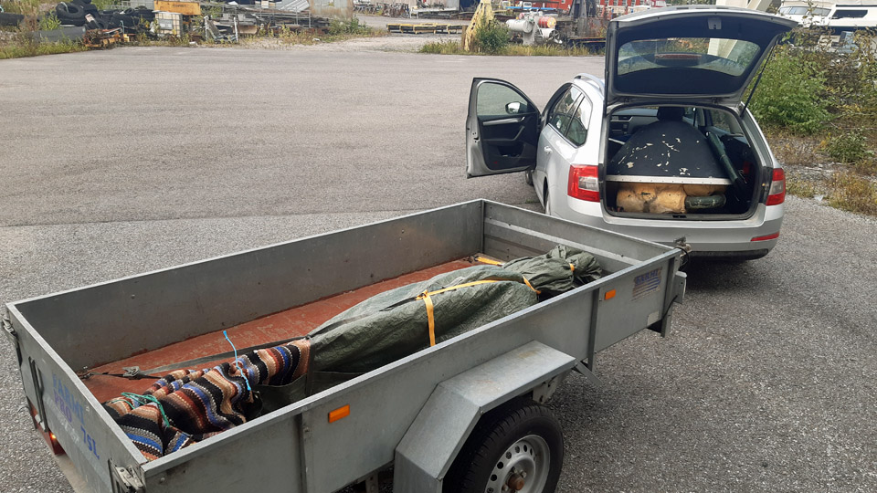
Fortunately, the tips of the Caravelle’s wings and the horizontal stabilizer can be detached. The Aviation Museum Society’s volunteer team in Turku detached the wing tips, the damaged tip of the horizontal stabilizer and the radome to be taken to Vantaa. These parts were brought from Pansio in the boot of a car and on a trailer to Vantaa, to be repaired at the Tuesday Club.
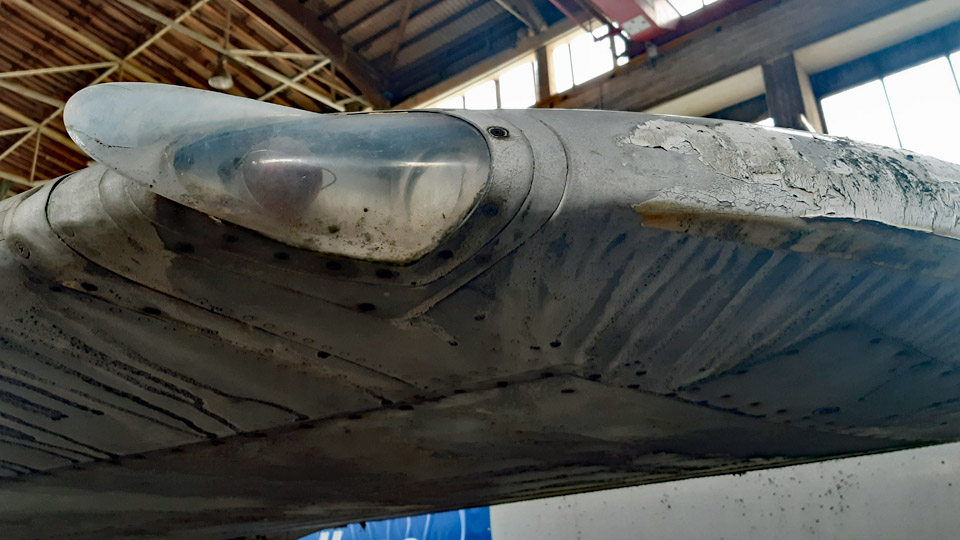
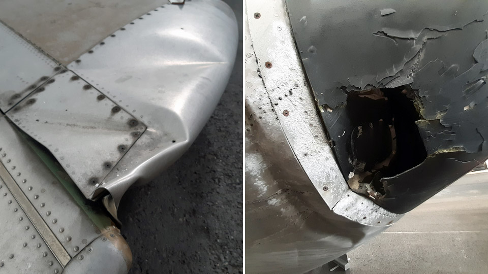
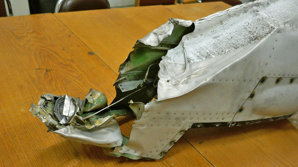
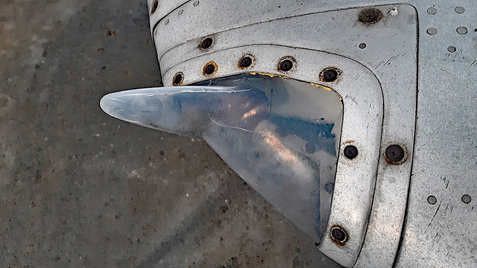
The leading edge of the right wingtip is broken along a distance of 40 cm. The navigation light and its uniquely shaped lamp shade are broken too. The navigation light shade on the left wing is unbroken. When repairing the right wingtip, the left wing will be used as a model.
The navigation light is badly broken. It may be possible to make a new lamp socket for the light bulb, but it will probably be impossible to make the navigation light shade which has a complicated shape. It can hardly be found as a spare part, either. Well, we can surely ask Le Caravelle Club in Sweden, they have restored a former SAS Caravelle.
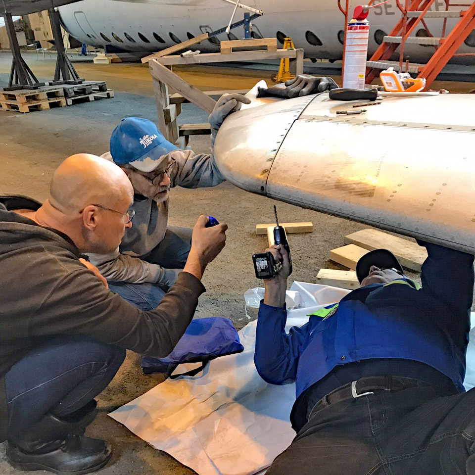
The repair of the right wingtip was started by drilling out the rivets which fastened the crumpled aluminium sheets on the wingtip. After this the sheets could be bent open, and we could get a better view of the damaged tip’s structure.
We tried to mould the damaged aluminium sheets and see if they could be bent into their original shape. However, the duralumin sheets on the wingtip are made of such hard aluminium that they broke when they were bent back into their original shape. We had to admit that the damaged wingtip can’t be repaired by using the original sheets. The wingtip and its supporting structures will have to be rebuilt from new aluminium sheets. Fortunately, we have the unbroken tip of the left wing to use as a model. We dismantled the whole damaged area of the right wingtip.
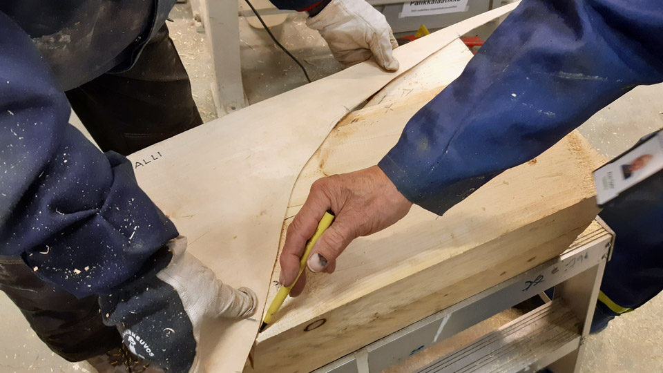
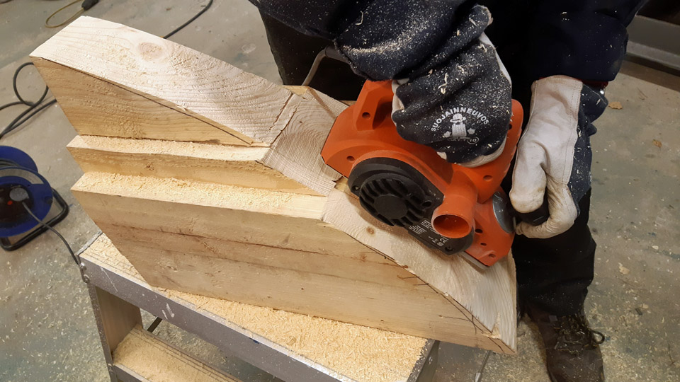
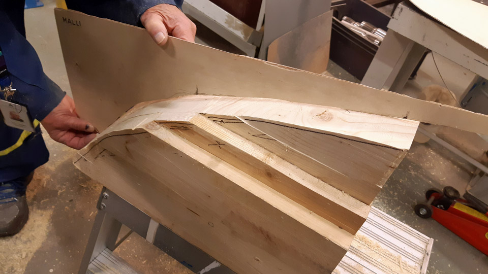
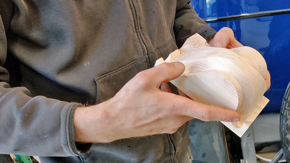
We analysed different alternatives for building the right wingtip and concluded that the broken part will be rebuilt from several sheets of aluminium, which are moulded into the shape of the wingtip and riveted together. For this purpose, a wooden last will be made, shaped as the unbroken left wingtip, but its mirror image. Each sheet of aluminium will be bent into shape against this last and then riveted to each other to form the new wingtip. Before riveting, a new supporting structure for the wingtip will have to be built.
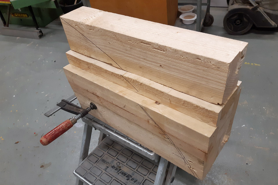
We started to build the wooden last by gluing together some pieces of plank to make a piece of wood, larger than the wingtip. This piece of wood will be gradually shaped by sawing, carving, planing, and grinding to match the shape of the wingtip’s leading edge. To make the piece of wood exactly match the shape of the wingtip, profile jigs, made of plywood and shaped as the unbroken wingtip, will be used. When the shaping progresses, the profile jigs will be used for testing where the wooden last still needs to be shaped.
When the glue had dried, we could start shaping the chunk of wood into the wooden last. First the curved side profile of the wingtip was drawn on the piece of wood. A band saw was used for sawing along the drawn line and almost one half of the piece of wood was cut off. Then the shaping continued with a hand milling machine and a plane. When the shaping work is continued, the shape of the last will be checked with the profile jigs. There is still a lot of work ahead before the wooden blank matches the shape of the wingtip’s leading edge and can be used as a last for moulding the aluminium sheets for the broken wing. Photos by Lassi Karivalo Translation by Erja Reinikainen. |
|
Avainsanat: aviation history, restoration, Caravelle, Tuesday Club, SE-DAF |
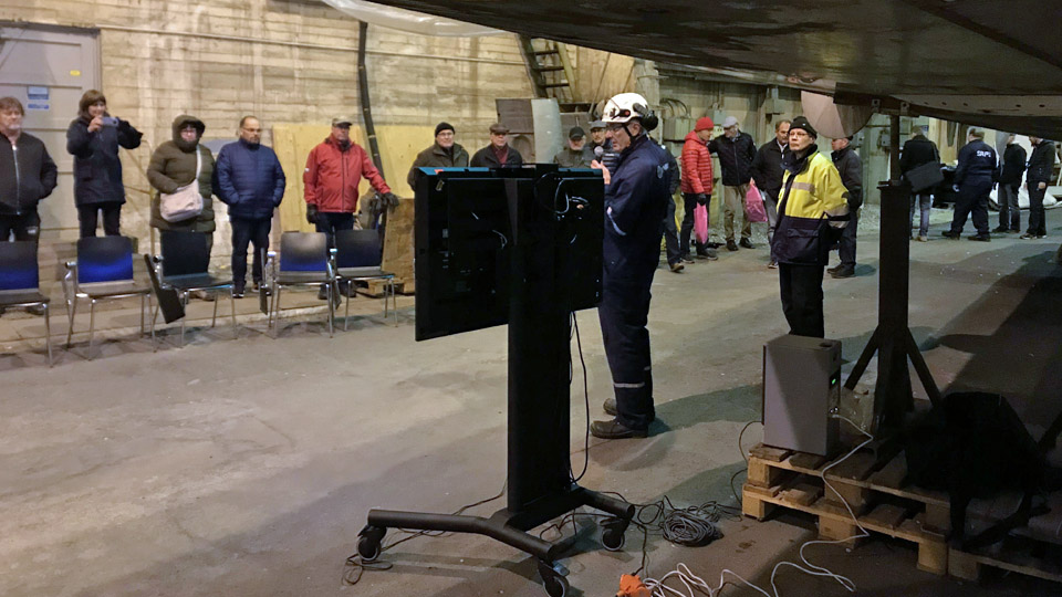
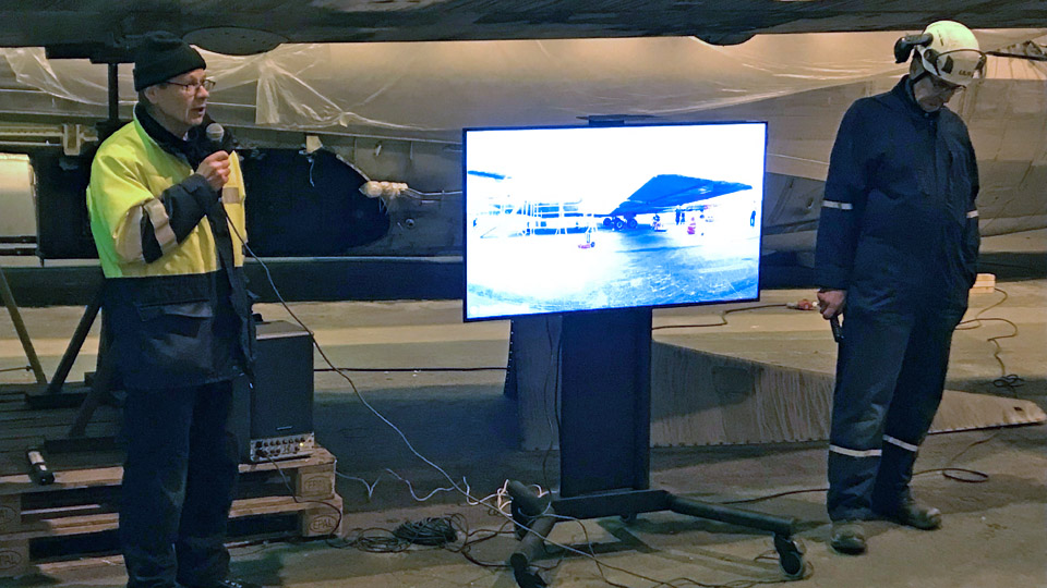
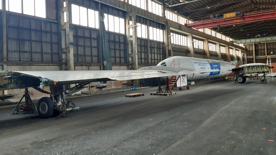
Open Door Evening in the Caravelle hall in Pansio on November 17th, 2022Sunnuntai 20.11.2022 On Thursday, November17th we had an evening of open doors in the Caravelle hall. After the fuselage had been upright, access to the cabin and cockpit was possible. We wanted to arrange an event for the stakeholders, other near-by companies, and everybody else interested in the project, where we would tell the visitors about the progress and next steps of the project.
Event was opened by Janne Salonen, the chairman of Aviation Museum Society Finland. After him the progress of the project was presented by our experts Markku Ahokoski and Martti Saarinen. After the presentations the participants had an opportunity to walk around in the hall and see the parts of the aircraft and take pictures.
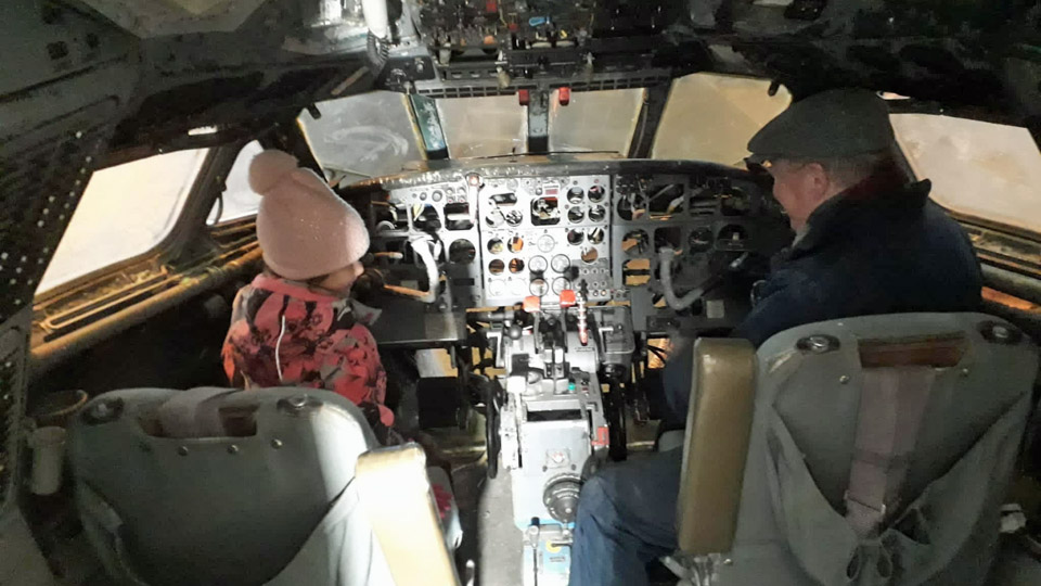
Especilly the cabin and cockpit were point of interests to the visitors. Hannu Hedman from the Turku Caravelle team showed the cockpit to his granddaughter Olivia. She was seated on the captain’s seat to test what it would be like to fly, and the lack of major parts of the cockpit instruments didn’t bother her at all. Autumn is turning into winter and the weather in Pansio was around freezing point. Despite the cold weather, nearly a hundred visitors were present. The Turku garrison’s military canteen had a van at the site and the visitors could enjoy doughnuts and coffee. There was also a possibility to barbecue sausages. Possibly because of the weather, the van was a popular spot.
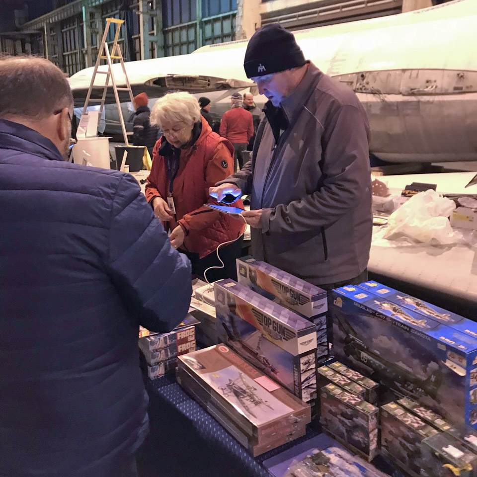
Aviation Museum Society had also arranged a small sales desk where Caravelle material and different kinds of aviation material from scale models to aviation history books was available. Maybe due to the coming Christmas season the material sold well. The couple of hours of open doors passed quickly and when the night was closing, the organizing team switched off the lights and closed the doors. We thought the event was a success and the public awareness of the project was increased considerably. Text and photos by Ismo Matinlauri. Translation by Erja Reinikainen. Aviation Museum Society has a permission to publize third photo on behalf of both persons. |
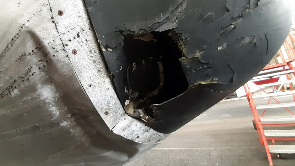
The repair of the Caravelle III (SE-DAF) radome has been startedLauantai 12.11.2022 - Tuesday Club member The Caravelle III, owned and brought from Sweden by Aviation Museum Society Finland, is stored in a hall in Pansio port area near Turku. There it is being restored before placing it on display at Turku airport. In Turku the local volunteer team is working on the restoration, which started with cleaning the aircraft’s surfaces before painting. The Tuesday Club has been given the task to repair the damages which have been caused on the aircraft during its long storage period. There is damage on e.g. the right wing-tip, the left tip of the horizontal stabilizer and the radome on the aircraft’s nose. We just can’t help wondering which airport vehicle at Arlanda has managed to bump into the Caravelle so many times.
Annoyingly, the damage caused by the collision on the radome happens to be right on one of the hatches which cover the fastening bolts of the radome. The radome, made of glass fibre, has bent inwards at an area of about 20x15 cm. The collision has also broken the edge ring of the radome and damaged the rim of the bulkhead on the aircraft’s nose, under the radome. There is also damage on the aircraft’s nose under the bulkhead edge, the metal edge of the nose is bent, and the aluminium covering is creased. The painted surface of the glass fibre radome is also badly flaking.
The Turku team disassembled the damaged tips of the right wing and the left horizontal stabilizer and the nose bulkhead, with its radar and radome. We fetched the bulkhead and the tips of the wing and horizontal stabilizer from Pansio to be repaired at the Finnish Aviation Museum in Vantaa. The repair of the radome and the wing tip are well under way, the tip of the stabilizer will be repaired later.
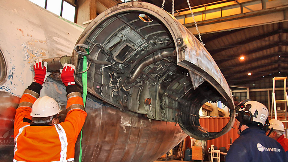
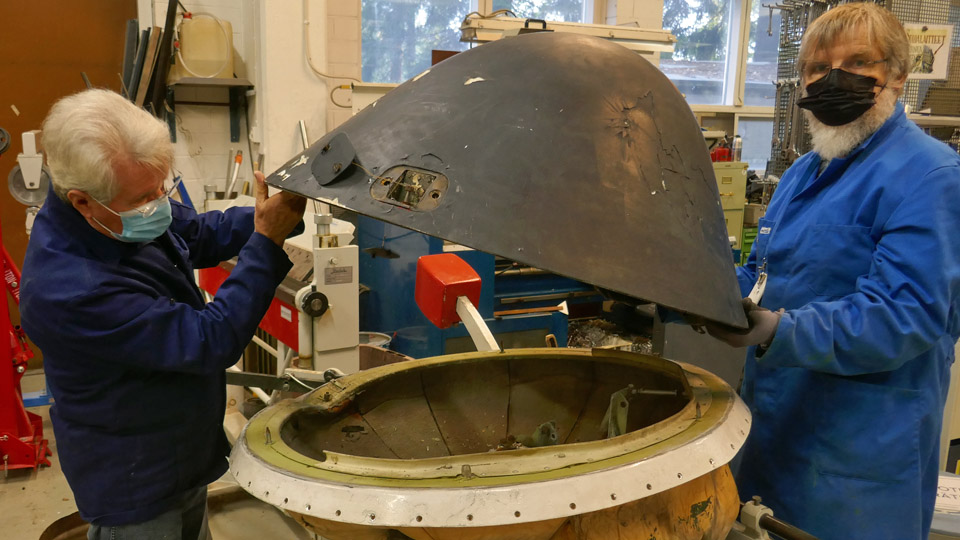
Before repairing the radome, it had to be disassembled from the nose bulkhead. The radome is fastened on the bulkhead rim with three fastening bolts and three guide pins. The bolts can be seen when the hatches on the radome, one above each bolt, are opened. First the hatches above the two unbroken fastening bolts were opened. Under each hatch a supporting frame could be seen, it is fastened on the radome glass fibre and on the radome’s metal edge. There is a crown-headed fastening bolt in the middle of the frame. The two bolts on the edge could be easily opened and unfastened from the threaded sleeve on the metal rim of the bulkhead. Fortunately also the bolt under the damaged hatch could be opened and after this the radome could be lifted from the bulkhead. We could now see that the radar space under the radome was empty. The radar had been disassembled at some point during the Caravelle’s storing period, but obviously before the radome was damaged.
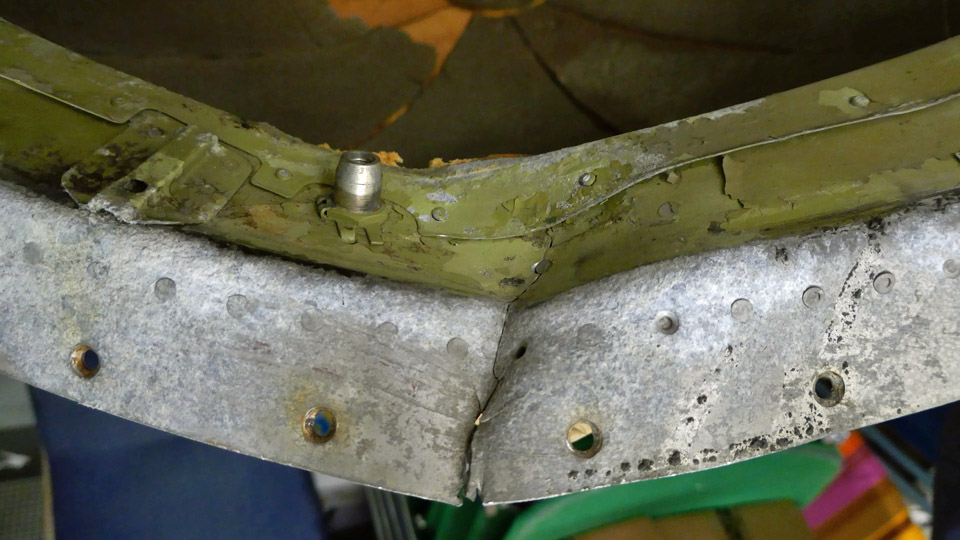
When the radome had been disassembled, we could see the damage on the bulkhead’s metal rim, under the radome’s edge. The bulkhead rim is badly bent inwards and broken. It must be repaired before the radome can be assembled back into its place after repair.
Photo: Reijo Siirtola
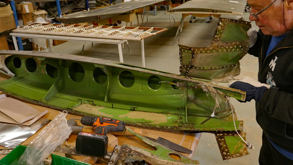
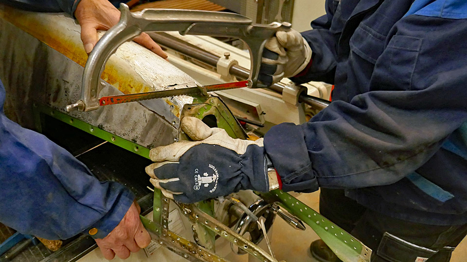
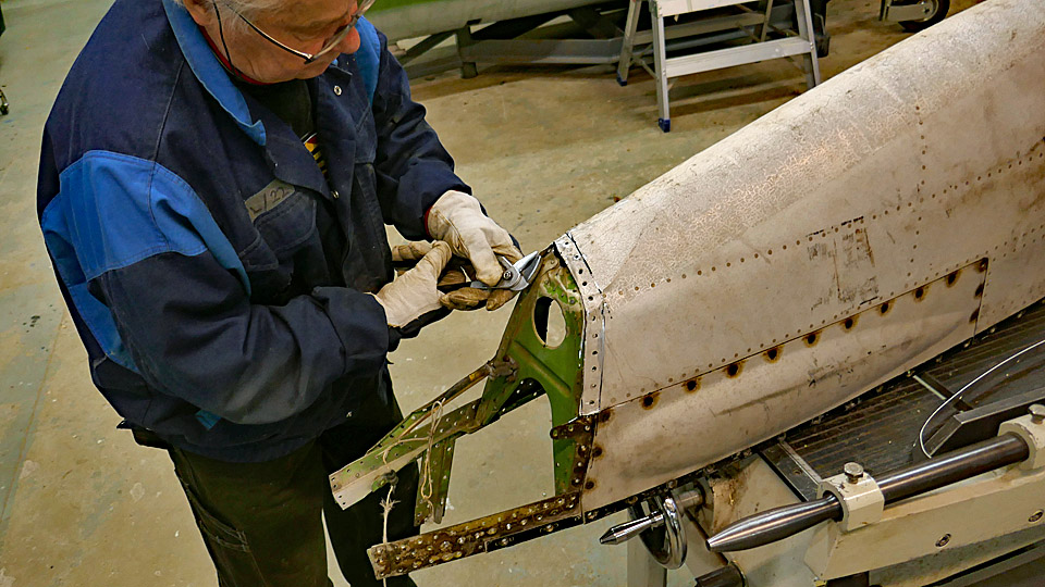
As a preparatory task before repairing the glass fibre radome, the damaged metal frame of the fastening bolt was disassembled. The metal frame has been tightly riveted on the damaged edge of the radome, we didn’t even try to unfasten it in other ways than just by cutting through the radome’s metal edge on either side of the bolt’s frame. The broken area of the radome could now be removed together with the bolt frame.
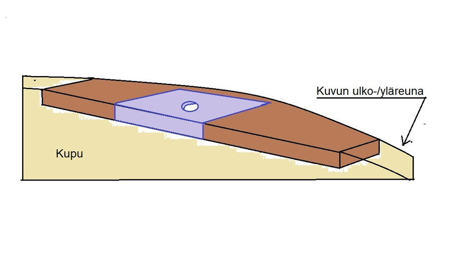
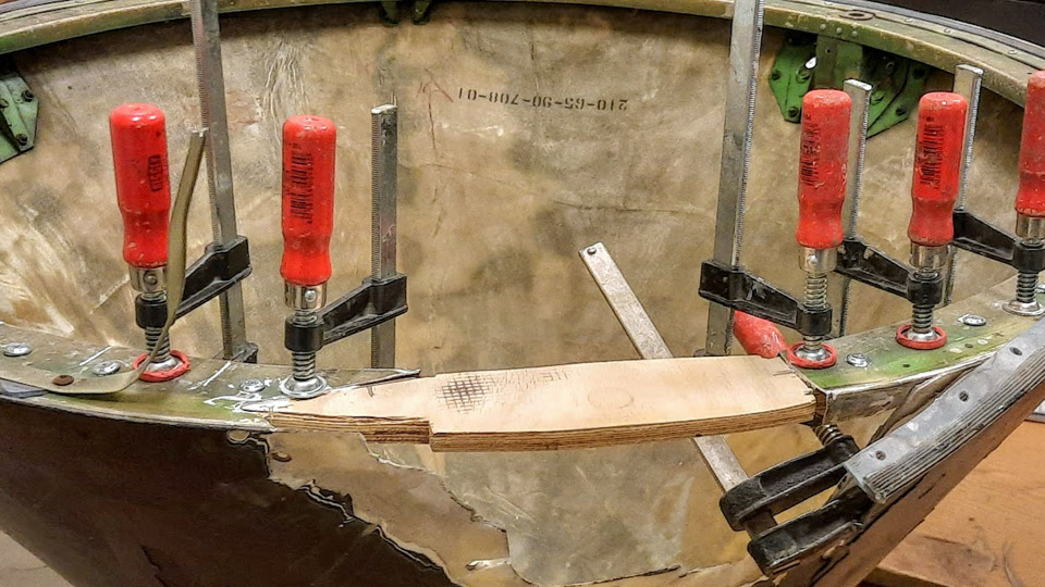
Photo: Reijo Siirtola. The repair plan is to first build a replacing piece for the removed section of the radome’s metal edge. The broken metal frame for the bolt can’t be used any more, so we came up with a solution where a bridge between the radome’s cut edges will be made from strong plywood. The third radome bolt can be fastened on the threaded sleeve on the bulkhead’s rim through the plywood bridge. A metal collar for the bolt will be inserted on the hole on the plywood. This repaired joint of the third bolt will not be as strong as the original, but it will be quite ok for the radome of a non-flying display aircraft. From outside the difference won’t be seen.
Photo: Reijo Siirtola. When the radome’s cut edge has been repaired in the way described above, a sufficient number of glass fibre fabric layers will be laminated with epoxy resin on the collision hole on the radome. The laminated area will be ground to match the level of the dome’s original surface. A hole for the bolt hatch will be made into the laminated surface.
We started to build the piece missing from the radome’s metal edge. A piece of strong plywood was cut, imitating the shape of the missing edge piece. The piece of plywood was glued with epoxy glue as a bridge between the ends of the metal edge. There is still some work needed before the bridge is ready. After that we will laminate the hole in the radome. The edges of the damaged area in the glass fibre dome have already been ground thin for the laminating work. Photos by Lassi Karivalo except if otherwise mentioned. Translation by Erja Reinikainen. |
|
Avainsanat: aviation history, restoration, Caravelle, Tuesday Club, SE-DAF |
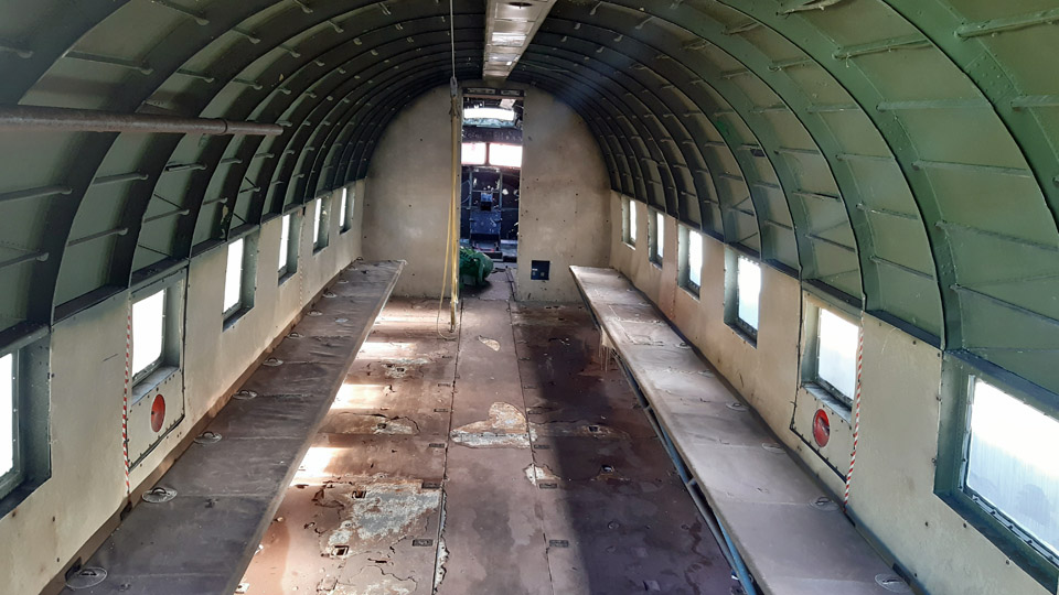
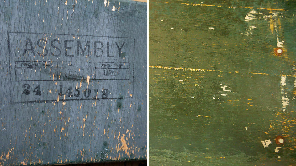
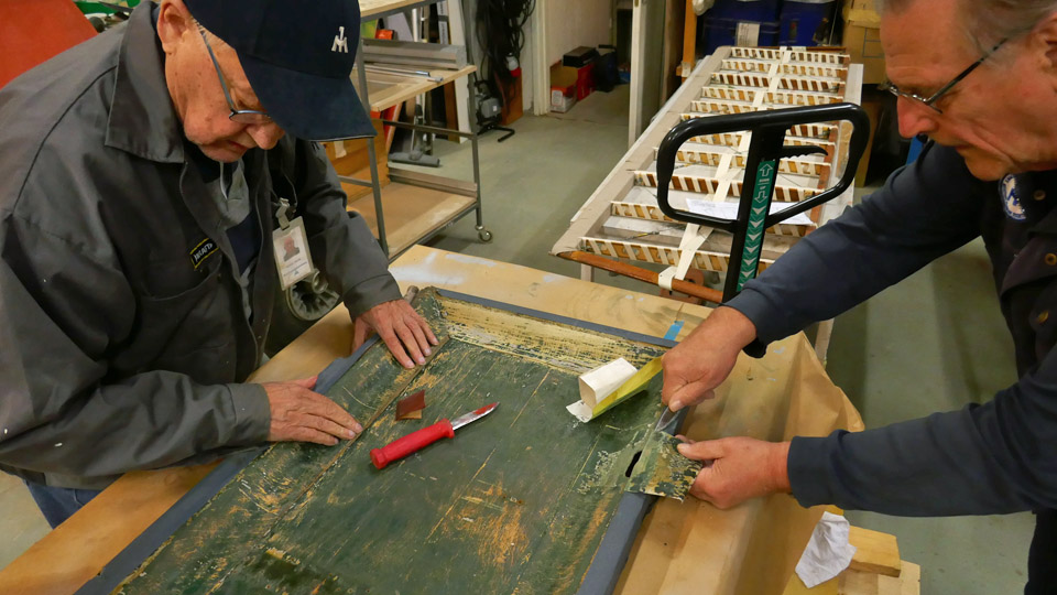
DO-5's door from the cabin to the cockpit is under restorationSunnuntai 6.11.2022 - Tuesday Club member The restoration work of the DO-5 (DC-3/C-47) fuselage, owned by Aviation Museum Society Finland, is now concentrating on the wooden door which separates the cockpit from the cabin. Structurally it is a so-called panel door. The painted surface on the cockpit side is badly worn and flaked, and it will be restored to its original condition. On the cabin side the original surface of the door has been hidden under a modern and pale hard-surfaced board. The same board has been used for covering the cabin side of the wall separating the cockpit and the cabin, and the cabin walls up to the upper level of the cabin windows. We are wondering whether the door and walls have been re-covered during the aircraft’s Lufthansa period or when it came to the use of the Finnish Air Force. We decided to leave the cabin side of the door as it is, with its new covering, to match the cabin walls. Judging from the cockpit side of the door, the door seems to be an original C-47 type door. An indication of this is a large stamp found on the plywood surface of the door. The word ASSEMBLY and serial number 24 145018 can still be read on it. There are also other numbers on the stamp, but they are not clearly distinguishable.
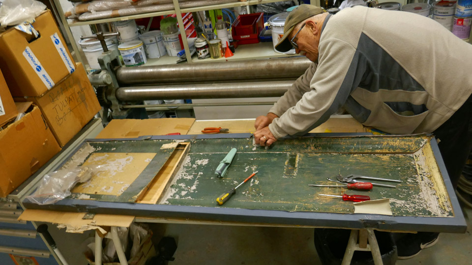
For restoring the door, it was disassembled from its frame and brought to the restoration workshop at the Finnish Aviation Museum. The painted surface on the cockpit side will be sanded and the plywood veneers, which have delaminated, will be glued back together. Finally the door will be repainted.
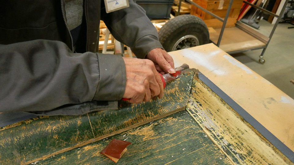
Before painting, the loose flaked paint was scraped off and the greenish grey paint surface was sanded smooth. Our aim is to paint the door and the aluminium wall surfaces in the cockpit using the original shade of green. Before that we will try to find out what the original paint and its shade might have been.
At least two different shades of green can be seen on the door. It looks as if there is a paler shade of green underneath, and it has been covered with a darker green paint. On the aluminium wall surfaces in the cockpit at least three different shades of green can be distinguished. We can only guess which of these could have been the original one – if any. After the invasion of Normandy, the DO-5 has been in civilian use in the Netherlands, French Indochina, and Germany before coming to the service of the Finnish Air Force in 1960.
I asked for advice about the DC-3 colours from the Finnish Air Force Museum. I learned that the cockpit colour, and also the colour of the door, was most likely the American “Bronze Green” or “Dull Dark Green”. In the American aircraft of that era the colour of the inner surfaces was usually dark green. Zink chromate anti-corrosion primer was used on aluminium surfaces and its shade was modified with black pigment, adding some UV-protection on the paint. However, there are still some issues to resolve before we can go and buy the paint.
The surfaces still need some preparatory work before the door is ready to be painted. We haven’t yet decided whether the door will be painted now or in the spring, together with the aluminium wall surfaces in the cockpit.
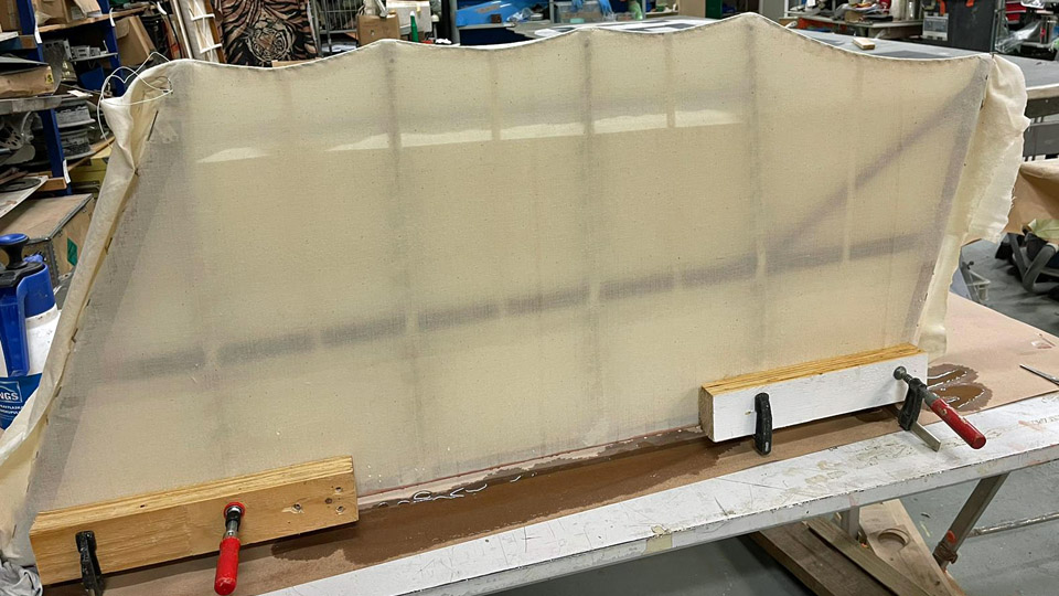
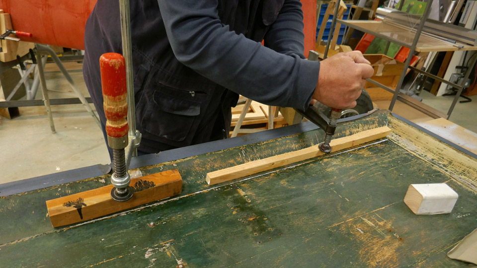
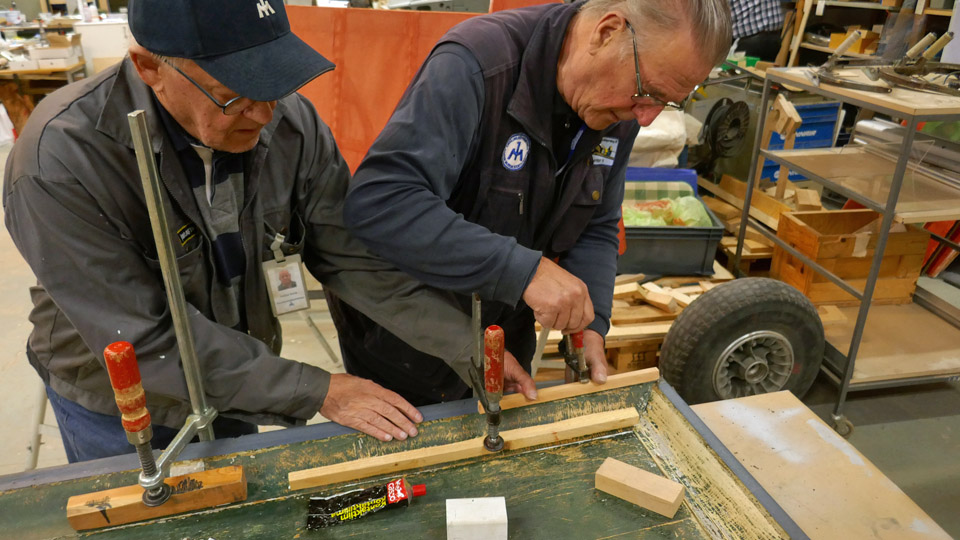
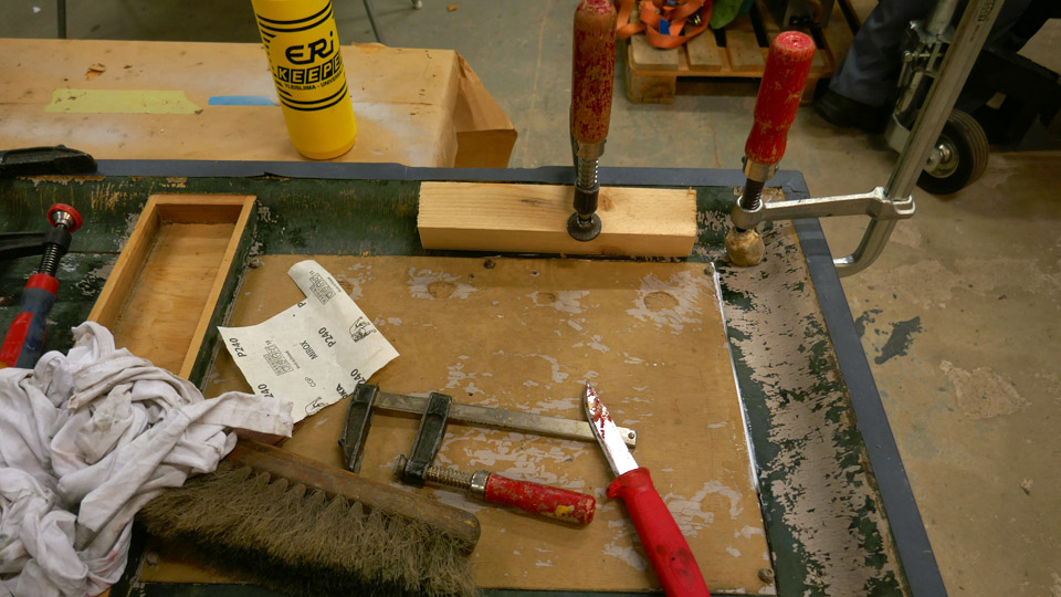
When the door surfaces had been sanded, the delaminated plywood veneers were glued into place. The veneers were pressed tightly against the surface using blocks of wood and clamps. The glue we used was EriKeeper Plus wood glue, meant for outdoor use. Photos by Lassi Karivalo Translation by Erja Reinikainen. |
|
Avainsanat: aviation history, restoration, Tuesday Club, C-47, DC-3, DO-5 |
Restoration of Caravelle in progressSunnuntai 23.10.2022 - Ismo Matinlauri In October the restoration of the Caravelle started in earnest when about 15 active and enthusiastic volunteers from Turku and its surrounding started getting together every Tuesday and Thursday afternoon. Usually there are 6 to10 active members simultaneously at work in the rented port hall, so the work is progressing well and efficiently. Furthermore, a couple of times we have been there also on Sundays, wrapping up the week’s work. The target for this autumn – before the cold winter season is here – is to get the aircraft’s fuselage turned upright, now it is still in the transportation position and tilted 45 degrees. Turning it is necessary to get the cabin door open and have a quick look inside.
Before straightening, we aim to benefit from the current fuselage position and restore the bottom of the fuselage where there are areas of old paint. They have now been washed and sanded, and our aim to paint them first with a primer and then test two different kinds of topcoat paints, grey and aluminium in colour. They are meant to simulate the original aluminium surfaces of the aircraft. We shall then choose the more suitable one to paint the parts of the wings, which won’t be polished.
The scratching, grinding, and painting of the base of the tail fin, reinforced with glass fibre, is also easier when the fuselage is in its current position. Here we will test the white topcoat paint, which will be used on the upper part of the fuselage as defined in Finnair’s original painting scheme. Teknos two-component paints and colour codes to be used are the following:
The painting work requires minimum +5...+10°C outdoor temperature. This means that now we are approaching the limit where the unheated port hall is too cold for painting. The next step in the restoration work is the polishing of the unpainted parts of the fuselage and the leading edges of the wings, but more about that in the next blog. Photos by Ismo Matinlauri Translation by Ismo Matinlauri & Erja Reinikainen |
|
Avainsanat: aviation history, restoration, Caravelle |
DO-5 cockpit seatsTorstai 20.10.2022 - Tuesday Club member Suomeksi Restoring the fuselage of the DC-3/C-47 (DO-5) into at least tolerable condition before display requires all kinds of work. The main emphasis is on the cockpit area.
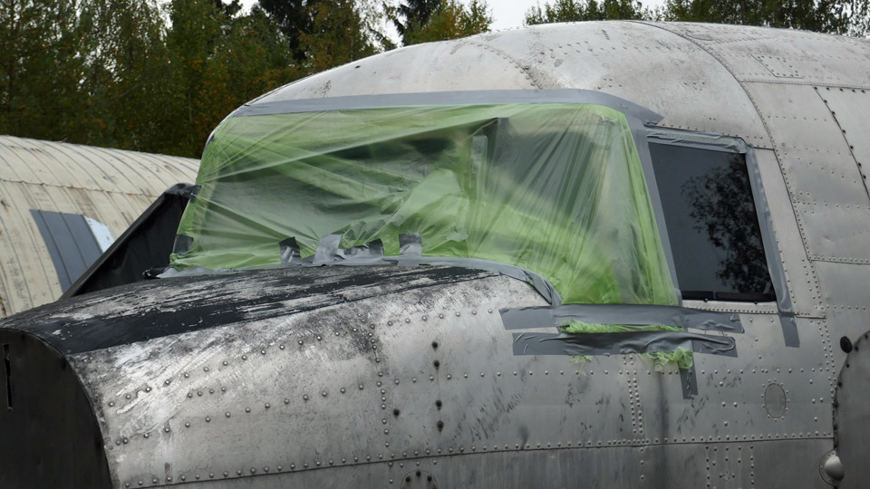
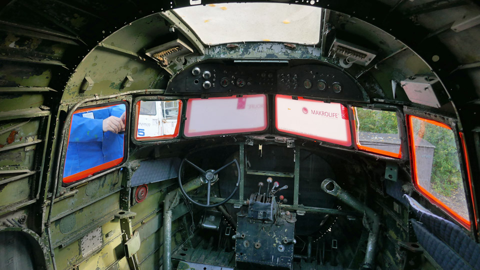
When the tail sections of the DO-5 and other clobber had been moved from the fuselage into the storage container next to the aircraft and when the cockpit windows had been sealed to prevent rainwater from entering the aircraft, we could concentrate on the cockpit. The starting point was a complete disaster area: the instruments and most of the cockpit equipment were missing, the seats were tattered, the walls bare without interior panels, and there was rubbish everywhere.
Our first step was to clear the cockpit of the clobber and rubbish, which had filled it during the years. Eventually we were even able to use a vacuum cleaner for cleaning the surfaces in the cockpit. The first aim is to make the cockpit look tidy. Thinking further, it would be nice to install some of the missing instruments and equipment back into the cockpit, but now this seems to be very far away.
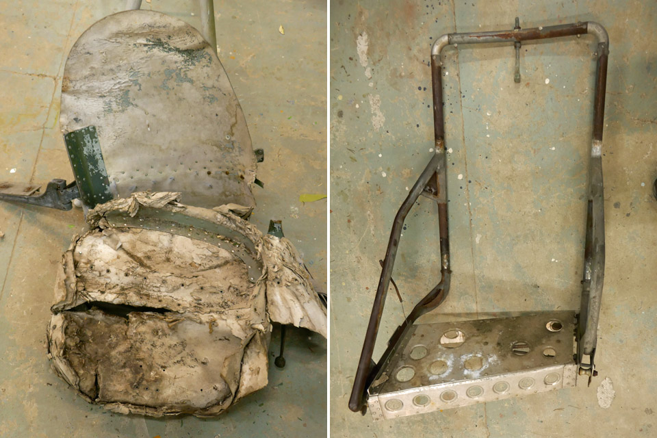
After cleaning our following targets were the pilots’ seats. The seat consists of the actual seat and its tube frame, on which the seat is fastened. Our aim is to restore the seats although the seat parts are badly damaged. The tube frames are still in good condition, although covered with rust.
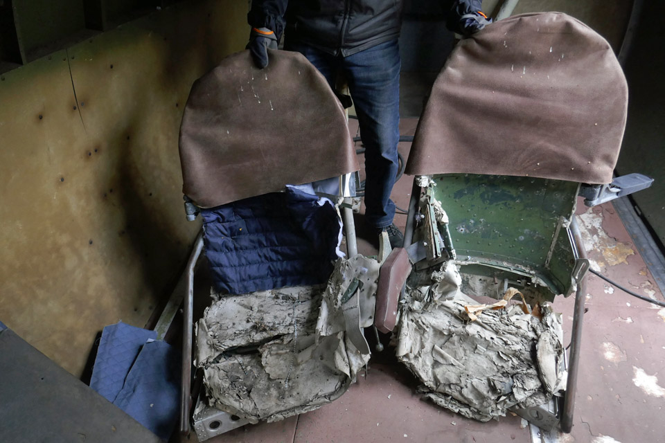
The reason for the damage is that the whole seat part is made of multi-layer cardboard; pressed and stiffened into the shape of a seat. Due to the rainwater and humidity which has got into the cockpit, the pressed cardboard has become soggy, and the cardboard layers have disintegrated into pulp. However, the seat backs are still in reasonable condition.
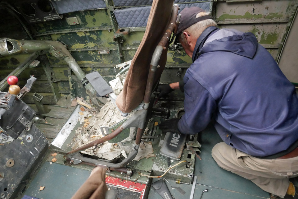
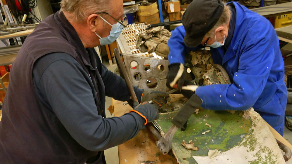
The truth is that it won’t be possible to restore these original tattered seats into good condition. The seat part of both seats will have to be completely replaced, even though the seat back is still useable. We will certainly be stuck between a rock and a hard place, trying to figure out how the seat part could be rebuilt. One option would be to build it from aluminium plate, this is an alternative to be considered. The seat frame must be cleaned of rust and painted.We started the seat work by unfastening both pilot’s seats from the rails on the cockpit floor. Then the seat part of each seat was unfastened from the seat frame. The seat is fastened on the seat frame tube with brackets, which slide on the tube to allow the height of the seat to be adjusted. The seat is locked at the suitable height with lock pins which are pushed into the holes on the frame tubes. The adjusting mechanism is under the seat.
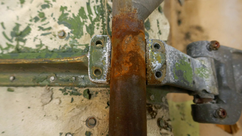
We started the dismantling work of the seat on the left. We unfastened the rusted brackets around the seat frame tube to disassemble the seat from the frame. This wasn’t easy, because the seat height adjustment locking pins were still firmly stuck in their holes on the seat frame. Some effort was needed before the adjustment system’s locking pins could be pulled out of their holes and the seat and its frame disassembled.
We dismantled the seat on the right in a similar way. It is identical to the seat on the left, but its mirror image. There we had to disassemble completely the seat height adjustment mechanism before the locking pins could be pulled out of their holes on the seat frame. Then the seat and the frame could be unfastened from each other. Both seat parts were taken to the DO-5 storage container to wait for further actions. Photos: Lassi Karivalo Translation: Erja Reinikainen. |
|
Avainsanat: aviation history, restoration, Tuesday Club, DO-5;DC-3, C-47, Dakota |
Working on the gills at TikkakoskiMaanantai 17.10.2022 - Reino Myllymäki When the transporting of ace Kyösti ” Kössi ” Karhila’s war trunk from Katajanokka to the Air Force Museum at Tikkakoski was added to the trip to Mikkeli, the opportunity offered itself to go and visit the Museum restoration shop to see and discuss the Myrsky restoration with the assistant conservator Antti Lappalainen. The main switchboard has been under work lately (of which there’s been a blog) and the engine radiator gills. They were, of course, rather an advanced construction because they moved lengthwise with the fuselage, without adding drag when deployed. According to historical documents the idea was taken from the gills of Junkers Ju-88, although in this bomber the gills opened outwards, at least according to photos.
Of the Myrsky gills mainly parts of the gill actuating motor and some bearing housings have remained, in other words much has been done and must be done as neo production. A big entity are the actual gill plates, which superficially seem simple, but are rather complicated entities.
The gill mechanism, that leans on the cowling support frames, works so that the gill motor transforms the rotating movement through an axle and chain to screws, which when rotating move the gills lengthwise on their axles. The gills can be left in any position between their fore and after positions.
The gills are rather ”interestingly” shaped by the machine guns. In the photo carpenter/artisan Mika Rautasaari holds in his hand a mould or last of a gill that was milled out of wood in the spring. Based on this mould the part of the gill by the machine gun will be made. The final stretch in the restoration of MY-14 is looming on the horizon. Translation: Matti Liuskallio. |
|
Avainsanat: aviation history, restoration, MY-14, VL Myrsky |
DO-5 cockpit windscreens to winter proof conditionSunnuntai 16.10.2022 - Tuesday Club member Work on the fuselage of the DC-3 (C-47) DO-5, owned by Aviation Museum Society Finland, have started promisingly at the Tuesday Club. At the moment we aim to concentrate on tasks that are possible to do regardless of the weather during the cold period and winter season. The fuselage is out in the open at the yard of the Finnish Aviation Museum. Furthermore, we have prepared the fuselage, which is out in the open, for the autumn rains and the blizzards of winter.
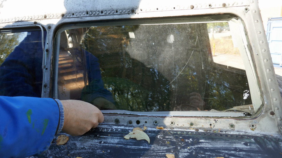
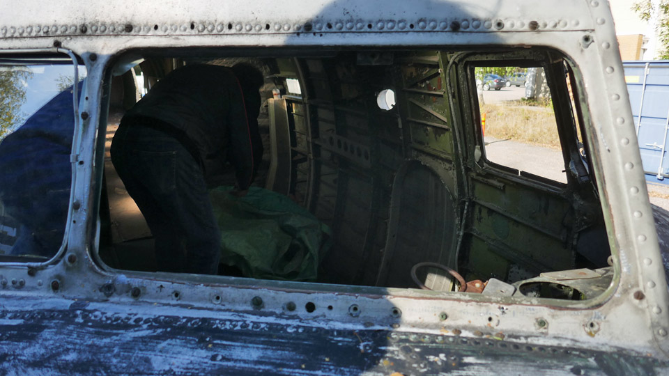
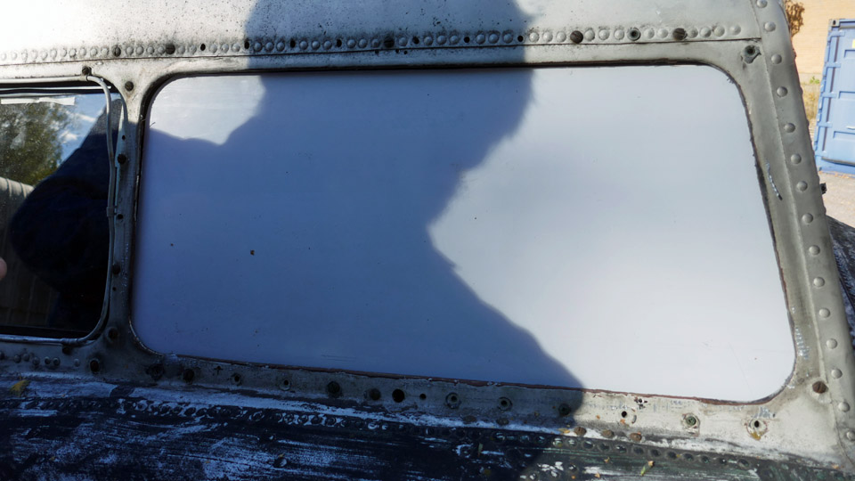
One such measure was to get the cockpit windows sealed so that rainwater and snow wouldn’t get into the cockpit. We had already earlier in the autumn covered the cockpit windows of the DO-5 with rainproof plastic, because the plexiglass panes fixed to the frames of the windscreens were too small to keep water out of the cockpit. Both the original windscreen panes of the DO-5 have been broken at some stage and been replaced with transparent 3 mm thick plexiglass panes.
To replace those undersized windscreen plexiglass panes before winter we had to get new plexiglass ones to fit properly to the windscreen frames. Although that wouldn’t be the procedure with a flying DC-3 aircraft, but to replace a broken or otherwise unusable windscreen pane, a completely new pane with frames would have been changed as a spare part. Such spares we don’t, alas, possess.
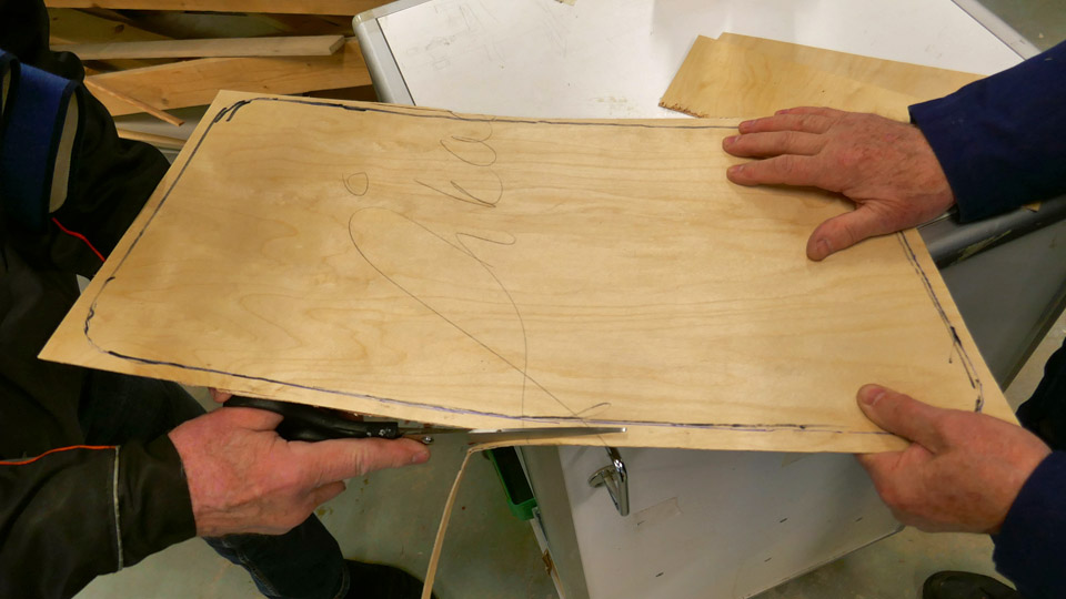
So the undersized windscreen plexiglass panes were detached and the chutes of both windscreens were cleaned of rust and dirt with a brush disc, attached to a battery driven drilling machine. To acquire new plexiglass panes, a window shaped template was made of 1,2 mm plywood. This template was cut so, that the template of the windscreen pane could just be slid into the chute of the frame through the windscreen opening.
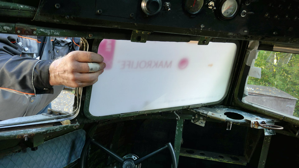
The plan is to glue the new plexiglass pane to the chute with silicone. In the process of gluing the plexiglass pane will be supported so that it leans with each edge a few mm against the inner side of the frame chute. Thus the plexiglass pane would cover the whole windscreen opening and the silicone seam would become watertight.
WE had ETRA cut us two windscreen panes according to the plywood templates, from 5 mm thick UV-protected polycarbonate plexiglass. When we fitted them into the DO-5 windscreen chutes, after a bit of filing, we got the panes to click into place inside the windscreen frame.
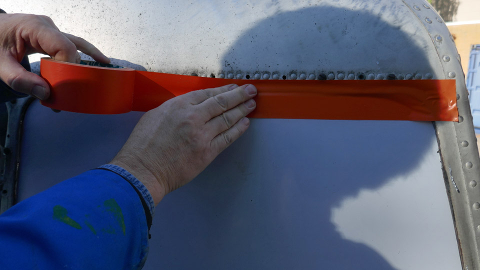
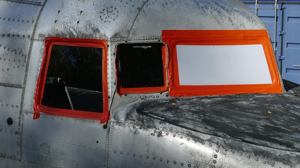
Because the autumn temperatures had sunk to about 10 degrees centigrade, we decided to postpone the gluing of the plexiglass panes to warmer weather next spring. Instead, we taped the new plexiglass panes, covered with protective plastic, on the outside of the aircraft with orange tape to the frames of the windscreens in order to stop rainwater or snow from getting into the cockpit. The tape covered completely the seam between the fuselage and the frame of the windscreen. We covered the seams of the cockpit’s side widows in the same manner, to prevent rain from penetrating into the cockpit through them.
Another preparation for winter was to cover the tail section with a protective tarpaulin. The vertical and horizontal stabilizers have been dismantled. Thus rain and snow have free access into the fuselage through the openings. We got hold of a large tarpaulin, with which we covered the tail section completely. Photos: Lassi Karivalo Translation: Matti Liuskallio. |
|
Avainsanat: aviation history, restoration, Tuesday Club, DO-5;DC-3, C-47, Dakota |

Ilmailumuseot.fi - Aviationmuseums.fi