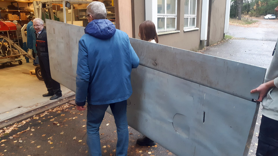
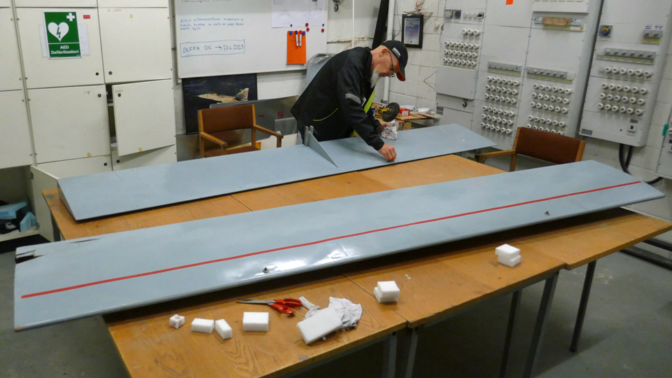
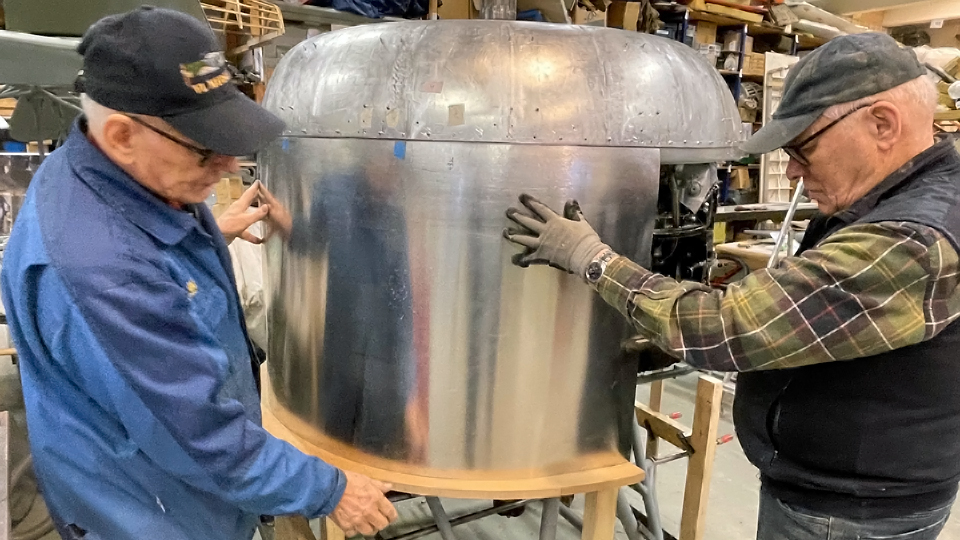
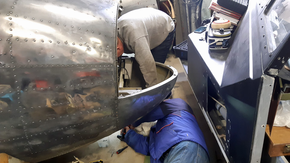
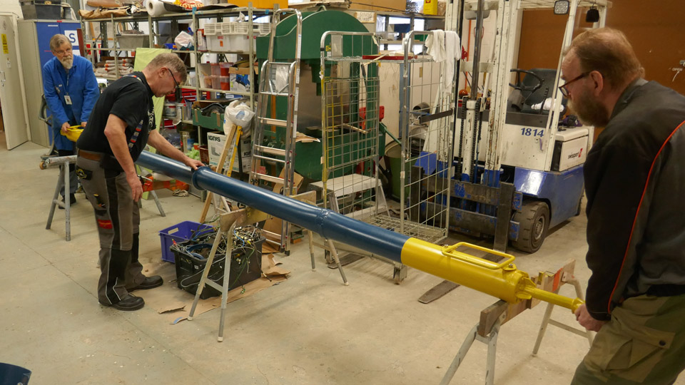
The restoration of OH-XEA Ressu has been startedTiistai 21.11.2023 - Tuesday Club member As told in the previous blog, the parts of the OH-XEA, designed and built in the 1960s by the Hietanen brothers from Turku, will be restored by the Tuesday Club. The aircraft was nicknamed Ressu. Its wings, horizontal stabilizer, elevator, rudder, tail wheel assembly, wing struts and fuel tank have been brought to the Finnish Aviation Museum. We will concentrate on the restoration of its fuselage frame later. When the condition assessment and the restoration plan of the Ressu’s parts brought to the Museum had been completed, it was time to set to work.
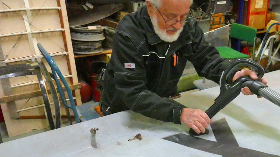
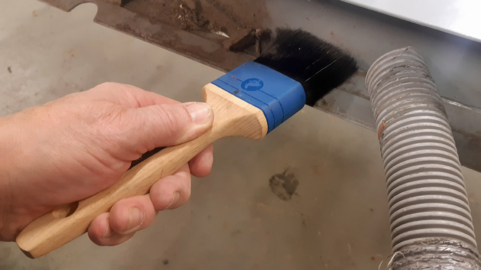
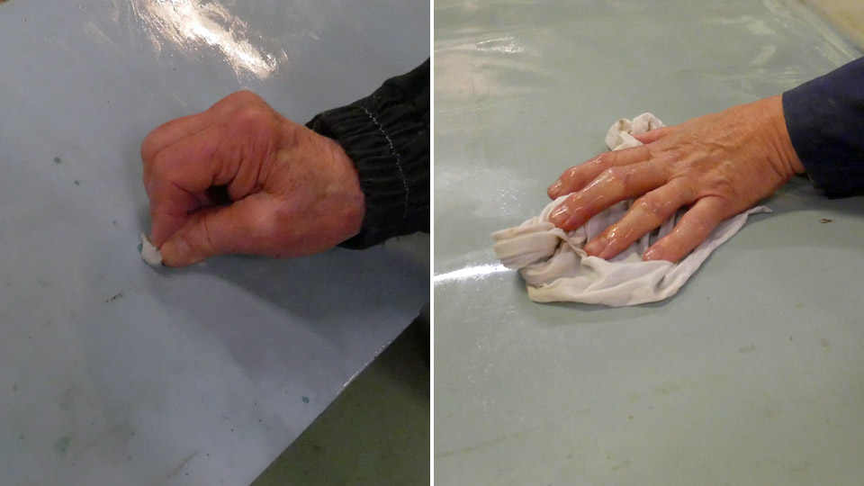
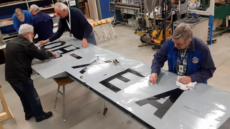
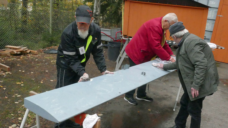
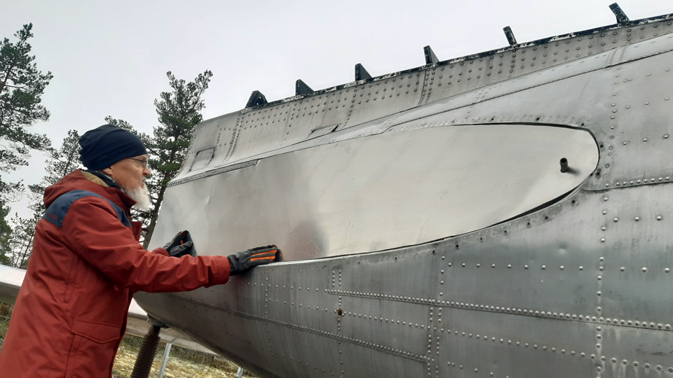
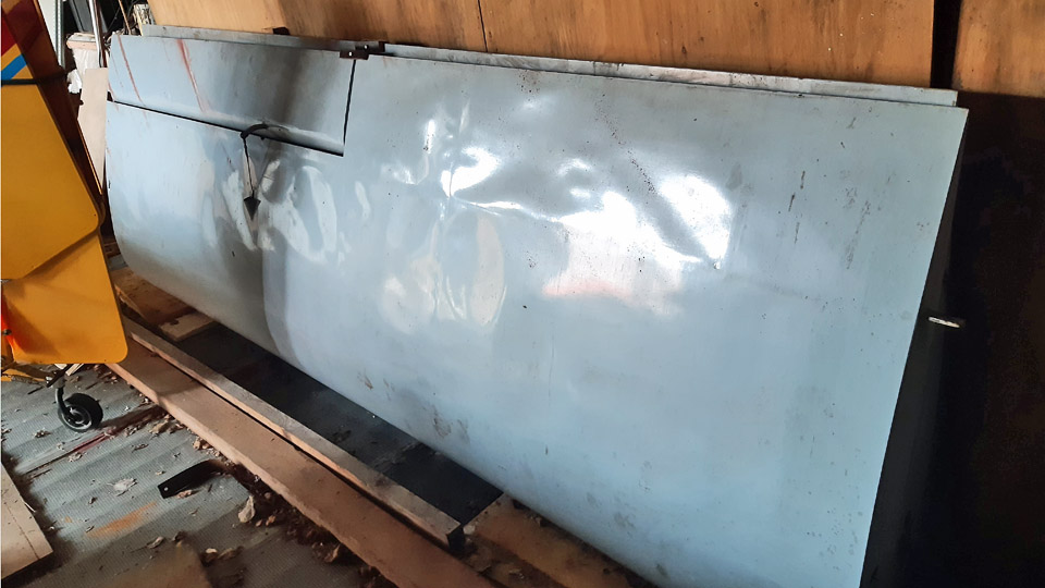
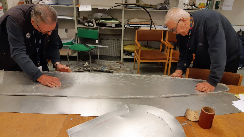
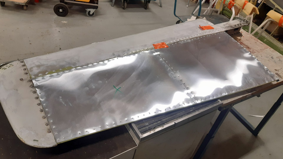
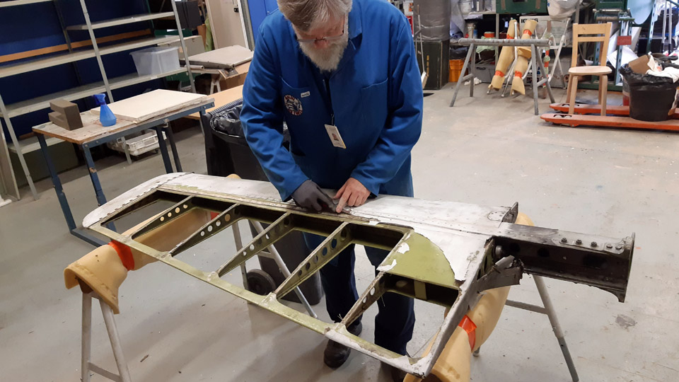
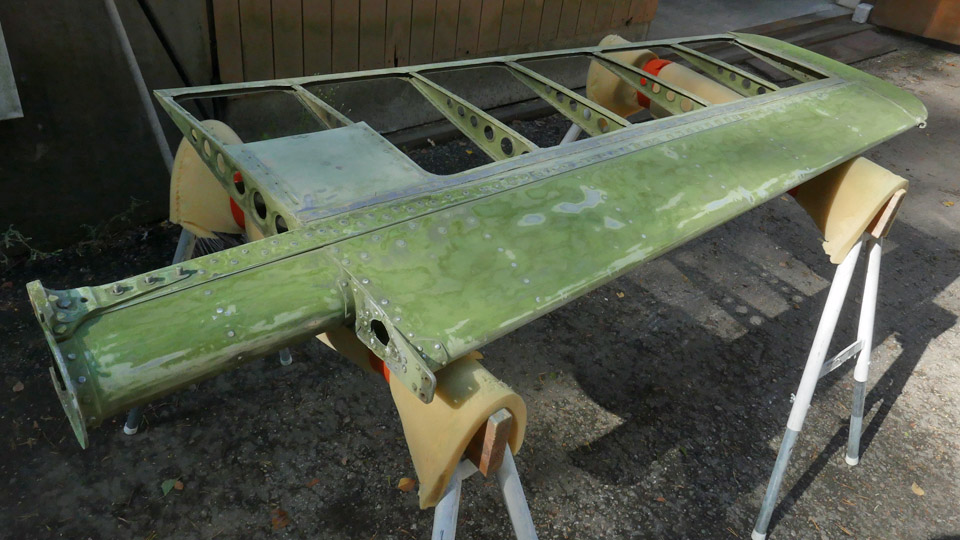
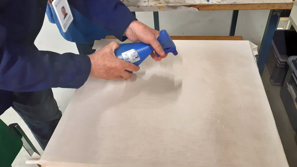
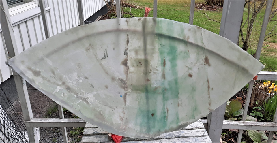
The restoration of the wings was started by cleaning the plywood surfaces, painted blue. Both wings were brought to the restoration workshop of the Finnish Aviation Museum. We started the cleaning of the painted wing surfaces with a well-tried method: a magic sponge. Naturally the worst dust was first vacuumed off. The aileron was unfastened to be washed separately. The dust in the joint of the aileron and the wing was brushed off with a paint brush and vacuumed clean.
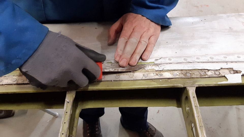
When using a magic sponge no cleaning agent is used. The tools you need are the magic sponge, a soft cloth, and half a bucket of water. The painted surface of the wing is cleaned by rubbing the surface of the wing, a small area at a time, with the magic sponge dipped in water and squeezed damp. With the soft cloth in the other hand the rubbed area is wiped at short intervals. The magic sponge removes the dirt from the wing surface, and it is wiped off with the cloth, which is rinsed in the bucket. There were also splashes of red paint on Ressu’s wings. Even they could be removed with the magic sponge. The rubbing with the magic sponge does not damage the painted surface unless excessive force is used.
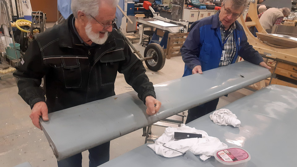
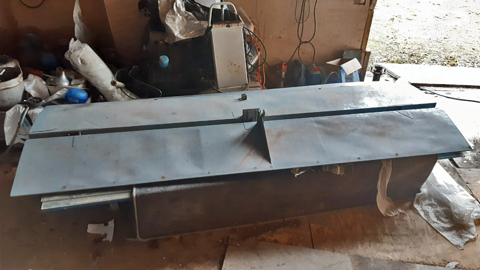
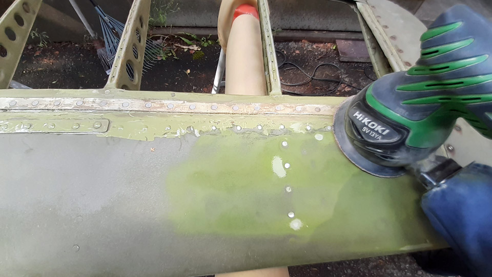
The plywood covered horizontal stabilizer and elevator were treated in a similar manner. We managed to get their surfaces very clean too. We were satisfied to see that after the wash the greyish blue surfaces of the wings, horizontal stabilizer and elevator were as if newly painted. We wonder whether they have been painted in the 1960s using durable Miranol enamel paint as the painted surface has been so well preserved.
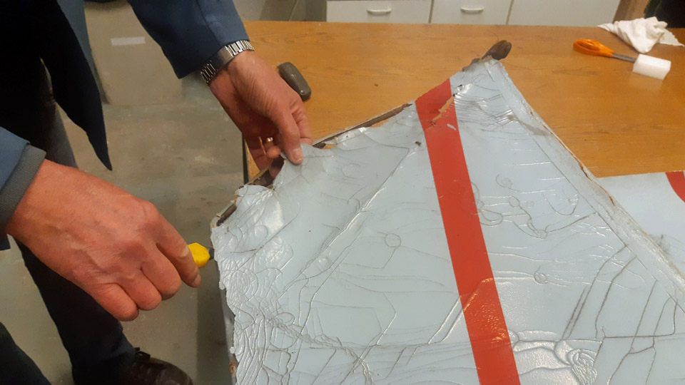
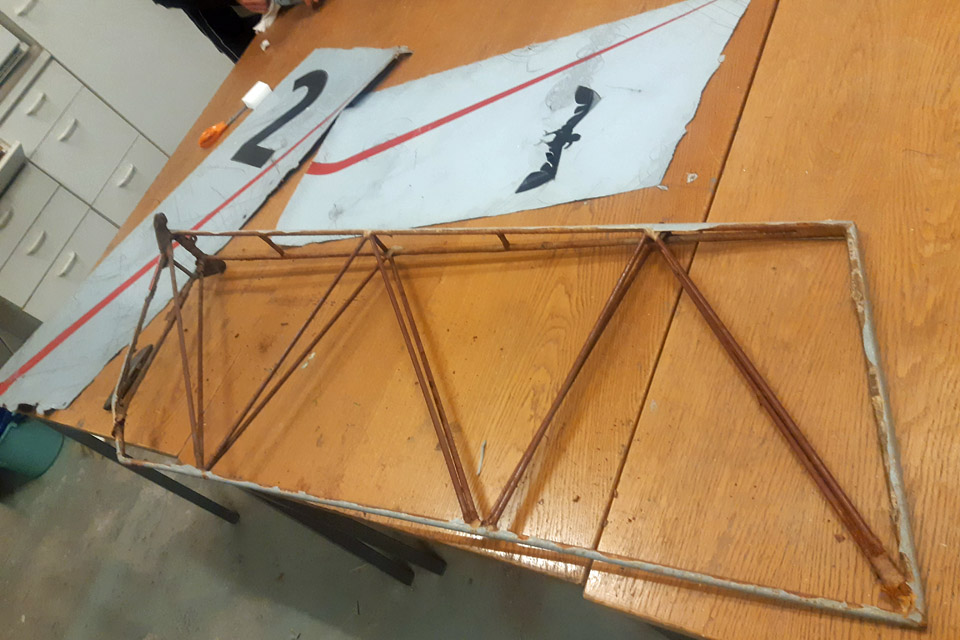
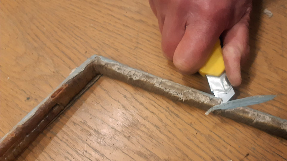
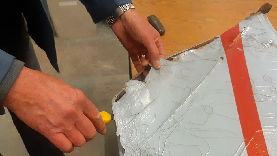
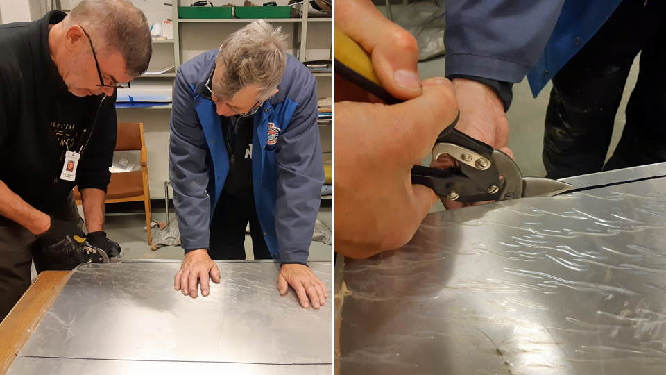
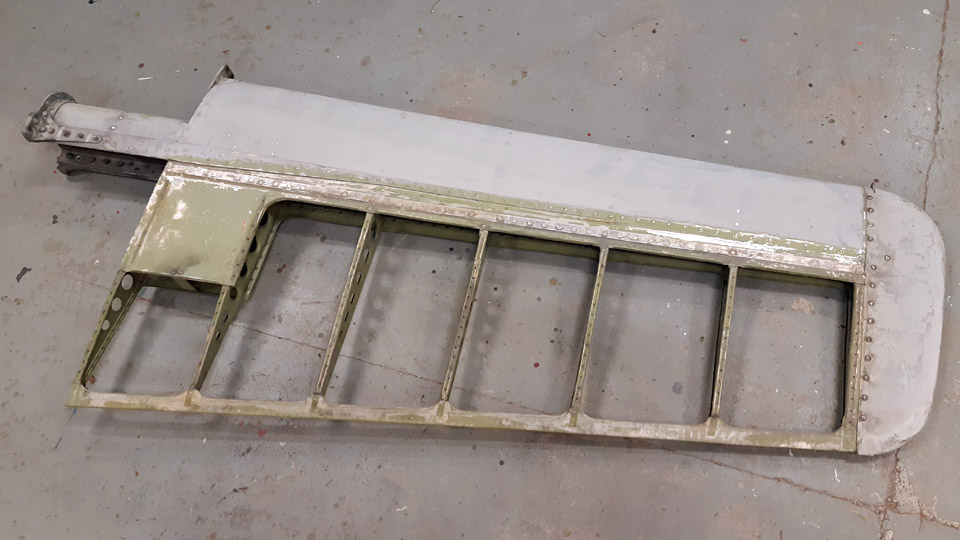
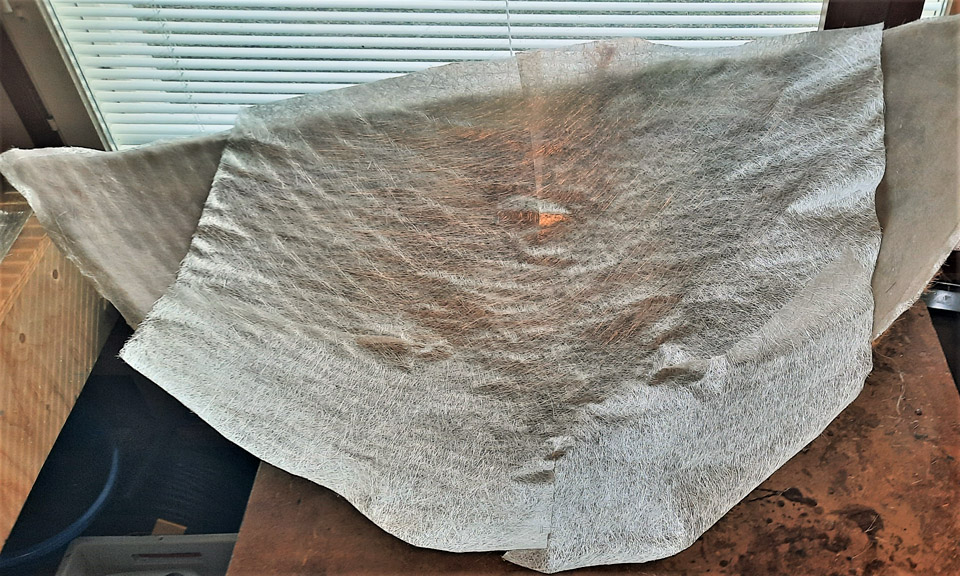
For the rudder surfaces no washing was needed, but the covering fabric was removed from the metal frame of the rudder. The covering fabric needs to be completely replaced. A carpet knife was used when removing the fabric. We could see that a strip of fabric had been spun around the outer edges of the frame. This strip protects the fabric which covers the metal rudder frame. On the other hand the covering fabric can be sewn on the fabric strip, but we could not tell whether this had been the case here. The fabric strip covering the edges of the metal frame was removed with a carpet knife. The rudder’s metal frame, stripped of the covering fabric, is now ready for rust removal and the surface treatment after it.
Photos by Reino Aatsalo.
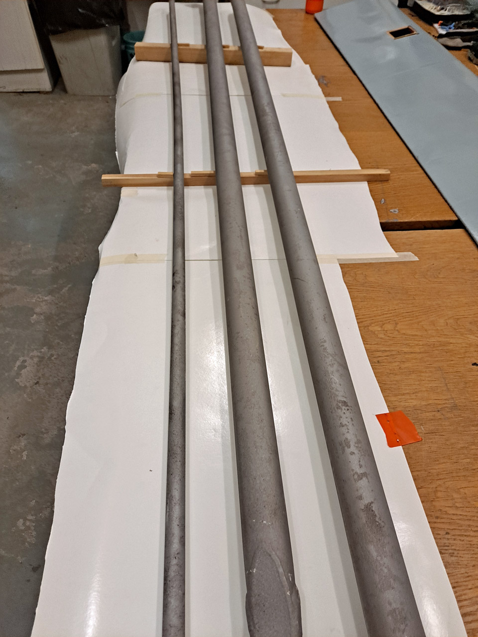
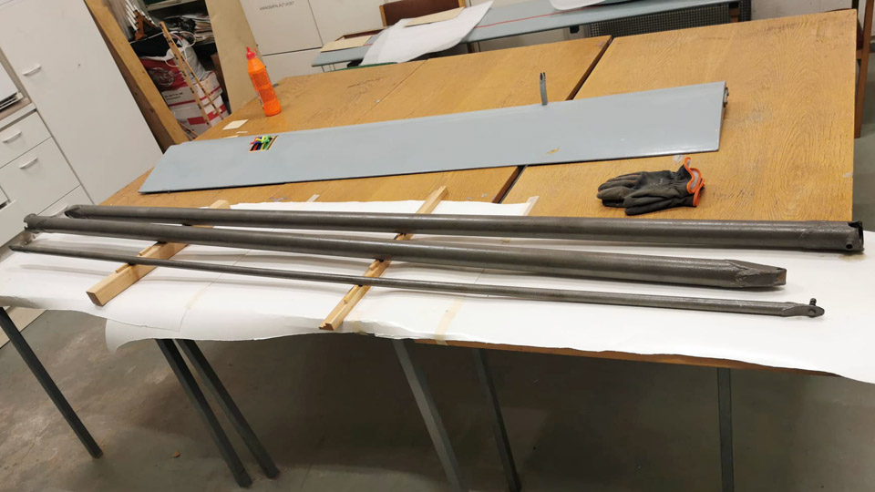
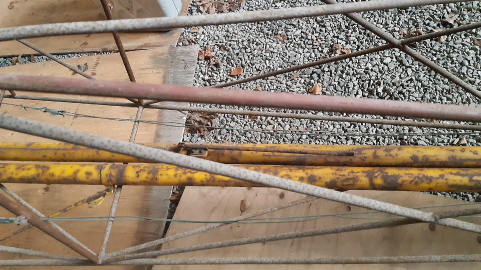
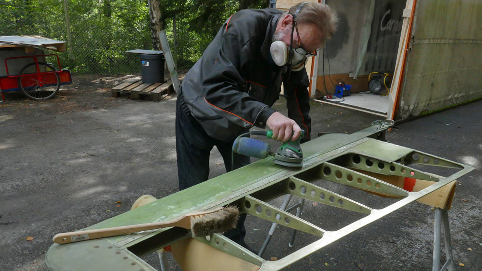
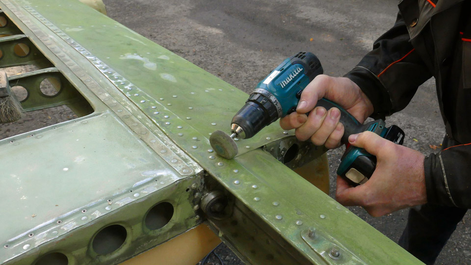
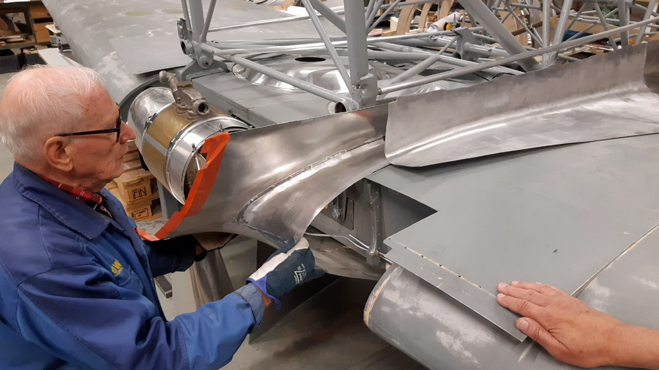
Photo by Antti Hietala. Three of the Ressu’s four wing struts have been preserved. The struts are surprisingly heavy, so they are probably made of ordinary steel tube. The surfaces of the struts have been painted yellow but are now covered in rust. The surfaces were sandblasted clean. Then the struts were treated with Isotrol varnish which prevents rust. Now the wing struts are waiting for their final surface treatment, and they will be painted yellow as in the original paint scheme.
Photo by Lassi Karivalo.
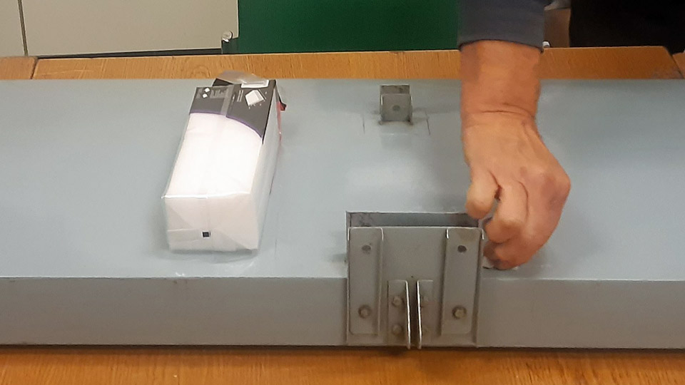
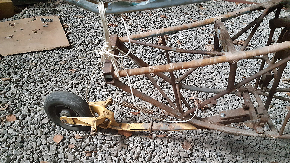
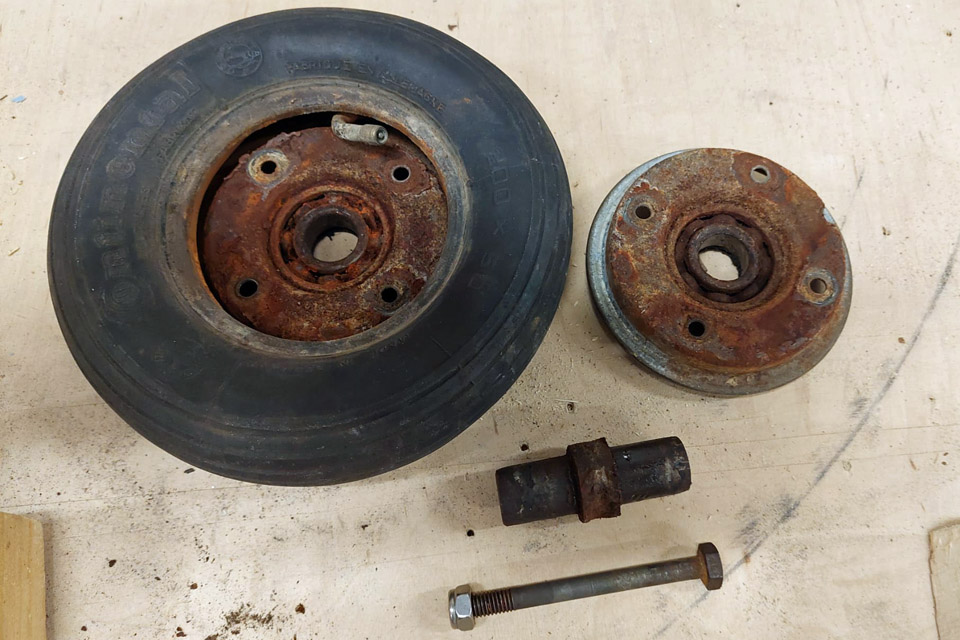
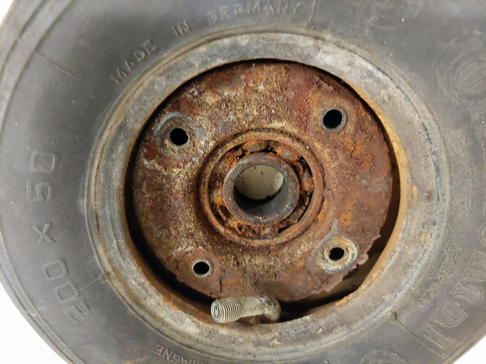
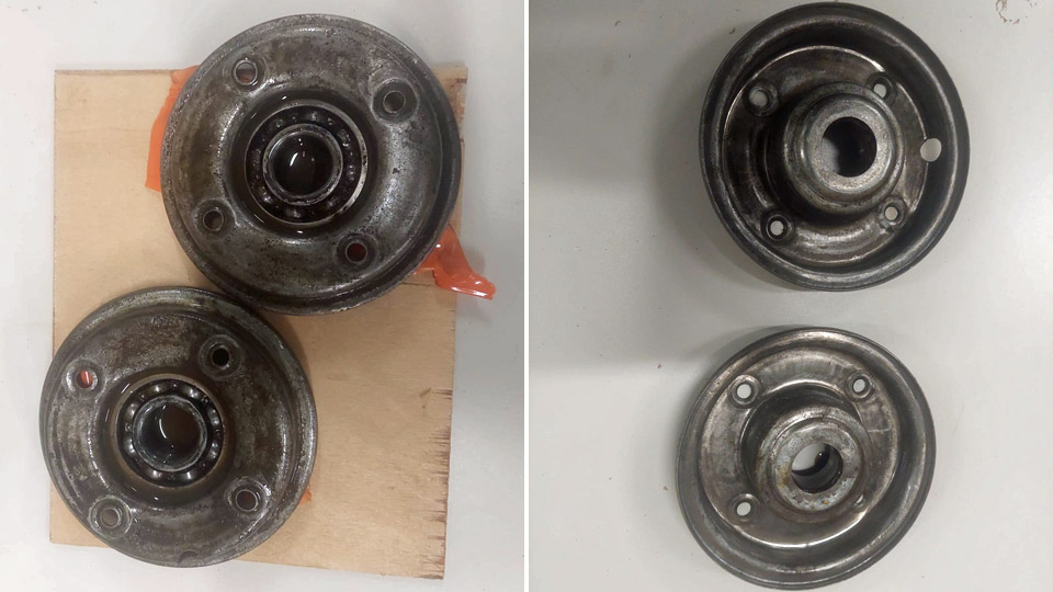
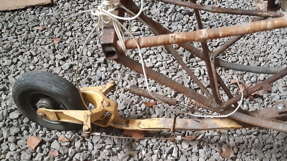
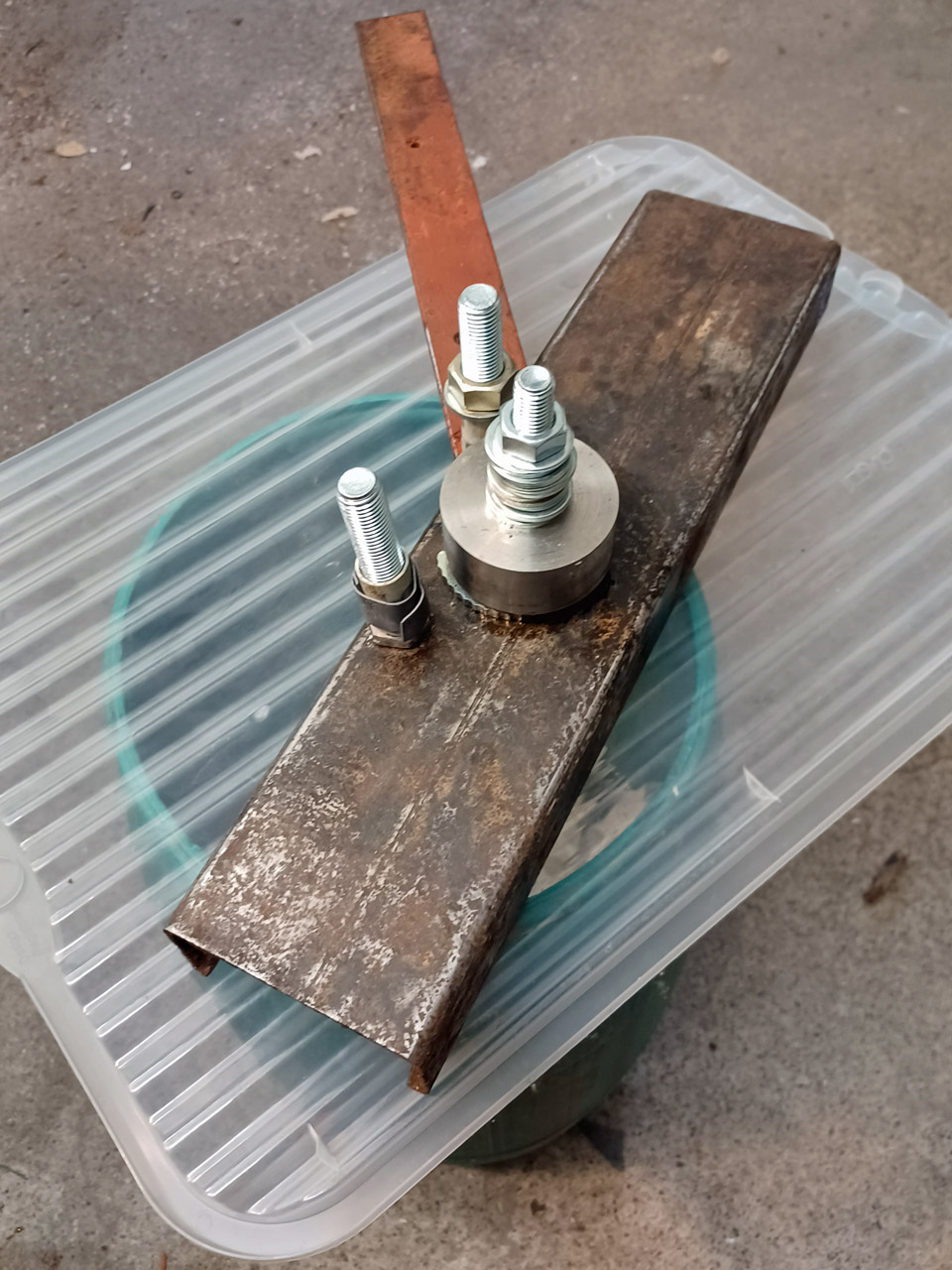
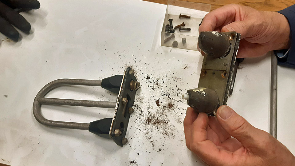
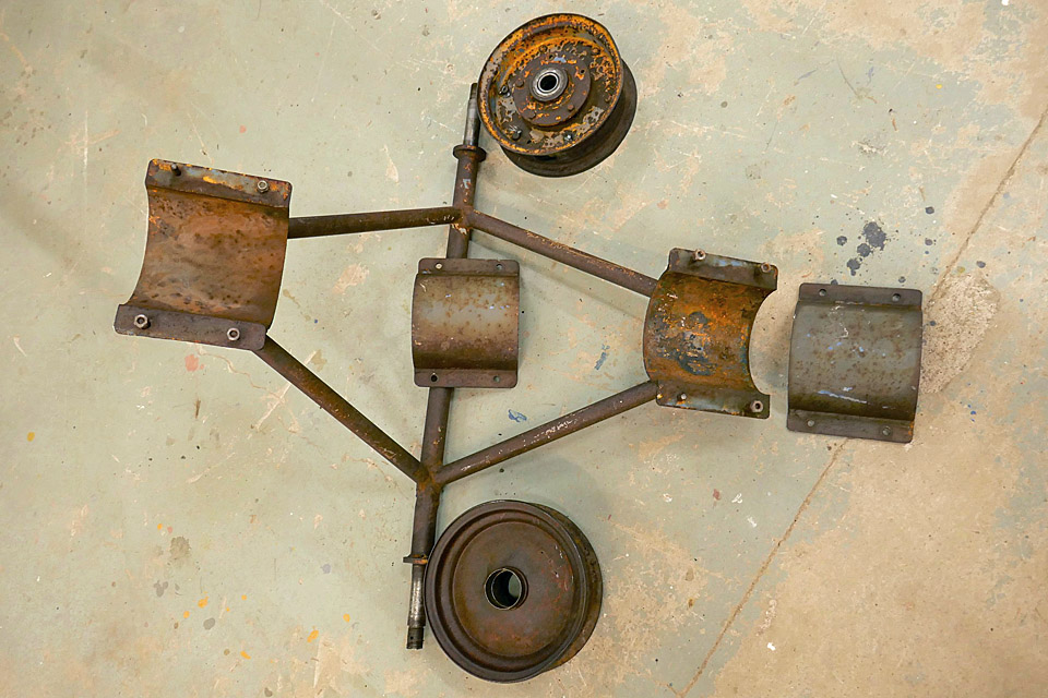
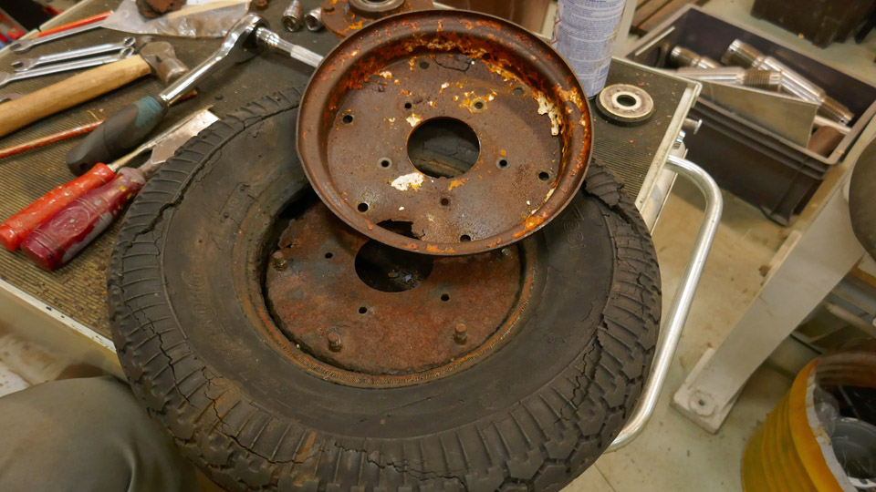
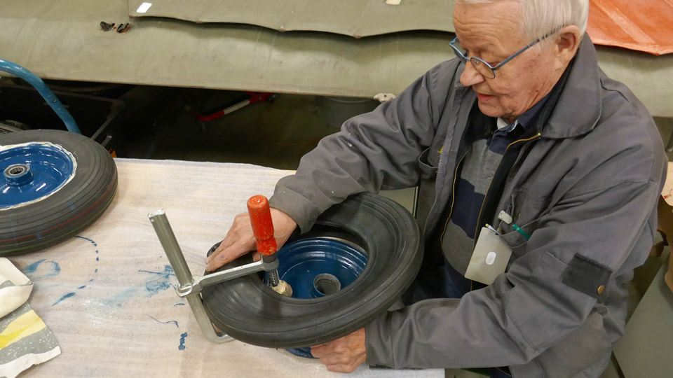
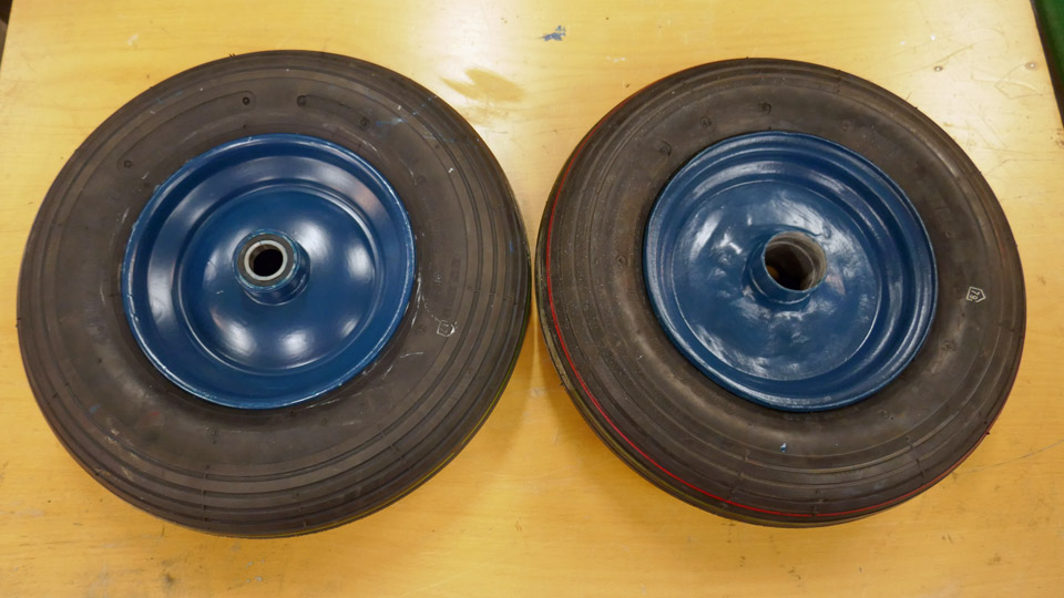
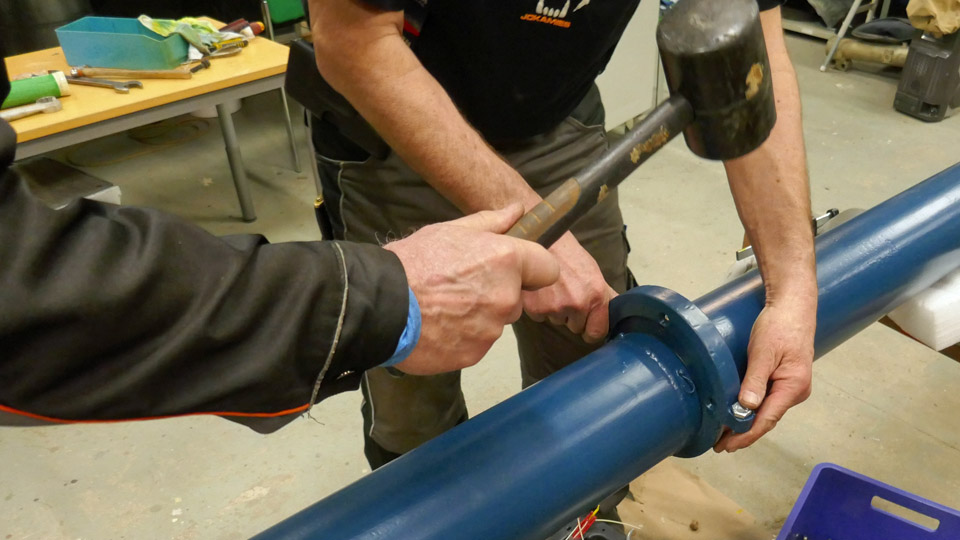
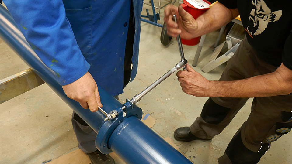
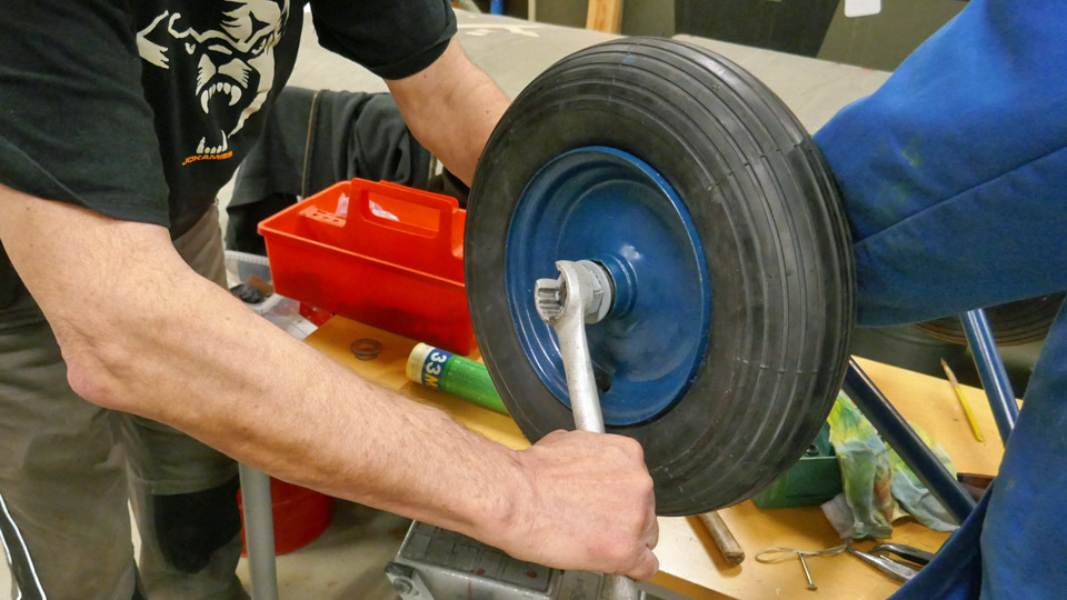
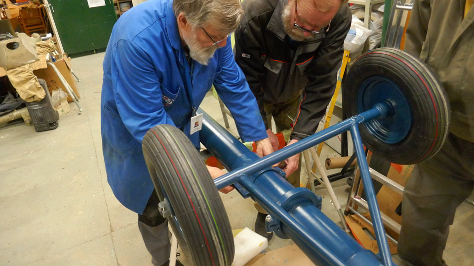
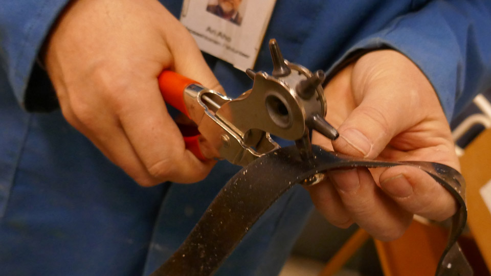
Photos by Osmo Väisänen. The restoration of Ressu’s sprung tail wheel assembly was started by disassembling it. Even the tail wheel had to be disassembled so that we will have access to the wheel bearings, which are totally jammed. When the four bolts on the wheel rim had been unfastened, the rusty wheel halves could be wrenched apart by force. When the bearings were visible, we sprayed a lot of rust removing chemical in them and on the rusted surfaces of the wheel rim and left them “to mature” for a week. When a week had passed, we were able to clean the wheel rim halves quite well from rust and the bearings were preliminarily working. The following task will be to repair the sprung tail assembly. Photos by Lassi Karivalo except if otherwise mentioned. Translation by Erja Reinikainen. |
|
Avainsanat: aviation history, restoration, Tuesday Club, Hietanen HEA-23b, OH-XEA, "Ressu" |
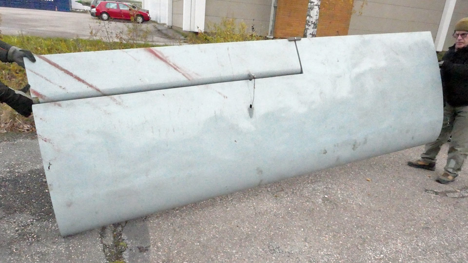
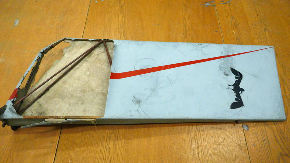
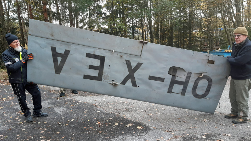
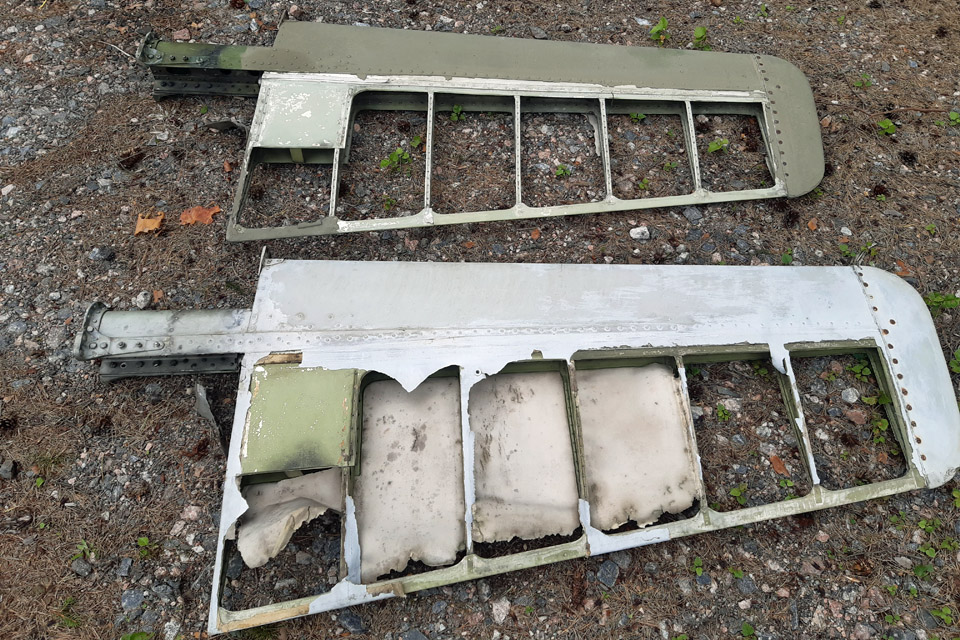
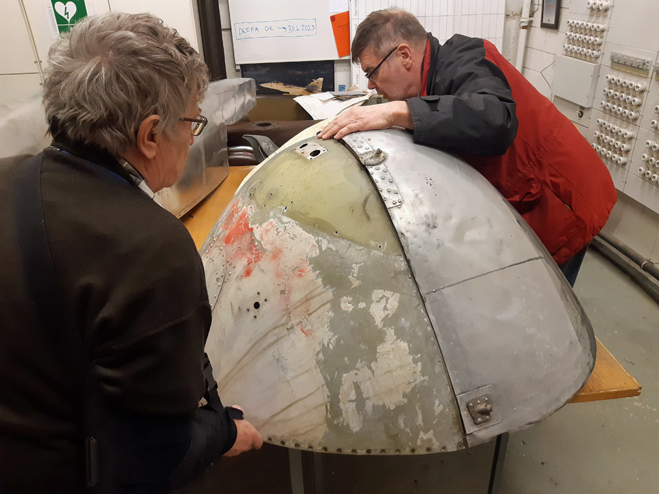
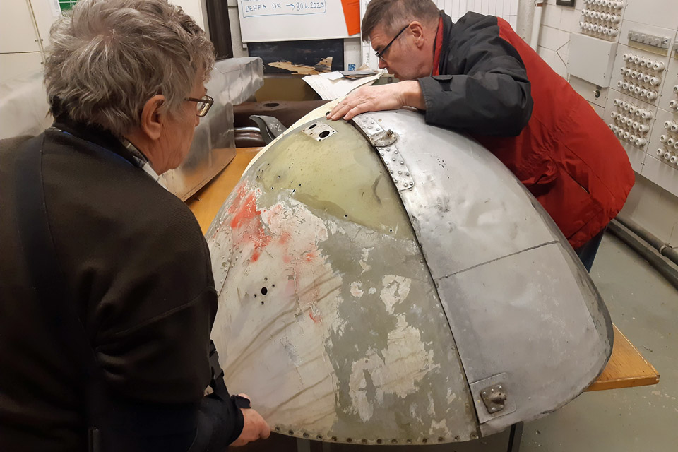
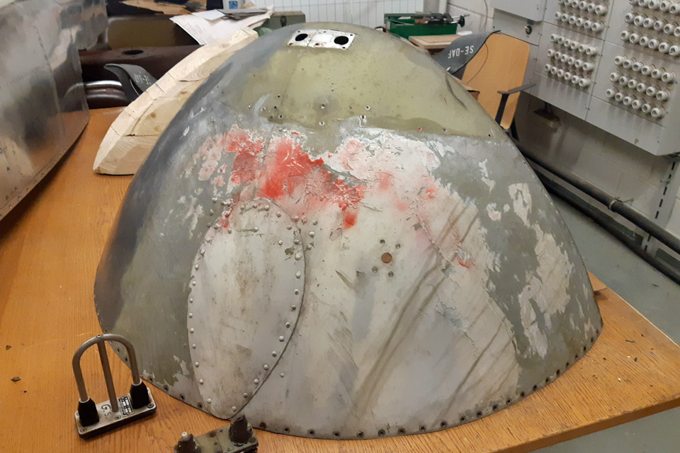
The condition and damage assessment of Hietanen OH-XEA Ressu and its restoration planSunnuntai 19.11.2023 - Tuesday Club member The Tuesday Club is starting the restoration of the Hietanen OH-XEA Ressu aircraft which has been stored at Lemu in the Turku area. The aircraft was built in the 1960s by Ari and Esko Hietanen from Turku. The first phase of the restoration will include the wings, horizontal stabilizer, elevator, rudder, tail wheel assembly, wing struts and fuel tank, which have been brought to the Finnish Aviation Museum from Lemu. The fuselage has no covering, but it remained at Lemu, and its turn will come later. The first step in the renovation work is to assess the condition of the aircraft and its possible damage. Therefore we took the Ressu’s parts into the restoration workshop at the Finnish Aviation Museum and went carefully through the condition and damages of each part and made preliminary restoration plans for them.
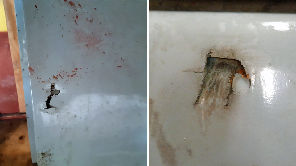
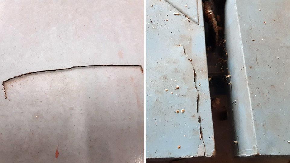
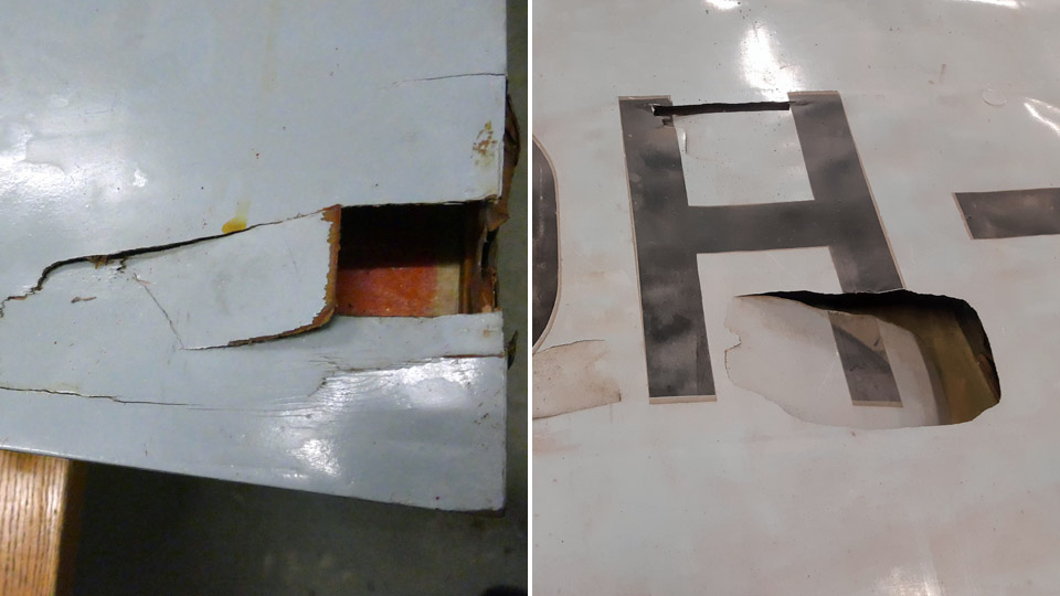
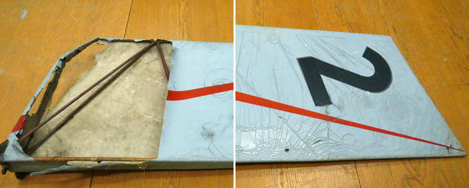
We could see that the plywood covered surfaces of the wings, horizontal stabilizer and elevator are very dirty and have stains of red paint. The damages on the plywood covering are mainly small crushes or holes. However, on the underside of the left wing there is a large area around the registration mark where the plywood covering is badly broken. Or should we say has been intentionally broken – it certainly looks that way. The first phase in the restoration will be to clean the surfaces of the wings, horizontal stabilizer, and elevator and then to repair the damages on the plywood covering.
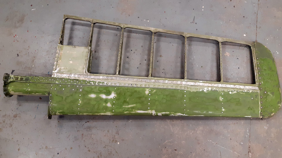
Ressu's rudder has metal structure and fabric covering, in similar manner as the tubular structure fuselage. The covering fabric is torn on one side of the rudder and a piece is missing.
The rusty metal frame of the rudder can be seen under the torn fabric. The metal frame will be cleaned and painted as it originally was. It seems that the frame has been painted with red Ferrex, the anti-rust paint which was commonly used in the 1960s. The red colour is visible under the rust. We will paint the frame using modern red Isotrol paint.
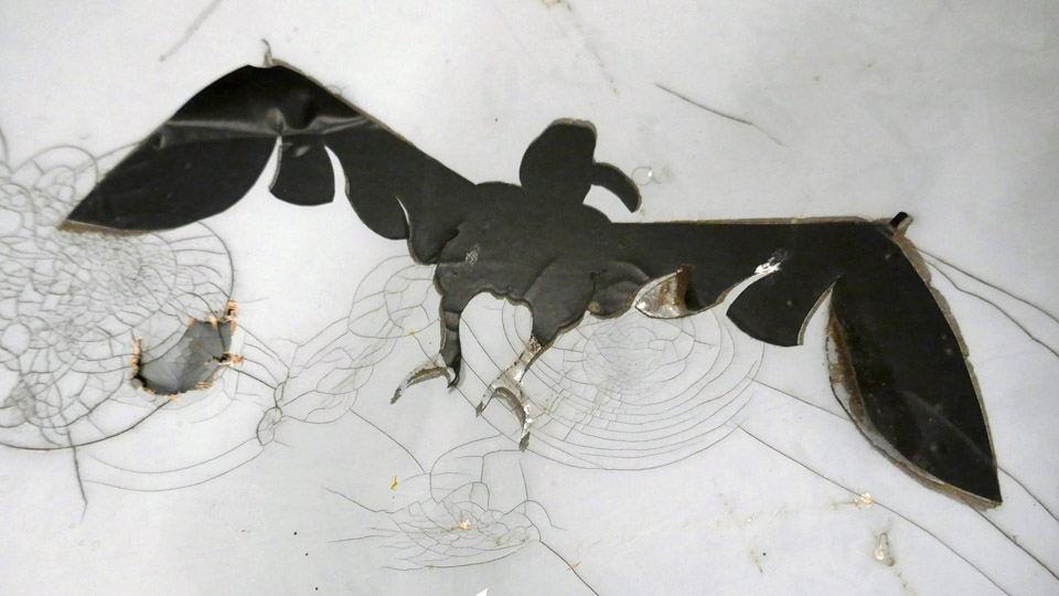
Finally the rudder will be covered with new fabric and painted pale blue, following the original paint scheme. Red stripes will be painted on both sides of the rudder, following the original look. Number 2 will be painted on the left side and a black bird figure on the right.
Ressu's tail assembly has metal structure and an air-filled tyre. The wheel bearings are completely stuck. We will try to repair the wheel into operating condition. The tail frame will be cleaned of rust and painted yellow, following the original paint scheme.
Ressu’s wings are supported with two wing struts, made of metal tube. Two of them are sturdier, fastened on the brackets on the wing’s front spar, and the two thinner ones are fastened on the brackets on the rear spar. We have both front struts but only one rear strut. The wing struts had been stored inside Ressu’s fuselage frame. The struts have been painted yellow but are now badly covered in rust. They will be sandblasted clean by a contractor and painted yellow as the original ones. We will make a new rear strut to replace the missing one.
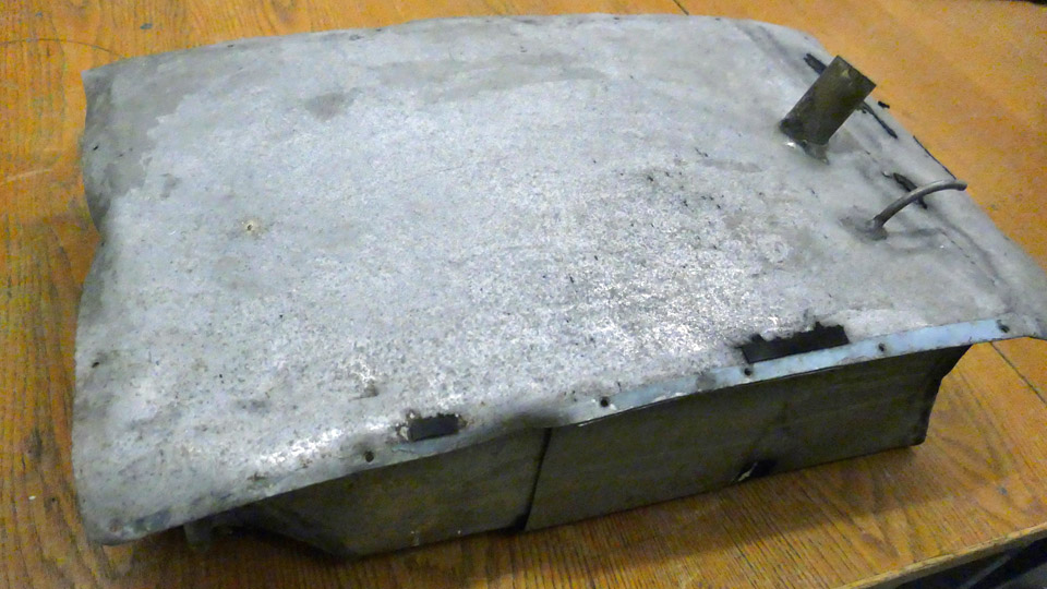
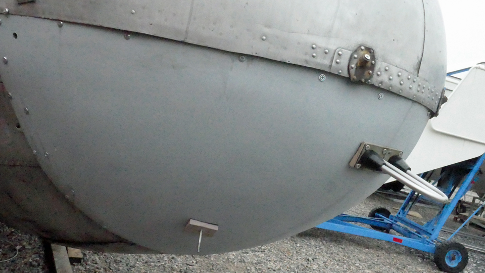
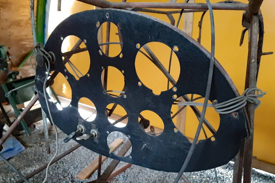
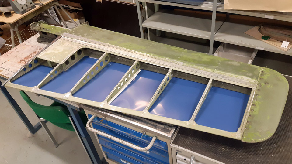
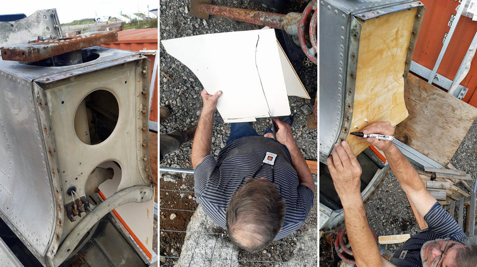
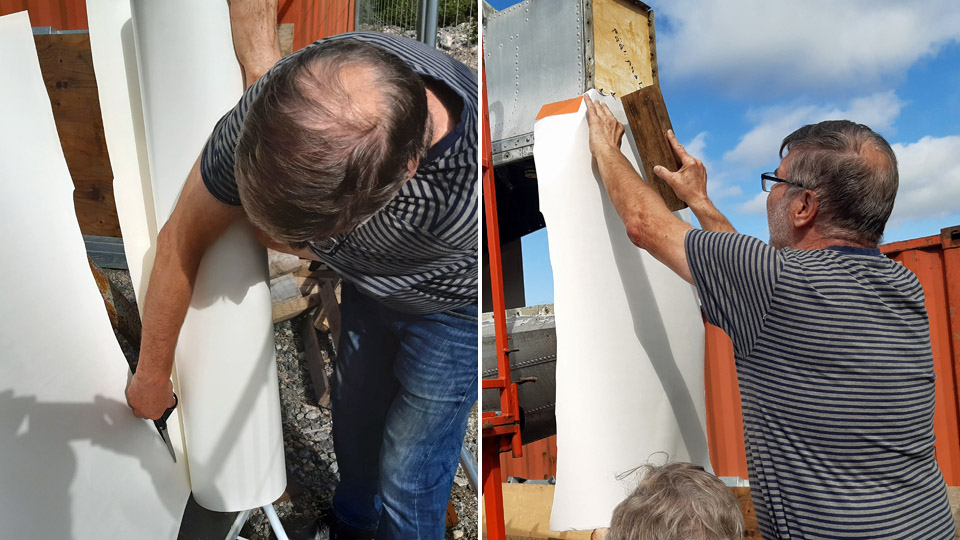
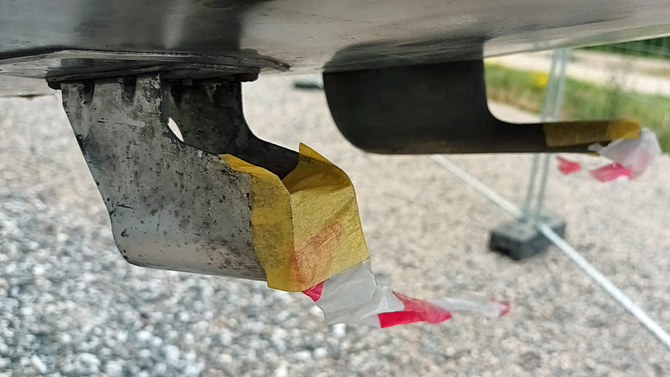
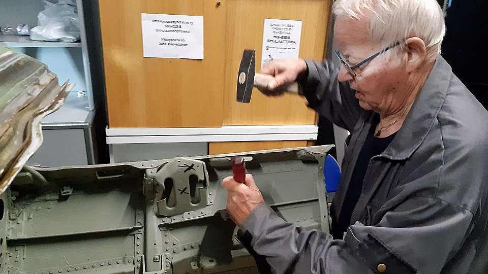
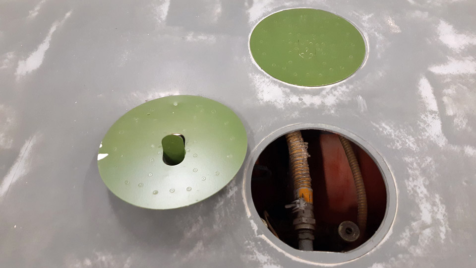
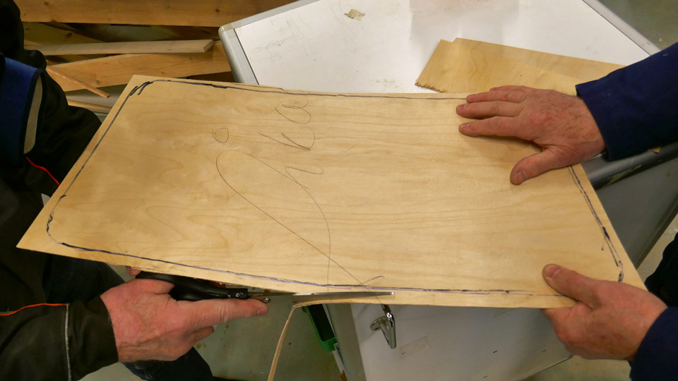
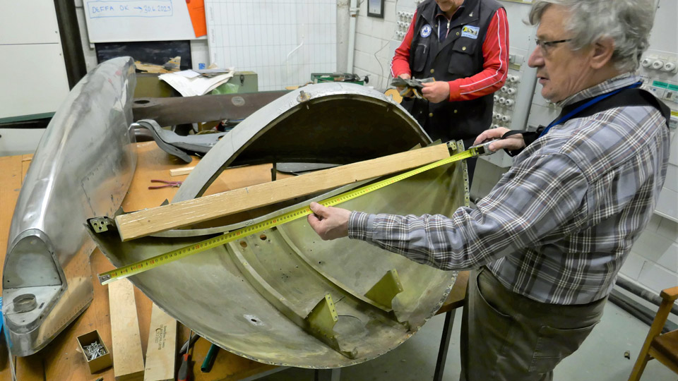
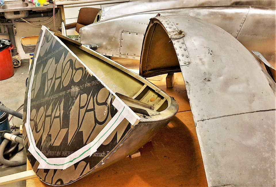
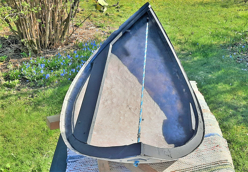
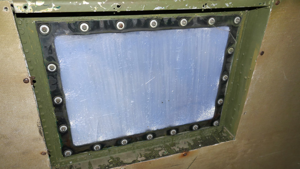
The fuel tank is located at the root of the left wing, it has been lowered into place from the upper side of the wing. The fuel tank has dents, and they will be straightened. The fuel tank has had some kind of cap with a rubber seal, there are marks of it left on the wing as well as on the tank. The cap has disappeared. If we can find out what the cap has been like, we will make one. And if we can’t find what it has been like, a good alternative is to make a cap from e.g. 1,2 mm thick aircraft plywood. The Hietanen brothers have obviously been planning to double the size of the 21-litre fuel tank. We can judge this from the fact that the wing rib next to the tank had already been removed and the wing’s plywood covering had been opened between the wing spars up to the following rib. We will, however, restore the wing structure to its original condition where there is only space between the wing root rib and the first rib for the original fuel tank. This means that the missing rib will have to be made and the opened plywood covering repaired. Photos by Lassi Karivalo. Translation by Erja Reinikainen. |
|
Avainsanat: aviation history, restoration, Tuesday Club, Hietanen HEA-23b, OH-XEA, "Ressu" |
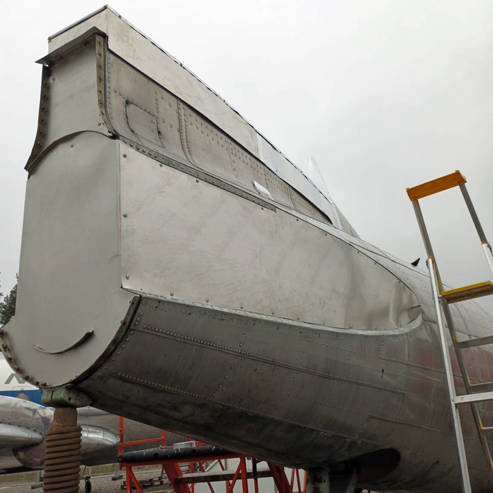
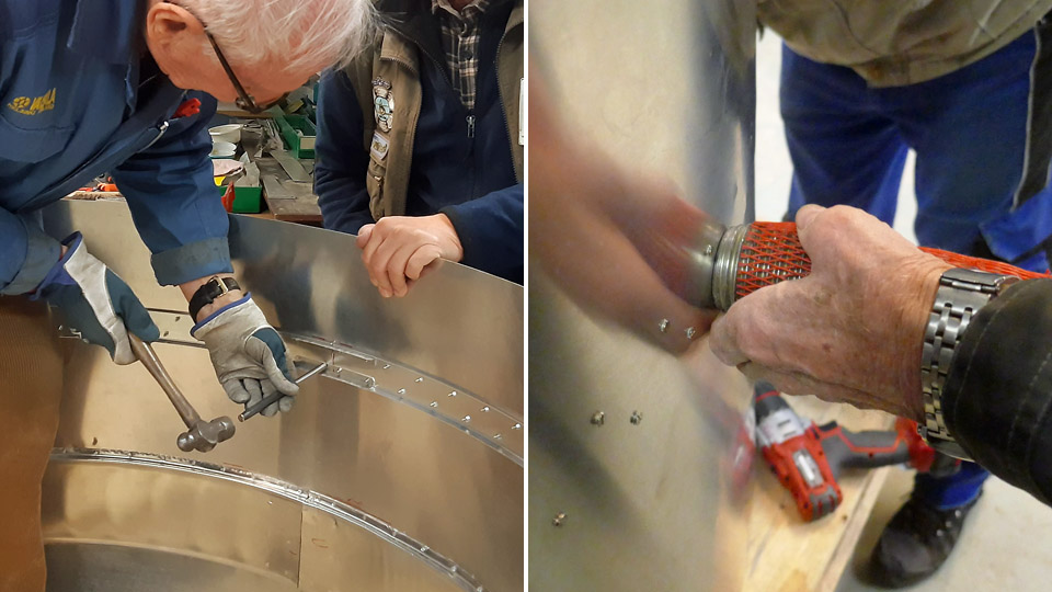
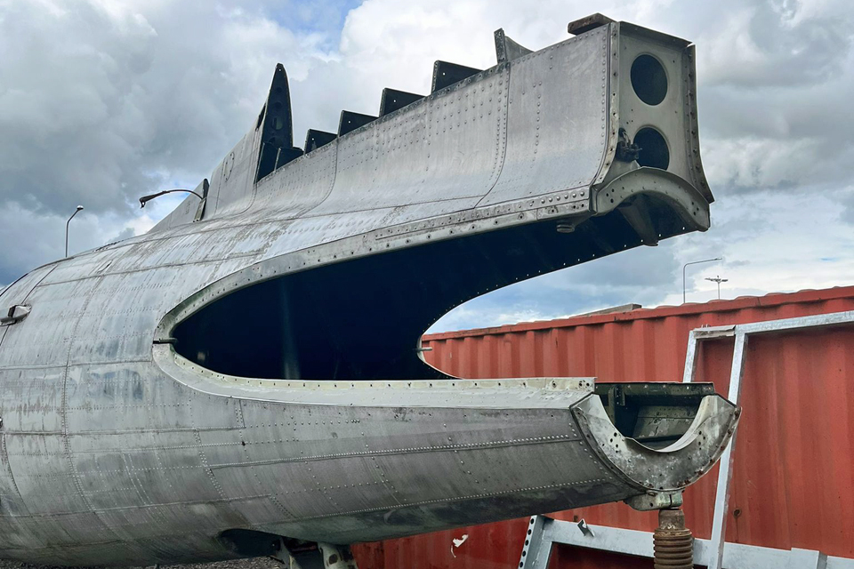
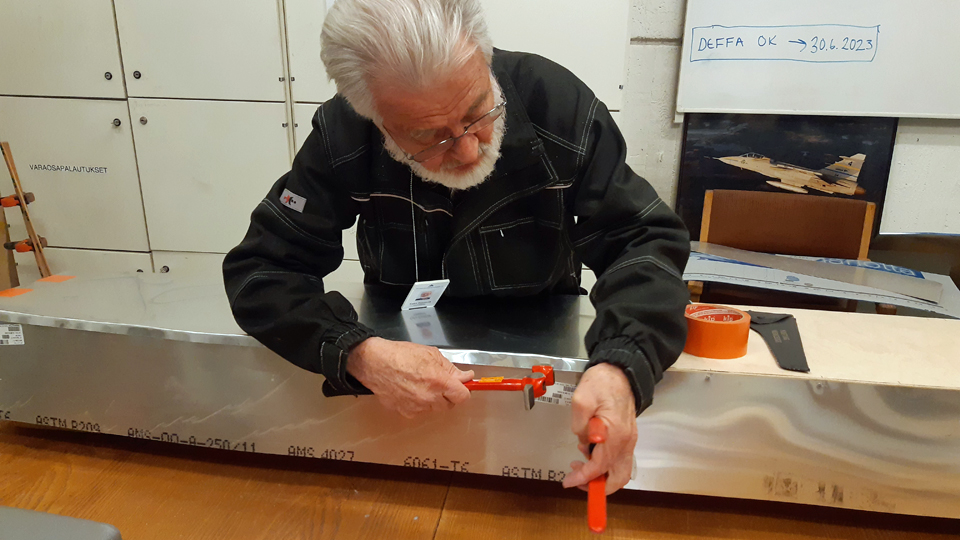
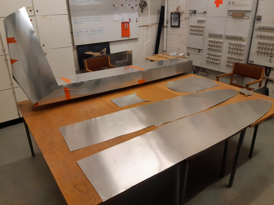
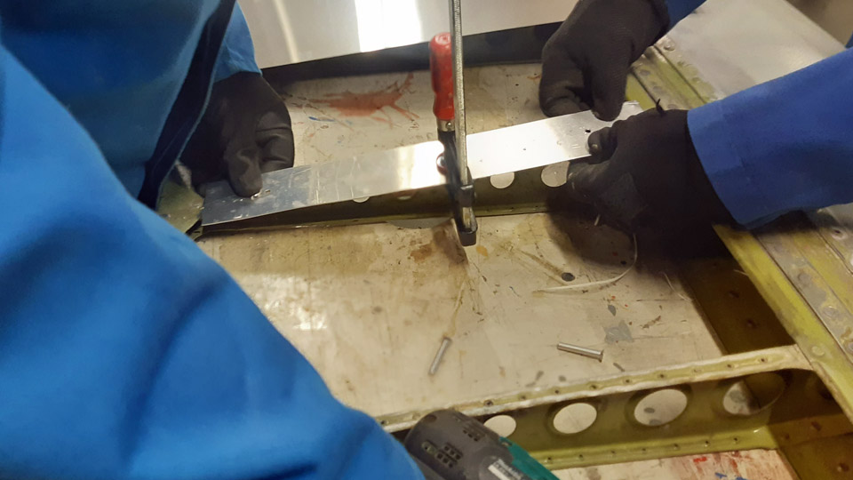
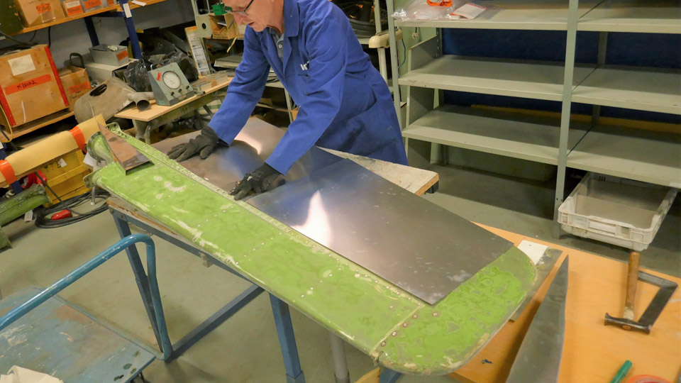
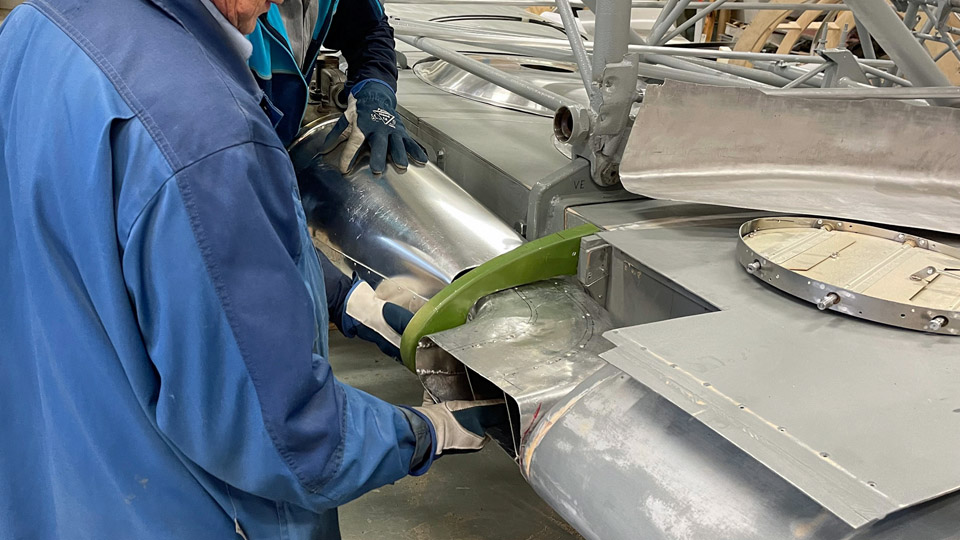
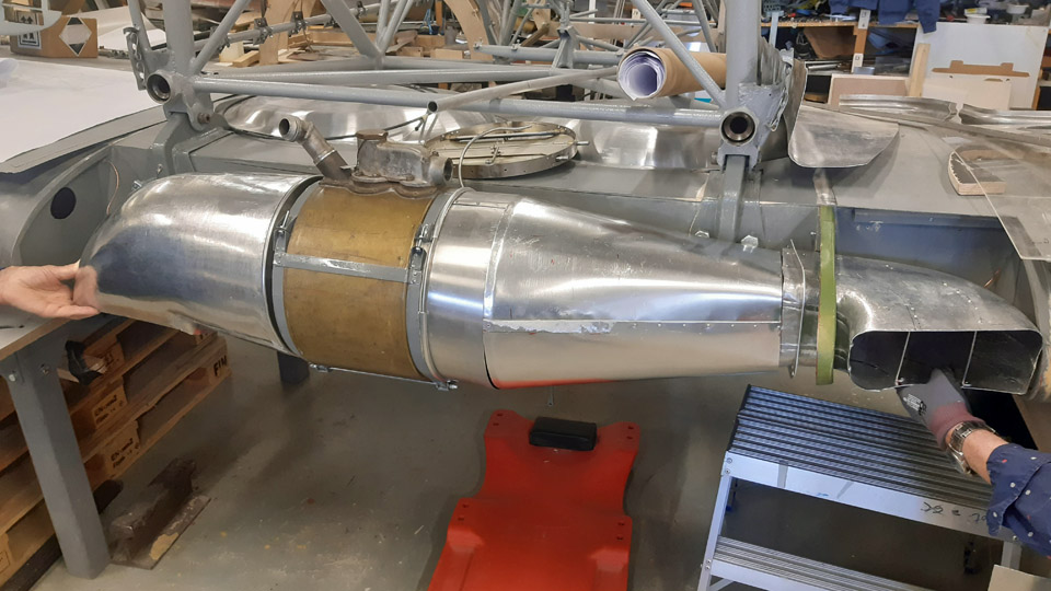
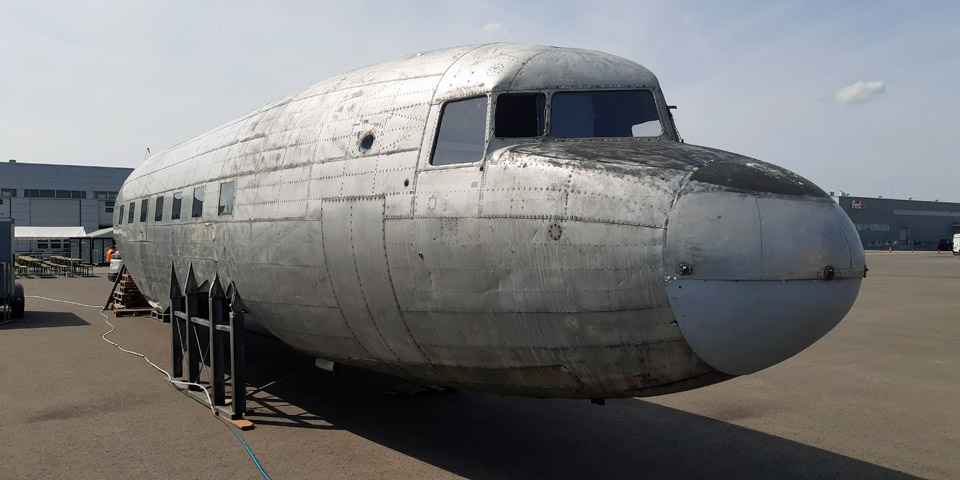
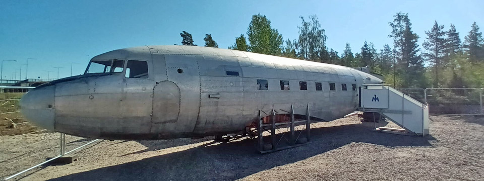
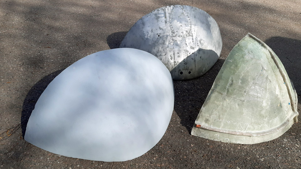
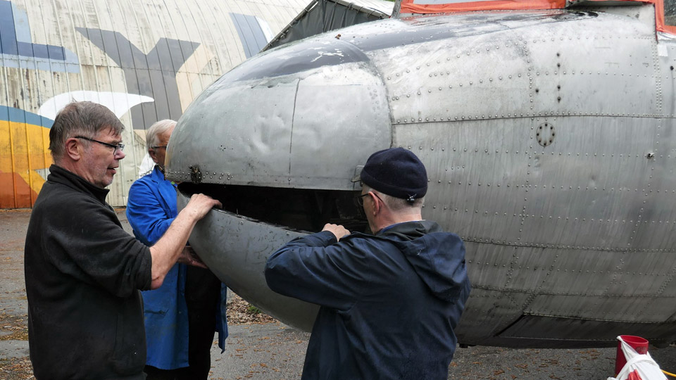
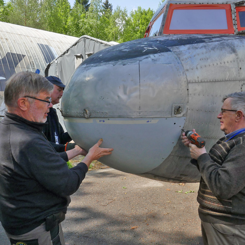
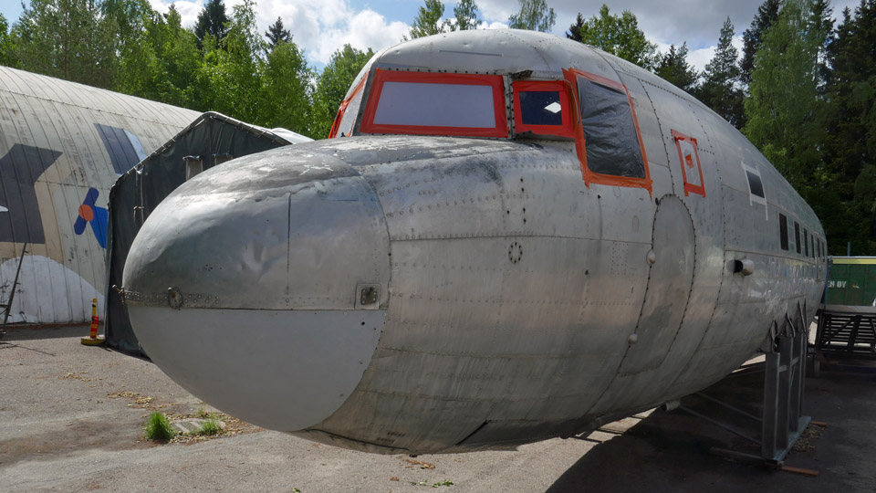
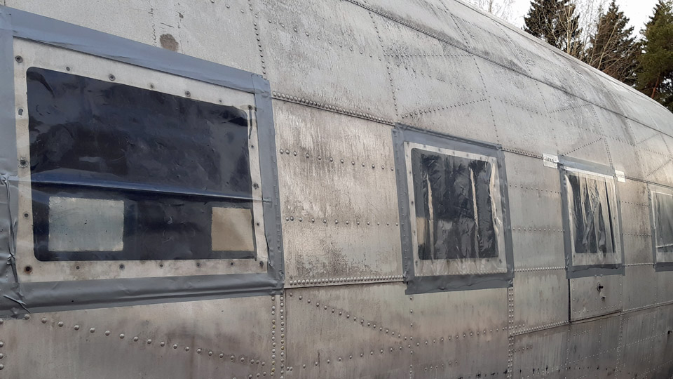
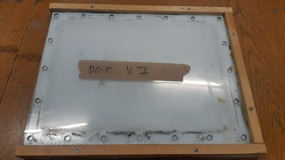
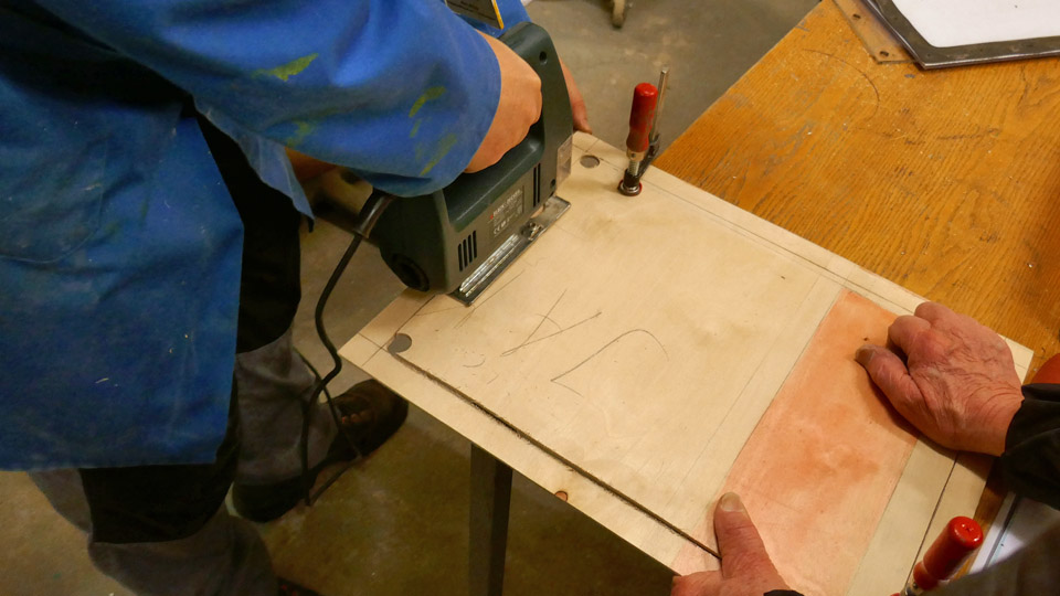
Covering the DO-5 tail openingsSunnuntai 12.11.2023 - Tuesday Club member The rain covers for Aviation Museum Society owned Douglas C-47 (DO-5) tail openings were finished in October. The tail has been without vertical and horizontal stabilizers and the tail cone for donkey’s years. Due to that rainwater and snow have penetrated into the fuselage. The building of the covers out of aluminium plate has been reported already earlier in a Tuesday Club blog.
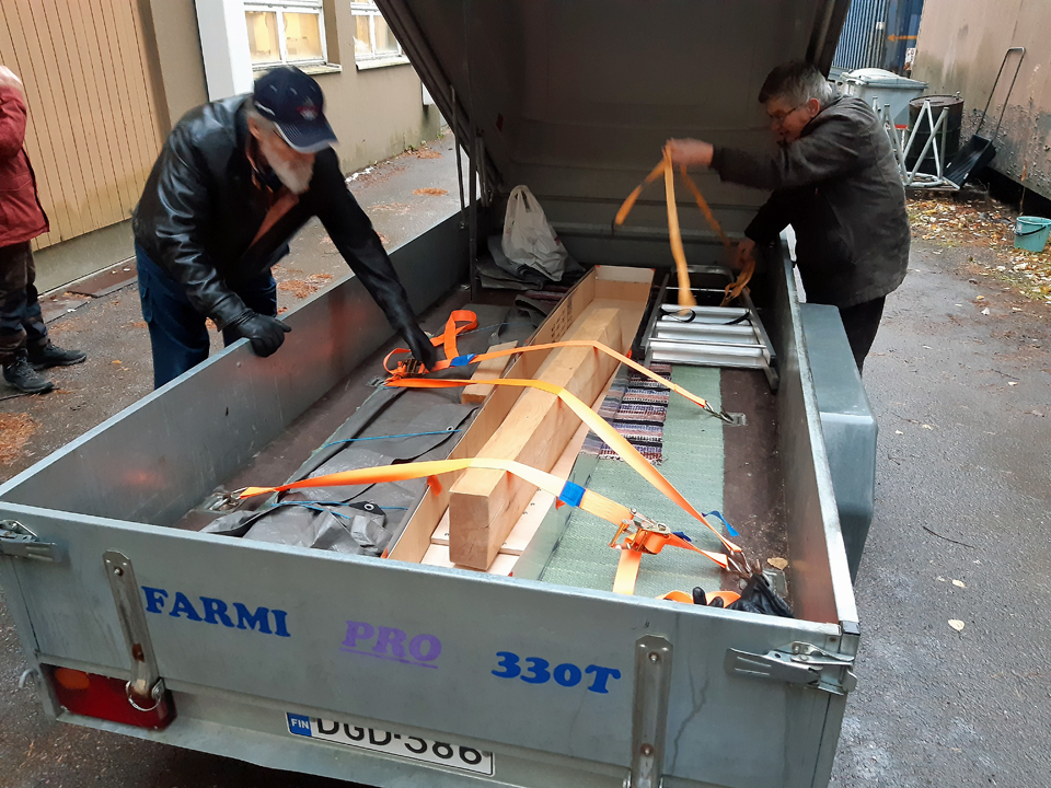
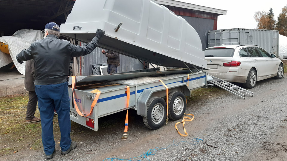
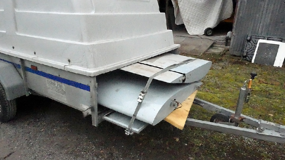
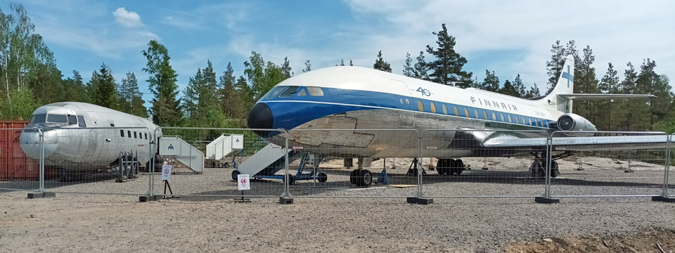
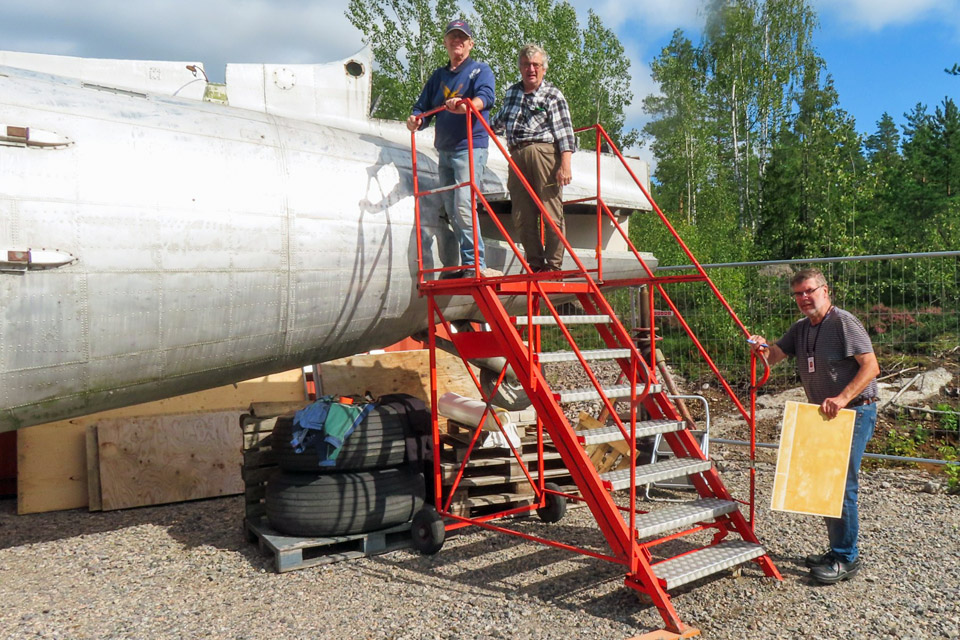
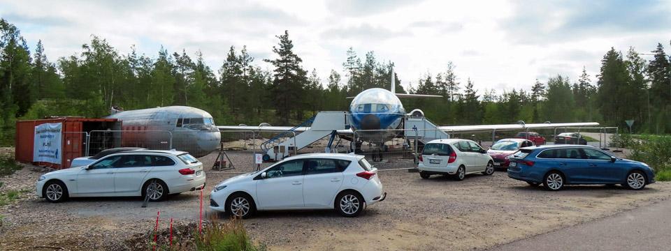
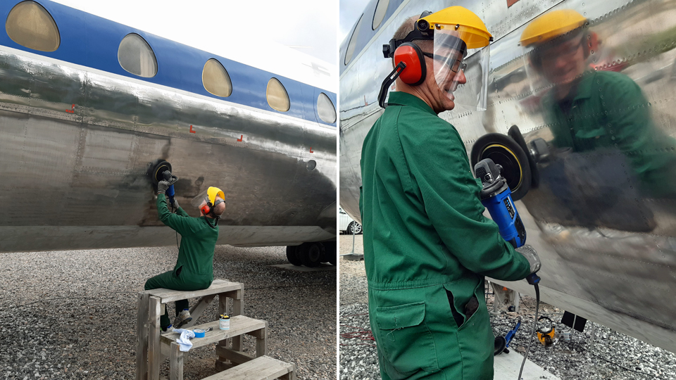
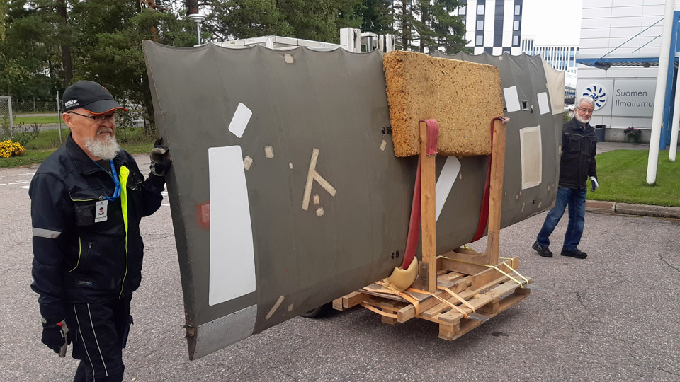
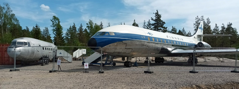
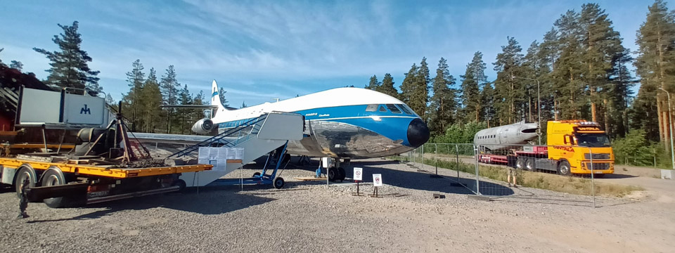
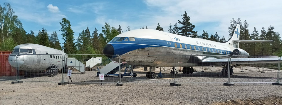
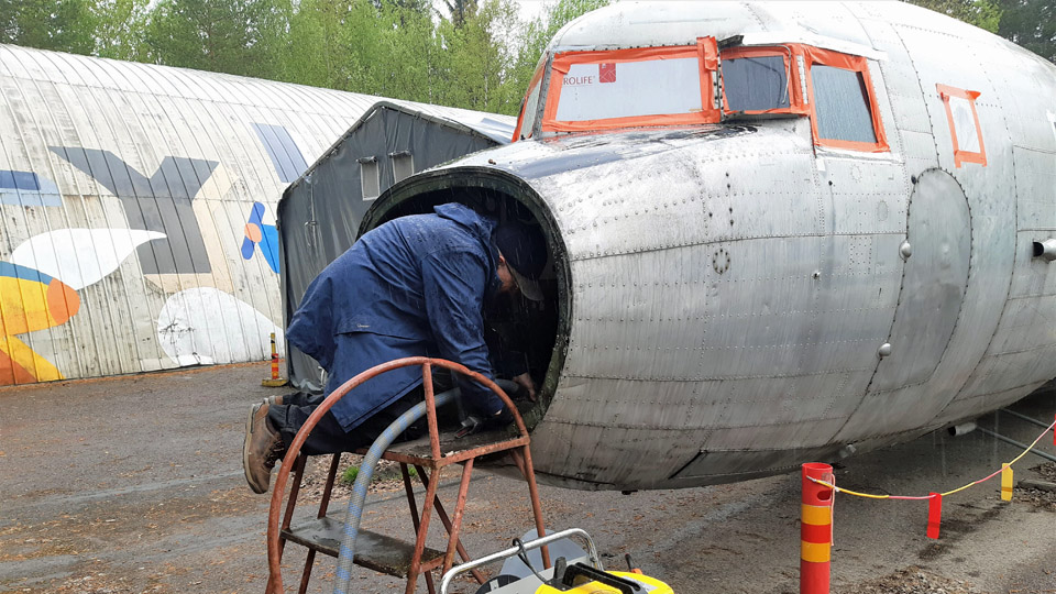
A strike force of Tuesday Club members set off from the Finnish Aviation Museum to Turku Airport to fasten the covers to the DO-5 tail at the end of October. The covers and other equipment came along in a trailer. The DO-5 fuselage is on display beside the Caravelle III, restored as Finnair’s “Bluebird” (OH-LEA) in the vicinity of Turku Airport Passenger Terminal. After arriving at the Airport we got the covers made of aluminium plate and other necessary tools and a ladder out of the trailer got on with the job.
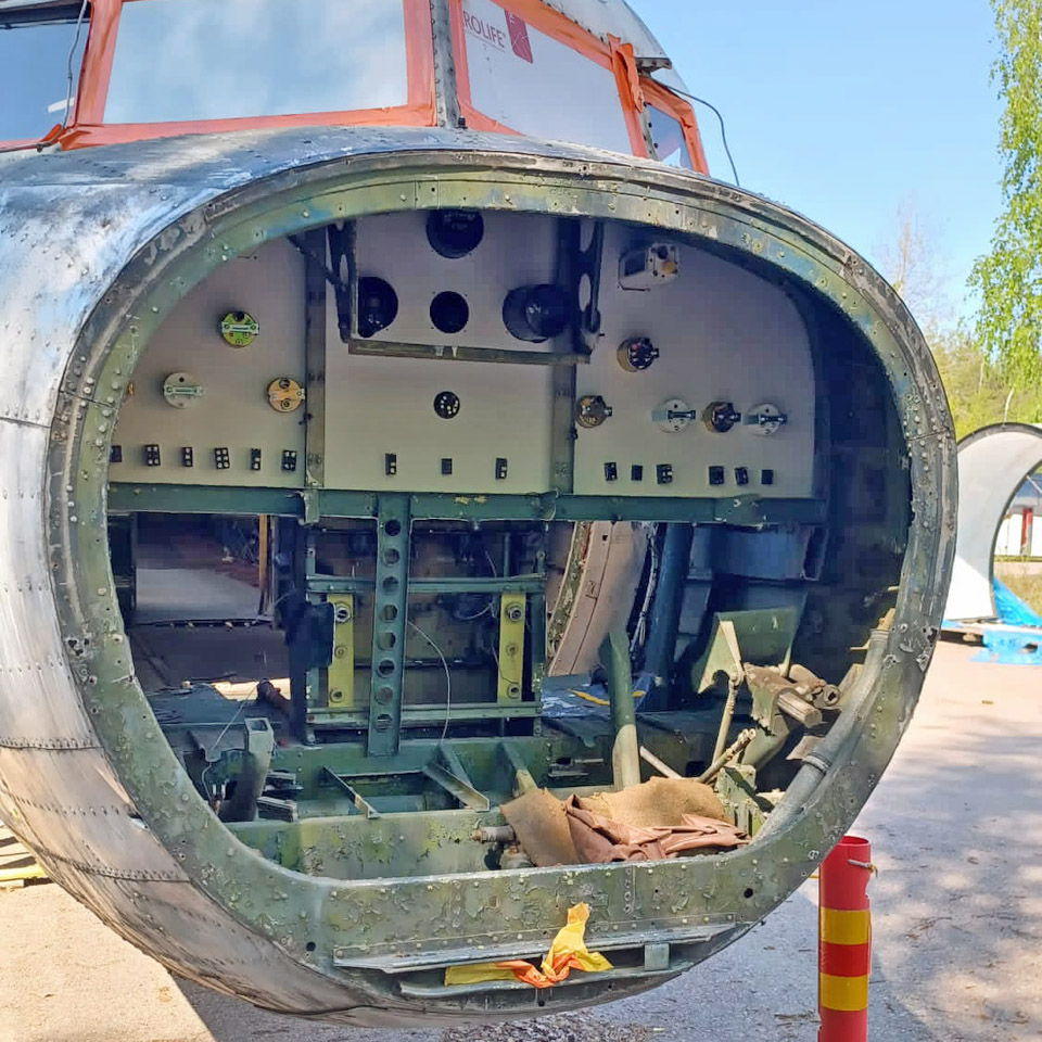
We divided into suitable work groups. One of them fastened the ILS look-alike antenna and the thermometer probe we had brought with us for the DO-5. These were fastened in their original places on the undersurface of the nose cone.
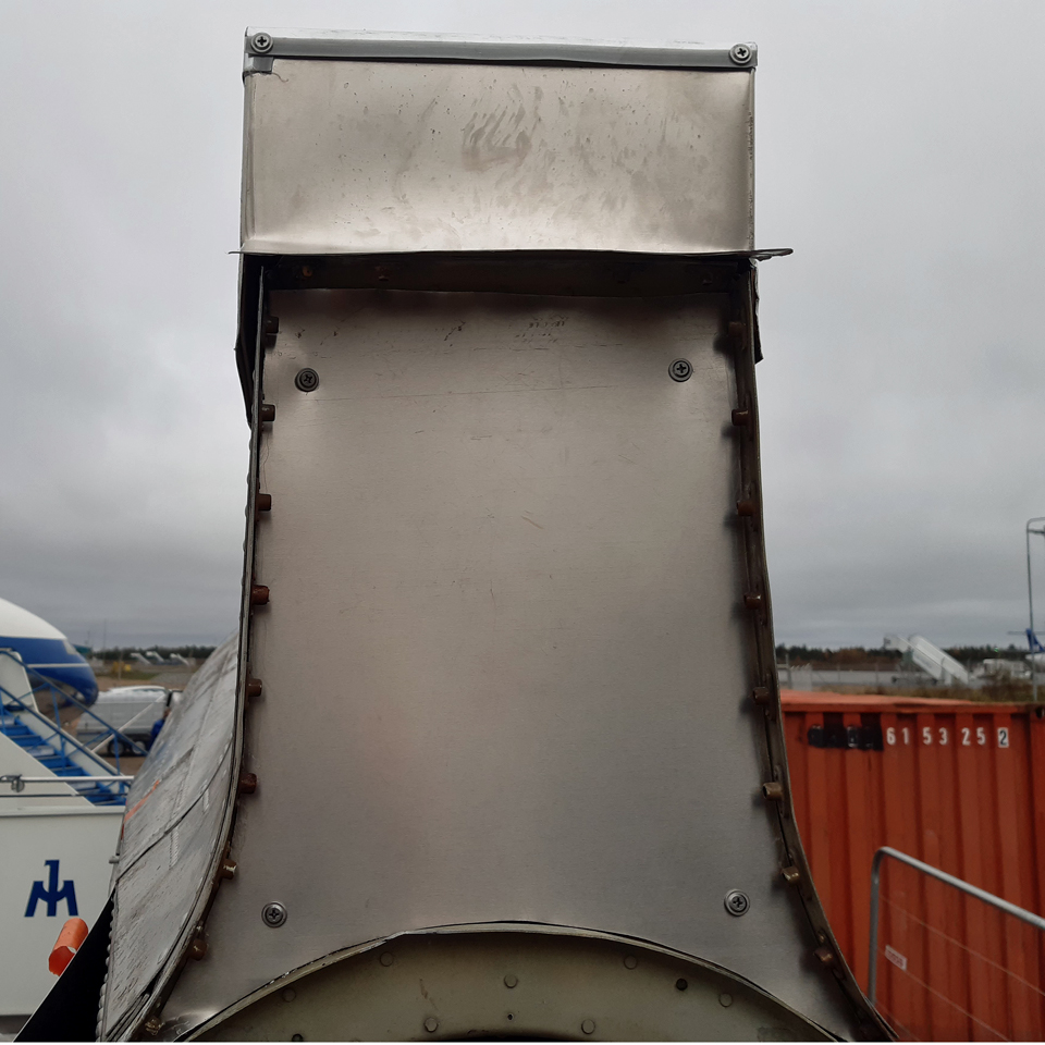
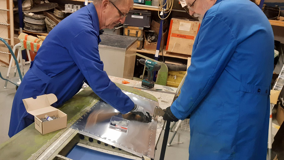
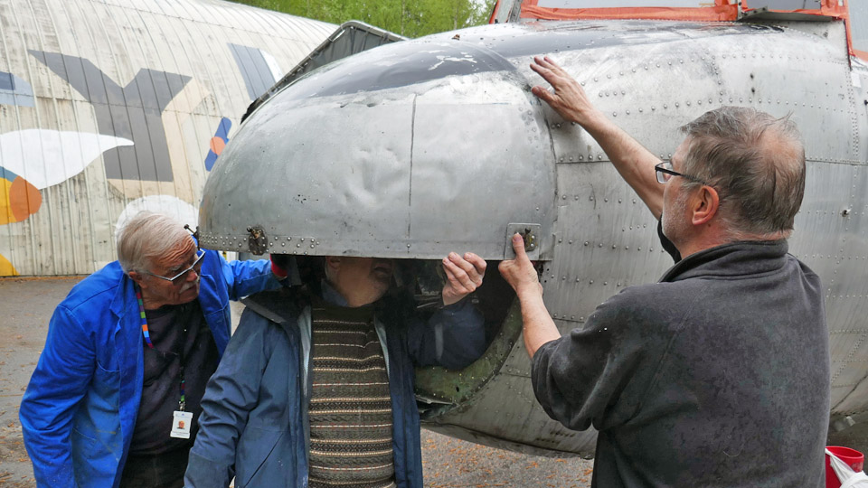
Another working duo started to fasten the covers for the openings of the right- and the left-hand side horizontal stabilizers. The third pair concentrated on fitting the covering shields for the tail cone. The fourth pair was tasked to fit in place the covering case we had built to cover the vertical stabilizer fastening point and to fasten in place the shaped hood, made of thin aluminium sheet, to protect the front end of the case and the fixed fuselage fin at their seam.
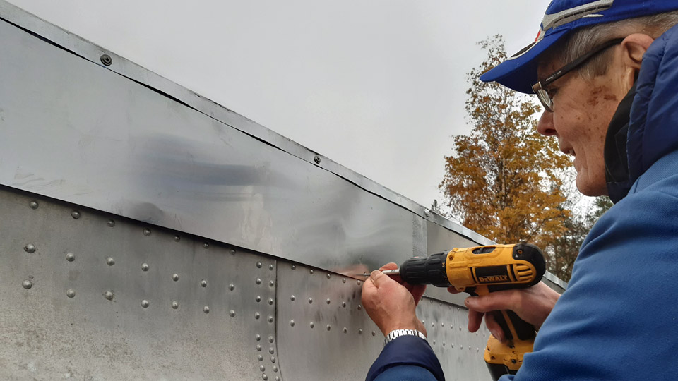
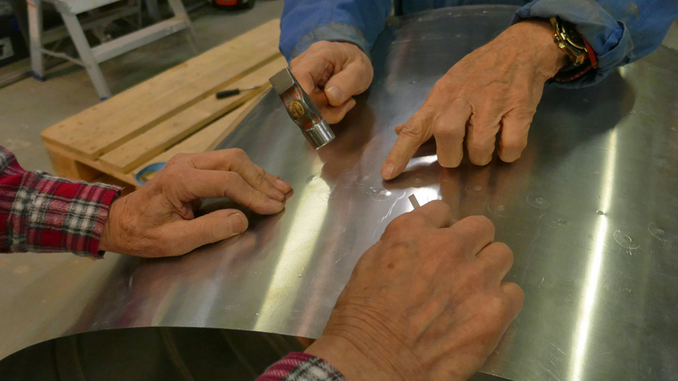
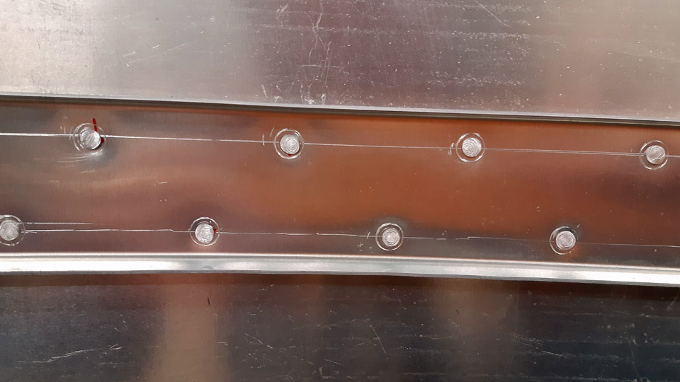
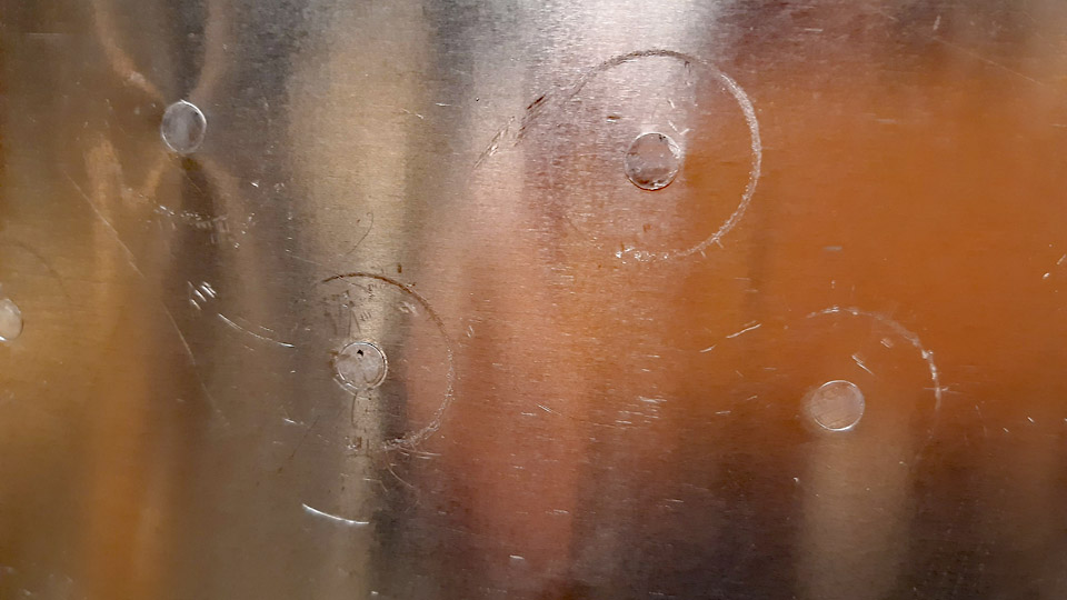
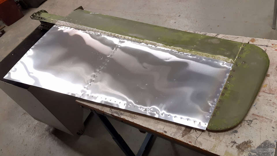
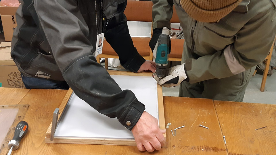
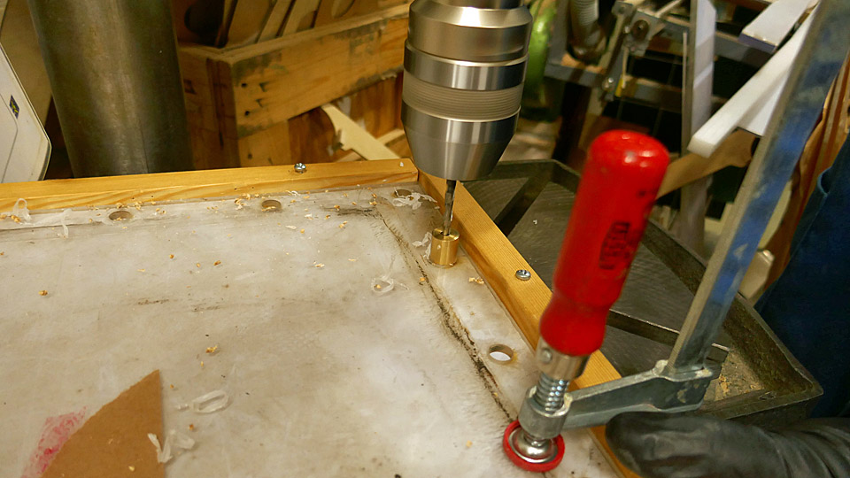
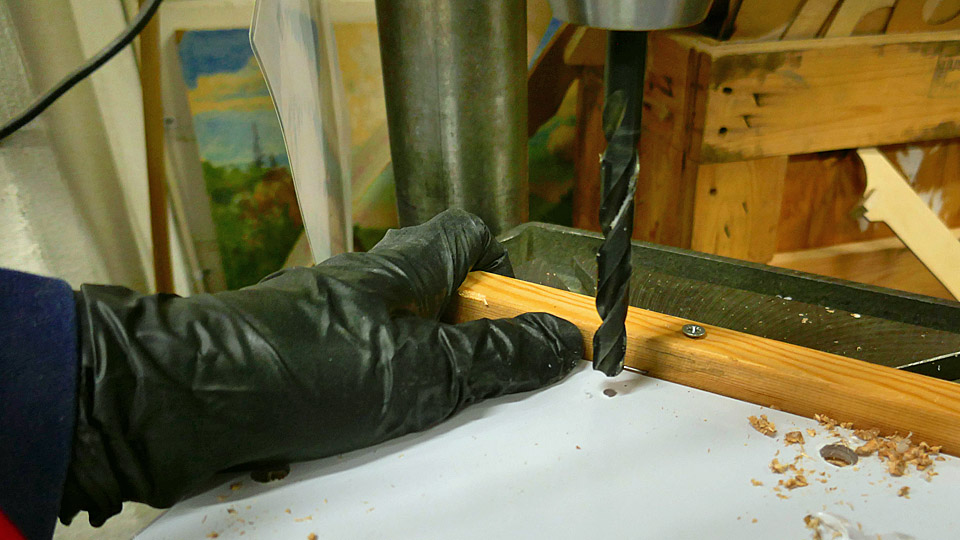
The fitting advanced rapidly, because the covers made at the Museum’s restoration workshop according to blueprints, settled in place as we had planned. The horizontal stabilizers’ covers were fastened to the edge of the opening at their top edge with stainless steel screws. Holes were drilled through the covers into the fuselage for the screws. After this the cover was fastened to the fuselage also from its lower edge. We used stainless steel screws deliberately, so that they won’t start leaking rusty streaks along the fuselage surface as time goes by. An extra bit had to be cut off from the rear end hem of the left-hand horizontal stabilizer’s cover, to get the cover to press tightly along the edges of the horizontal stabilizer’s opening.
When thinking about the way to fasten the covers, it occurred to us that we could have utilized the existing holes in the fuselage. However, it would have been extremely difficult to match exactly the fastening holes in the cover with the holes of the horizontal stabilizer fastening screws. That’s why we ended up with the above-mentioned method, which produced a few extra holes in the fuselage. If the DO-5 were to be made airworthy, the method would have certainly been different.
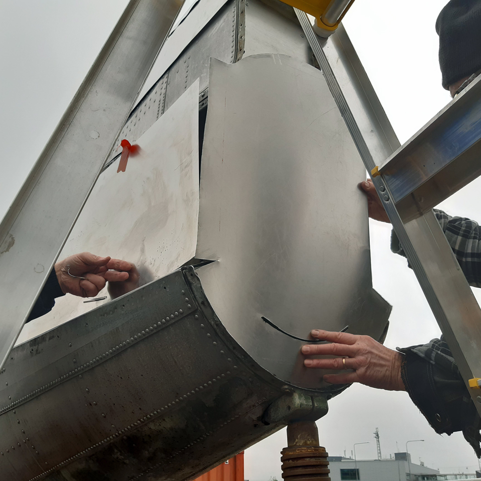
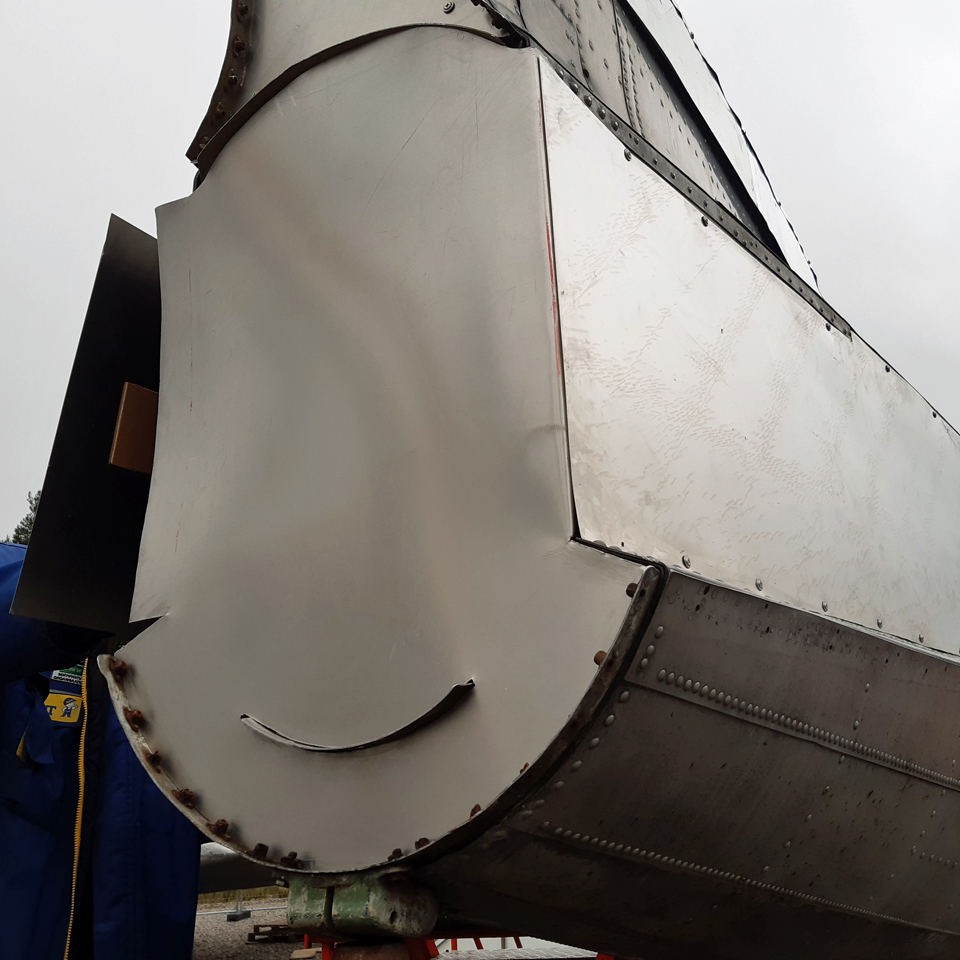
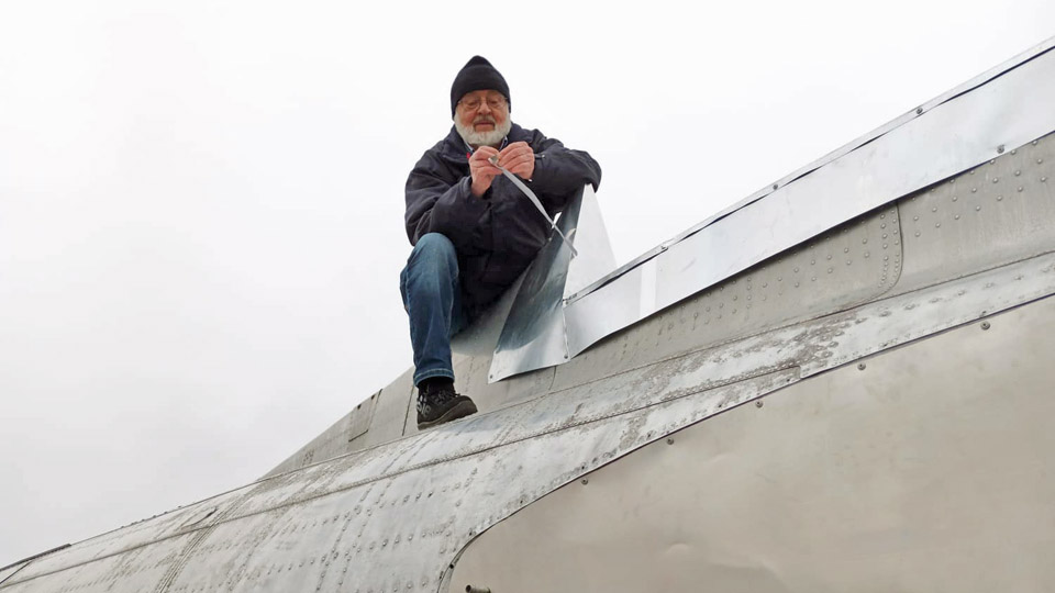
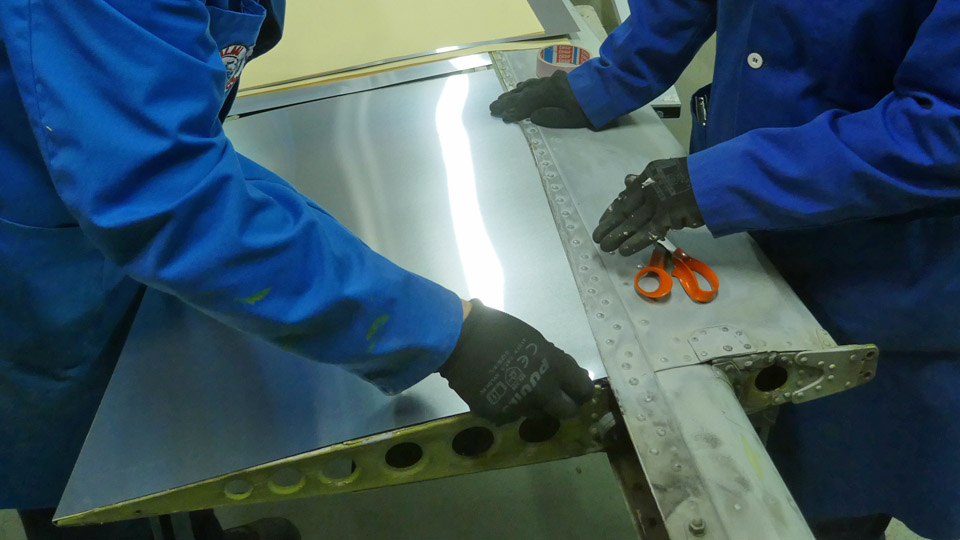
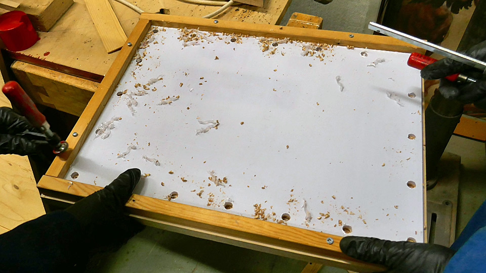
The tail without the tail cone was protected with two separate aluminium covers. We had to shape the edges of the upper cover a bit before it clicked into place and was fastened with a few screws. We also had to shape with a hand drill the curved opening in the lower cover, so that we could get the protuberant strip in the fuselage to “pop out” through the opening and press the cover tightly against the end of the fuselage. This cover, too, was fastened with a few stainless-steel screws. The edges of the lower cover shielding the rear fuselage were bent at 10 cm width to an angle of 90 degrees. This way the sides of the cover could be pushed under the covering sheet of the horizontal stabilizer’s rear end and linked to it with a couple of screws.
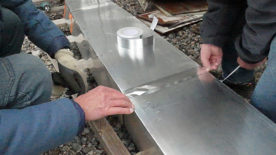
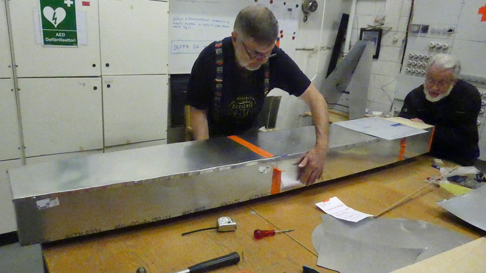
The vertical stabilizer’s fastening point wasn’t covered with just an aluminium cover, like the other openings, but a nearly three metres long covering case was made for it. The seams of the aluminium sheets were covered with duct tape, after which the case was lifted to place on the low support braces of the fastening point. It was noticed that the case settled in its place as planned. The rear end of the case’s aluminium sheet was bent from its lower edge to form a canopy against rain on the rear end of the fuselage. Despite the case being fairly heavy, it was fastened by its hem with a few screws to the fuselage. Thus not even a strong gust of wind gets to throw it from its place.
Photo by Mikko Jaakkola
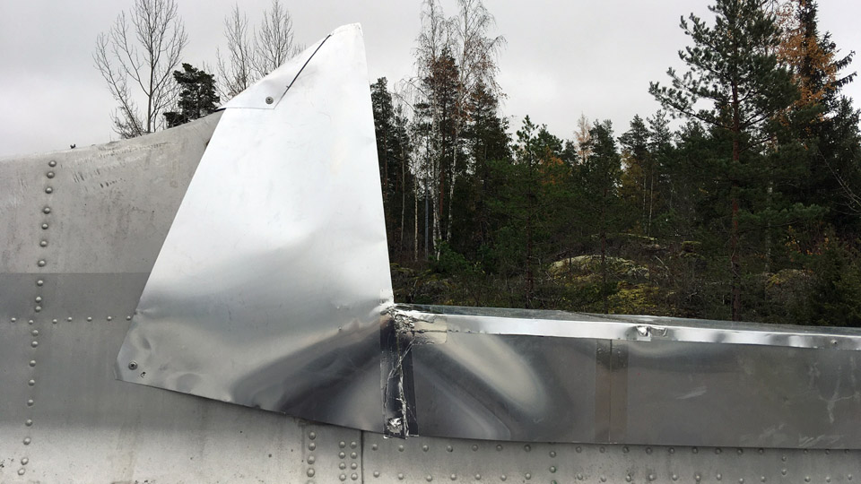
Photo by Esko Ruohtula When the protecting case of the vertical stabilizer’s fastening point was in place, we started work on the final shaping of the hood, covering the joint of the case and the fixed fin. The hood had been bent to its preliminary shape from 0,3 mm thick aluminium sheet at the Museum. We had to shorten it quite a bit before it was the right size to protect the joint. The hood was fastened from its lower edge to the fuselage with a few screws and the sharp head of the hood was shaped round.
Photo by Mikko Jaakkola The openings for the DO-5 horizontal stabilizers, vertical stabilizer and the fuselage rear end had now been protected against the weather, and we could start the home journey to the Finnish Aviation Museum, satisfied with our work. Photos by Lassi Karivalo except if otherwise mentioned. Translation by Matti Liuskallio |
|
Avainsanat: aviation history, restoration, Tuesday Club, DC-3, C-47, DO-5 |
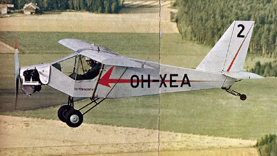
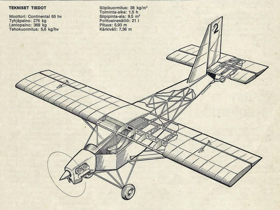
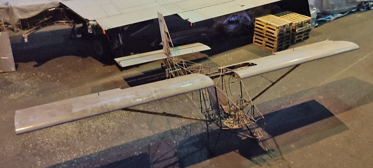
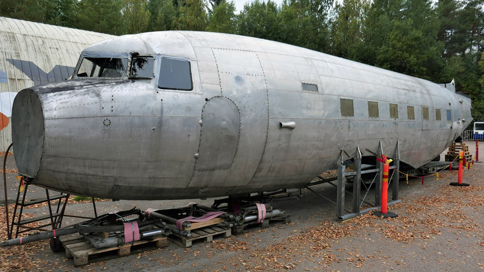
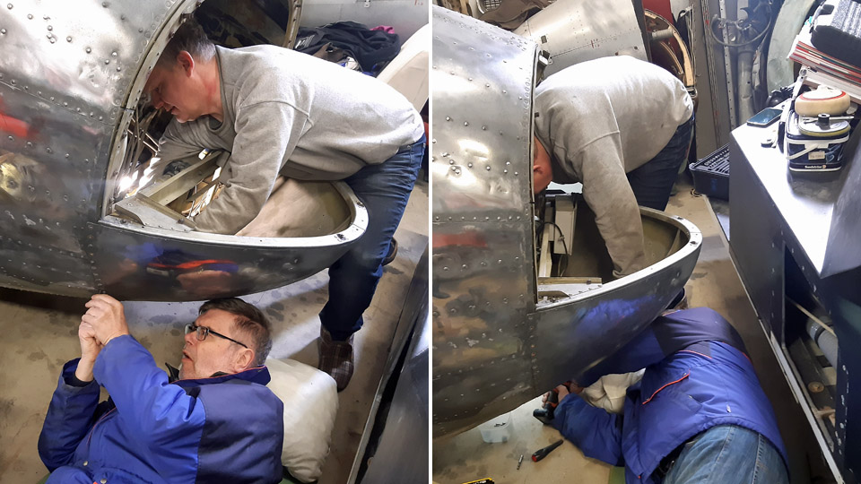
Hietanen OH-XEA "Ressu" to be restored by the Tuesday ClubPerjantai 10.11.2023 - Tuesday Club member Last year Aviation Museum Society Finland was donated a single-seat experimental aircraft, designed and built in the 1960s by Esko and Ari Hietanen, two brothers from Turku. The aircraft was inspected and registered in the civil aircraft register on August 13th, 1969, with the registration OH-XEA. The aircraft, nicknamed Ressu (meaning Snoopy), is a high-winged, mixed structure single-seat aircraft. The tubular framed fuselage is fabric-covered. The wings, ailerons, vertical stabilizer and rudder have wooden structure and plywood covering. The rudder is tube-structured and fabric-covered.
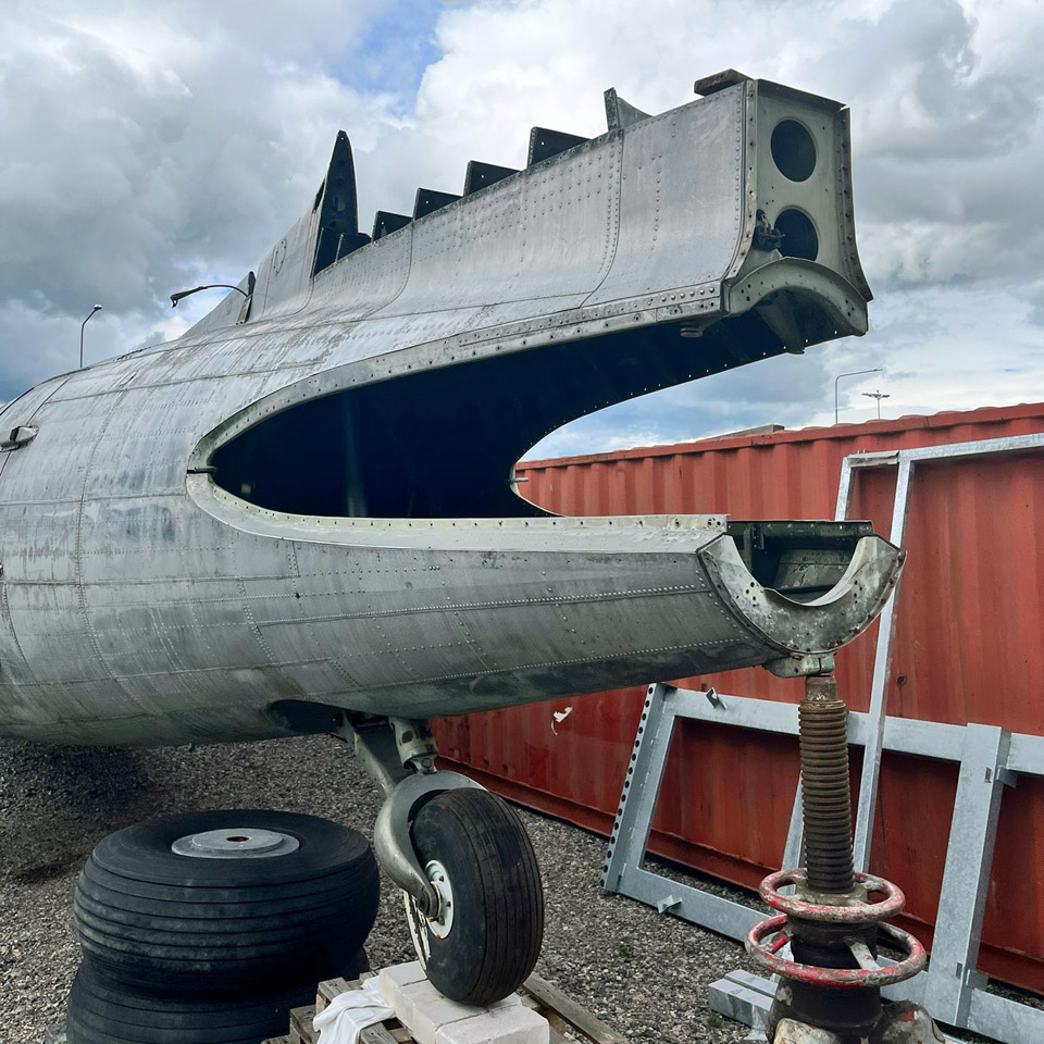
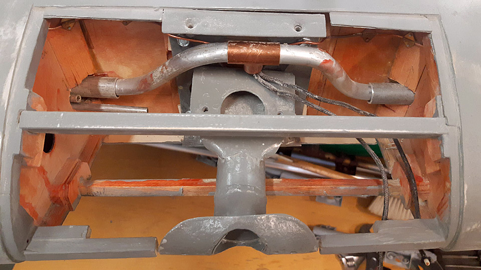
Photo via Aviation Museum Society, Finland. Ressu is a small aircraft. Its wingspan is 7,4 m and the fuselage is 5,5 m long. The widest part in the fuselage is the landing gear, with 1,4 m from one end of the axle to the other. In its time, Ressu had several registration marks. First it was registered as H-EA (Hietanen Esko and Ari), then OH-HEA and eventually OH-XEA when it was approved in the civil aircraft register. Ressu’s engine was Continental A 65. The aircraft was removed from the civil aircraft register on January 1st, 1973. We don’t know how many hours Ressu has flown.
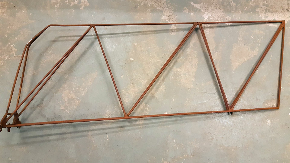
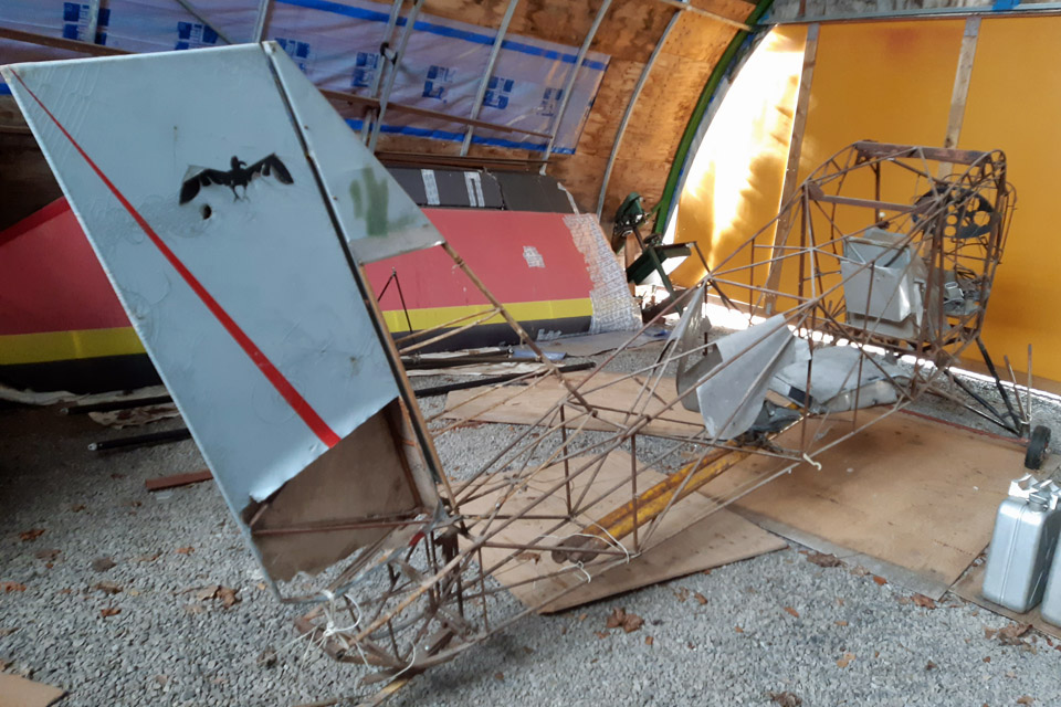
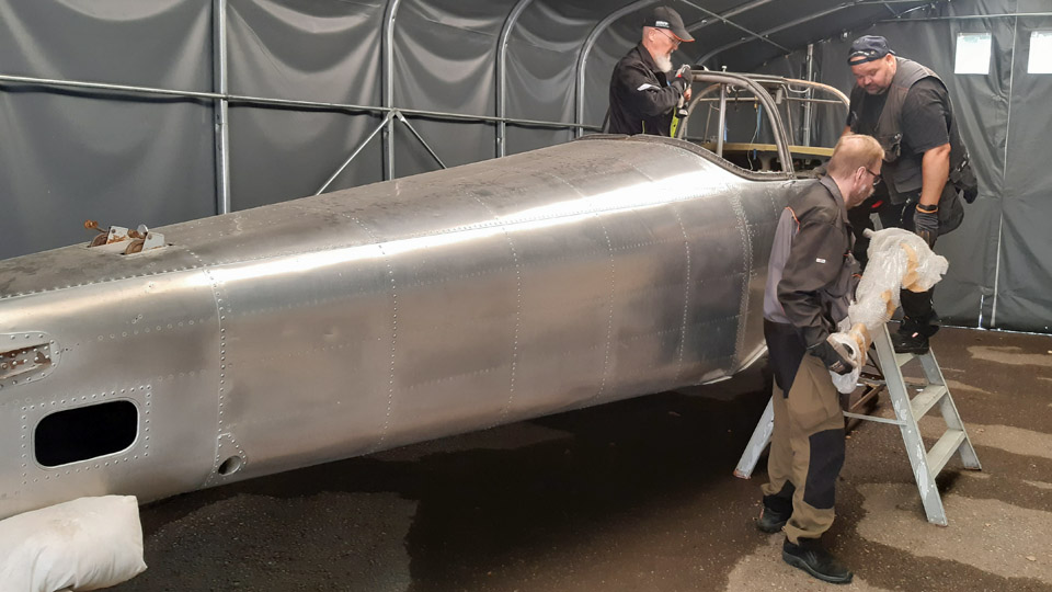
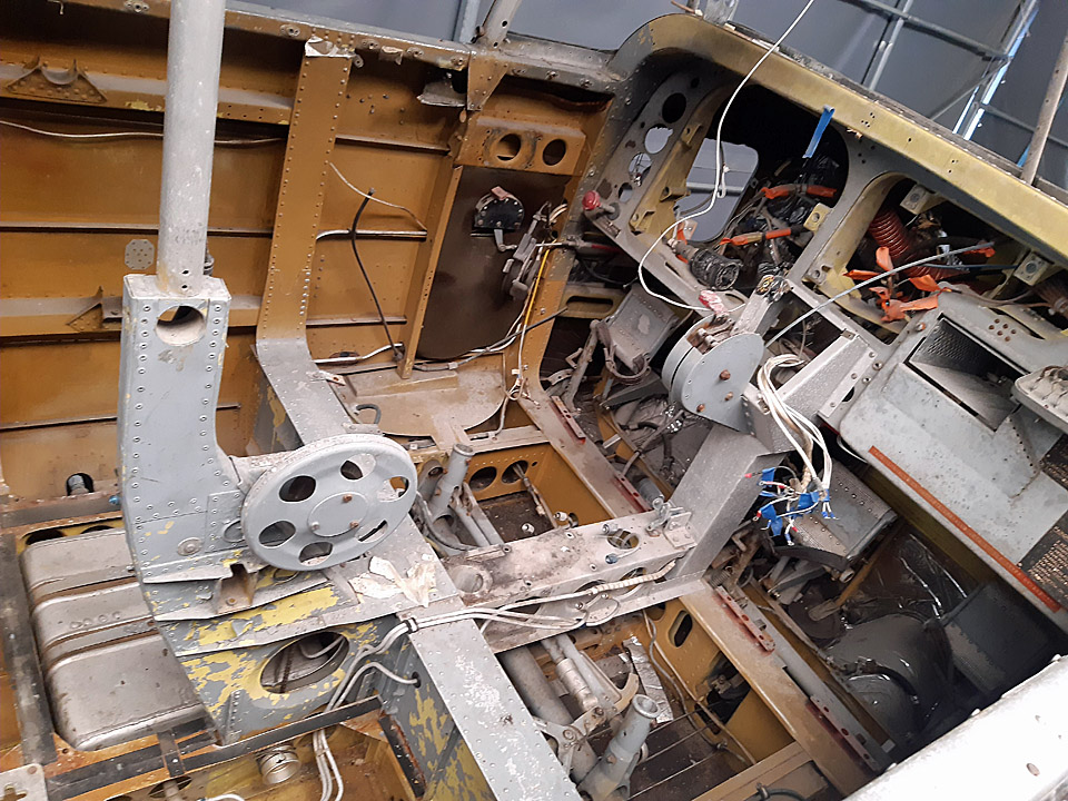
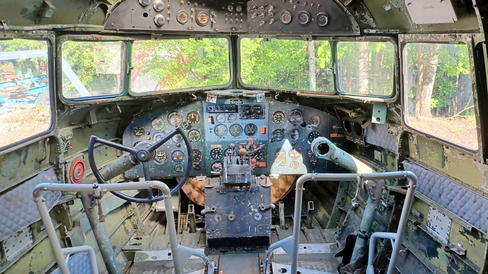
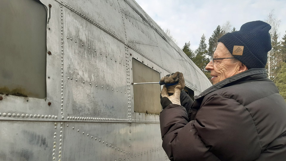
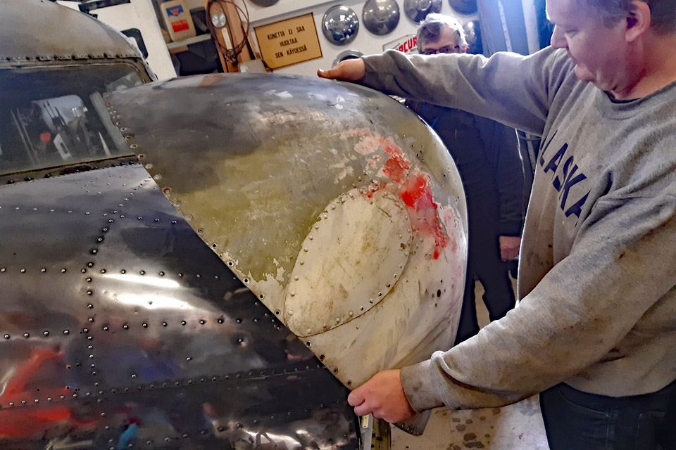
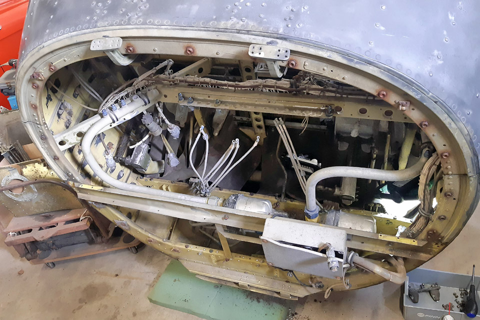
Photo via Aviation Museum Society, Finland. After the flying activity ended, Ressu was stored in several places and its fuselage was badly damaged. Today the fuselage has no traces of the fabric covering and the tubular frame is covered in heavy rust. In the cockpit there is just the pilot’s seat, control stick, pedals, and an empty instrument board. The engine, the instruments from the cockpit panel and the landing gear wheels have all disappeared during the years. Out of four wing struts only three remain. The wings were painted pale blue, the horizontal stabilizer and the elevator have been preserved quite well, there are only some damages on the plywood covering. The fabric covering of the rudder is broken and the paint on the fabric is badly crackled. The fabric covering on the fuselage has probably been painted pale blue as the wings.
The aim is to restore Ressu at the Tuesday Club to resemble its appearance in 1969 when it was registered. This means that the plywood covered surfaces of the wings and parts of the tail will have to be cleaned and the damages repaired. After that we can consider restoring the fuselage. There the first step would be to treat the rusty fuselage before covering it with fabric. We will try to find instruments for the cockpit if we are able to find the kind of instruments Ressu had. The engine could well be a discarded and inoperative Continental A 65, if we could find one.
Photo by Elias Viitanen.
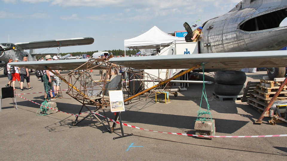
In autumn 2022 Aviation Museum Society Finland volunteers assembled Ressu in the former shipyard hall in Pansio where the Caravelle III, owned by the Society, was under restoration. Ressu was also on display at the Society’s stand in the Turku Airshow in June.
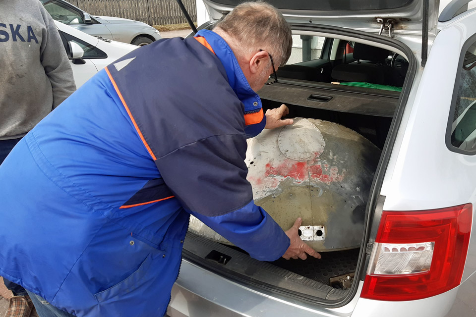
After that Ressu has been stored at Lemu, in the Turku area. From there we fetched Ressu’s wings, horizontal stabilizer, elevator, rudder, tail wheel assembly, fuel tank and wing struts, and brought them on a trailer to the Finnish Aviation Museum in Vantaa. In the Museum’s restoration workshop the Tuesday Club members have already started the restoration of Ressu’s parts. The fuselage remained at Lemu, but it will probably be taken under restoration next year. The Tuesday Club has now started Ressu’s restoration project which is estimated to take a couple of years. Photos by Lassi Karivalo except if otherwise mentioned. Translation by Erja Reinikainen. |
|
Avainsanat: aviation history, restoration, Tuesday Club, Hietanen HEA-23b, OH-XEA, "Ressu" |
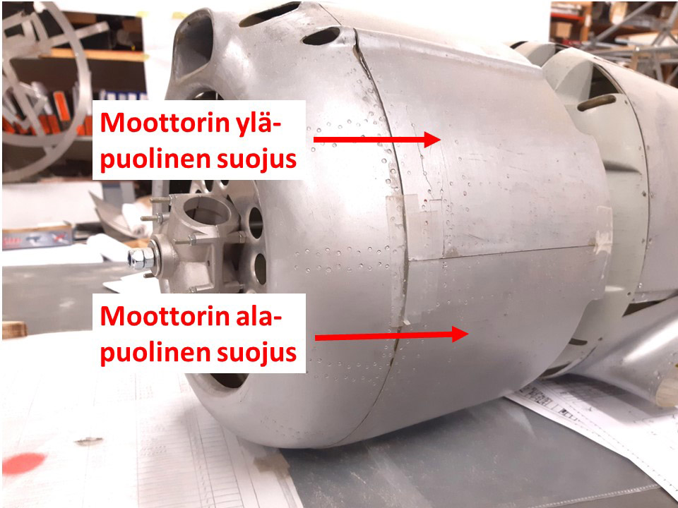
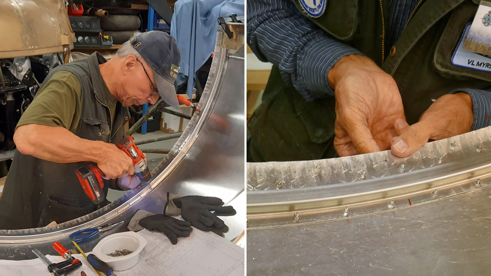
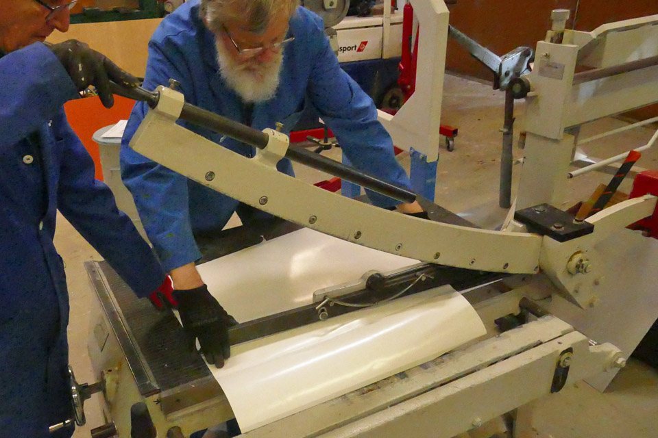
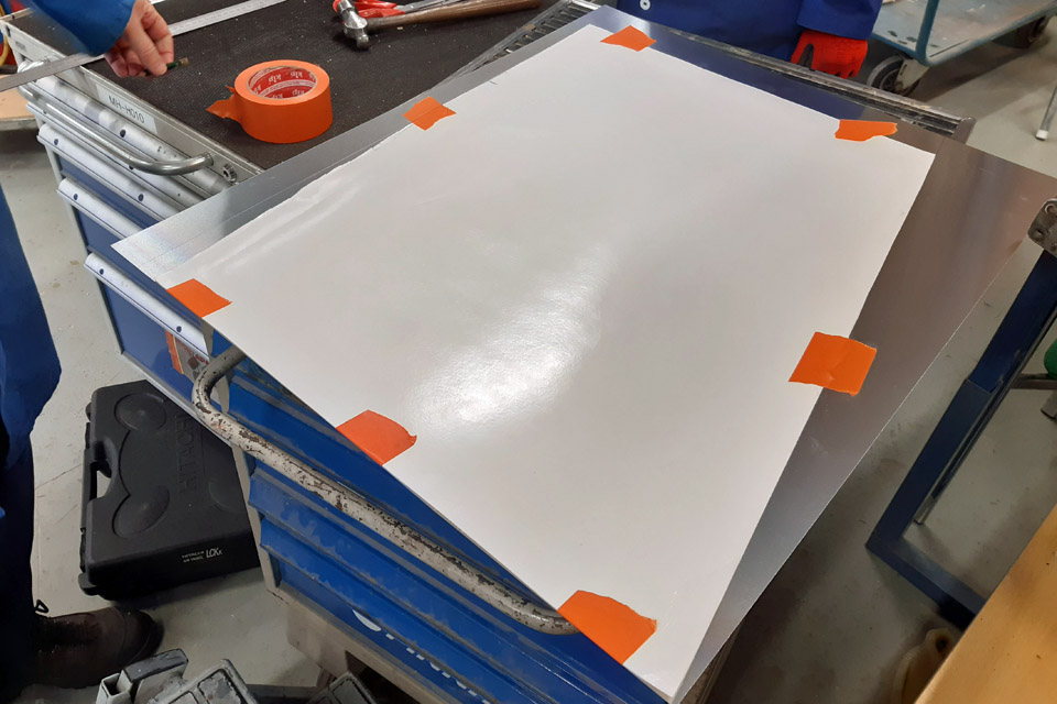
Making the lower sheet metal cowling for the Myrsky engineMaanantai 6.11.2023 - Tuesday Club member The VL Myrsky II (MY-14) engine has a lower and upper cowling, made of sheet metal. The lower cowling was built at the Tuesday Club. The cowling was made of 1 mm thick aluminium sheet. The stiffening formers that were fastened on the inside surface of the cowling were made of the same material. The upper engine cowling will be built at the Finnish Air Force Museum, where the main undertaking will be the restoration of the MY-14 fuselage.
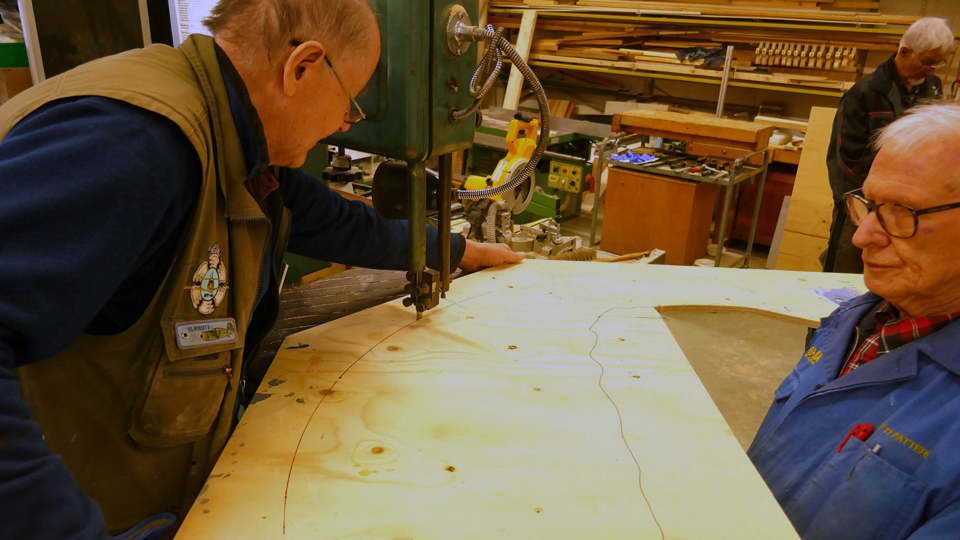
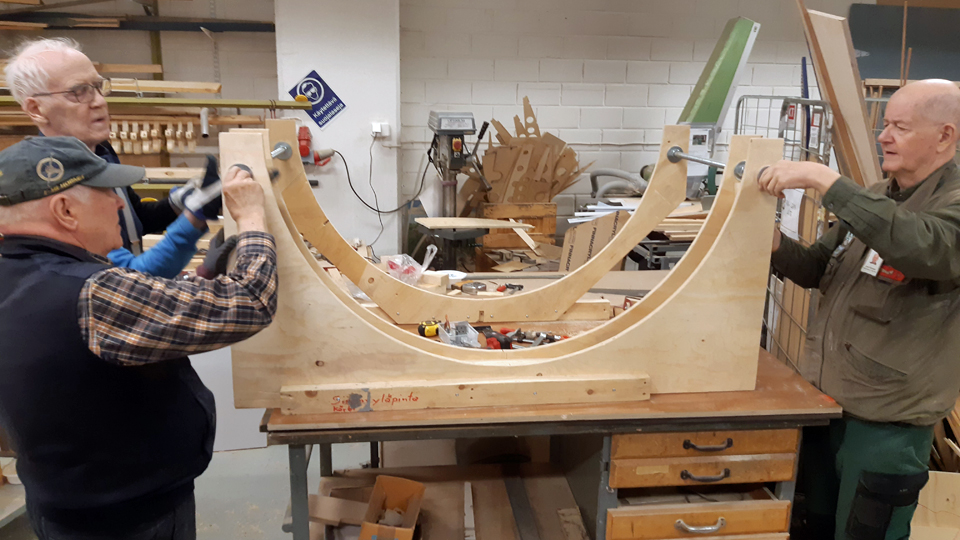
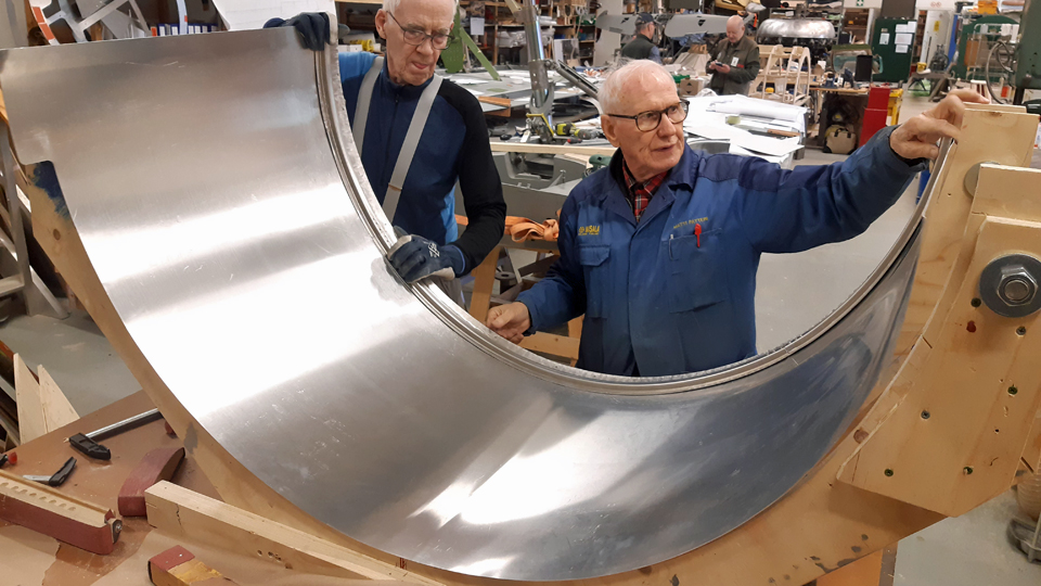
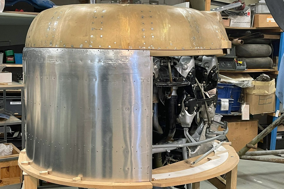
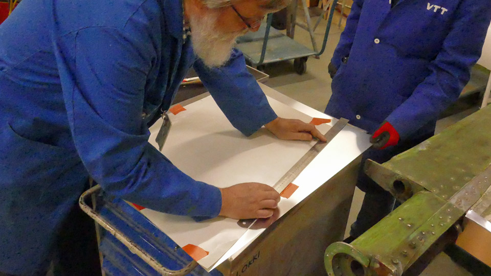
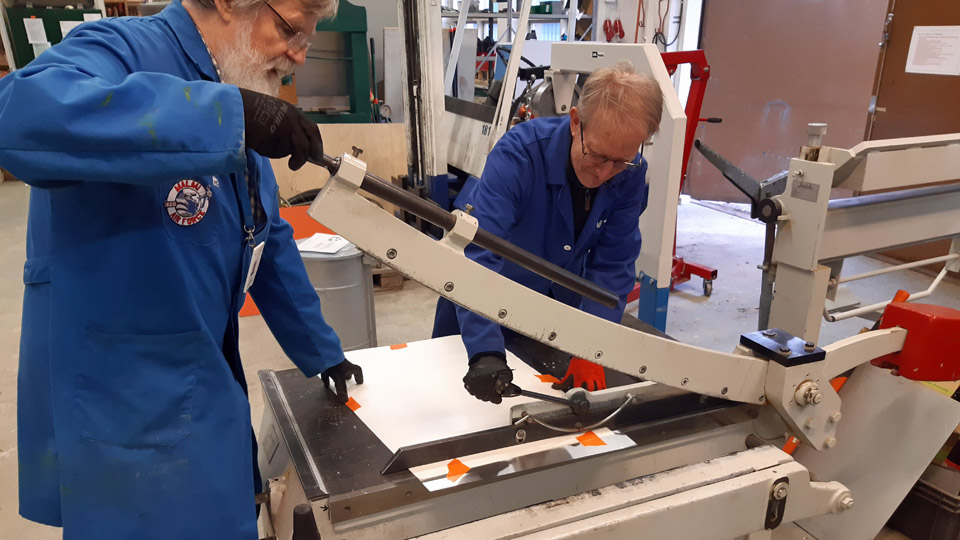
Before the 1 mm sheet, cut out of aluminium plate, was started to be formed into the U-form of the lower engine cowling, a female forming last was cut out of sturdy plywood. This forming last works as a model, showing that the lower engine cowling needs a curved shape. The shaping of the sheet was done by mangling the sheet in a mangler with three rollers and comparing the sheet to the forming last at intervals. After the mangled sheet had been made to press itself tightly against the forming last, it had reached its correct form. Next the formed sheet could be tried on the Pratt & Whitney engine used in the Myrsky. The engine was moved into the restoration shop in the Finnish Aviation Museum. We managed to fit it snugly on the side of the engine.
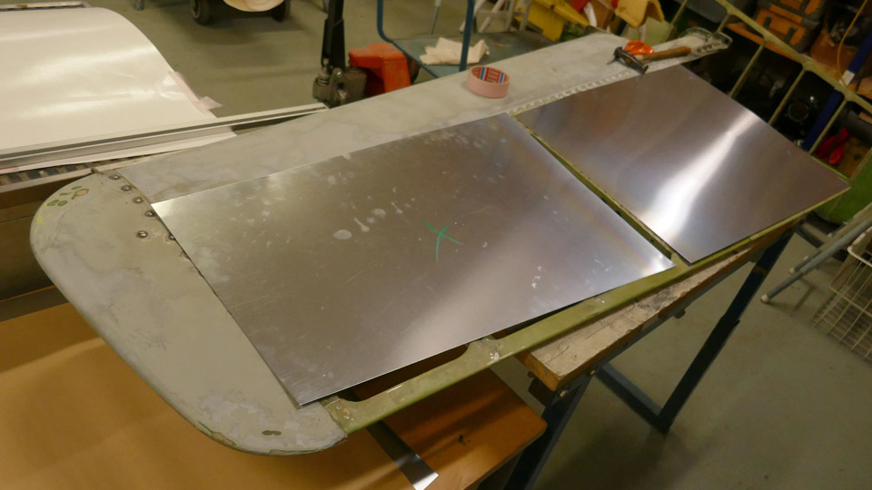
Photo by Heikki Kaakinen. The lower engine cowling needs several stiffening profile strips to keep it in form. The stiffening strips were cut and bent according to the programming information given at Prolaser Oy. After this we started to fasten the stiffening profiles on the inner surface of the engine cowling. The stiffening strips are fastened by riveting onto the metal casing.
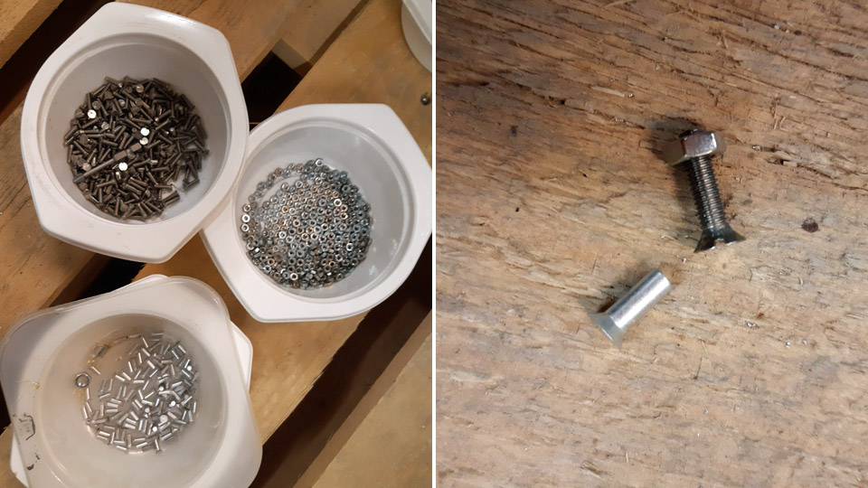
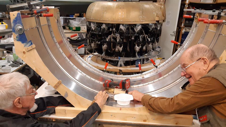
The Myrsky blueprints gave us the exact position of each profile strip on the inner surface of the engine cowling. So we started fastening the profile strips, but not straight with rivets but at first they were fastened in place with 12x3 mm small bolts. The holes for the bolts were drilled on the rivet spots according to the blueprints, and a small bolt was put in the hole to fasten the stiffening strip to place. When all the profile strips had been fastened, the inside of the engine cowling looked a bit like a porcupine, because the nuts of the small bolts were sticking out of the edges of the profile lists.
Now the engine cowling with stiffening profiles was fitted on the engine. The casing still settled laudably in place, so we could start fitting the fastening latches in the top part of the engine cowling. The lower and upper engine cowlings are fastened to each other with openable latches because the cowlings have to come off when maintaining the engine or armament.
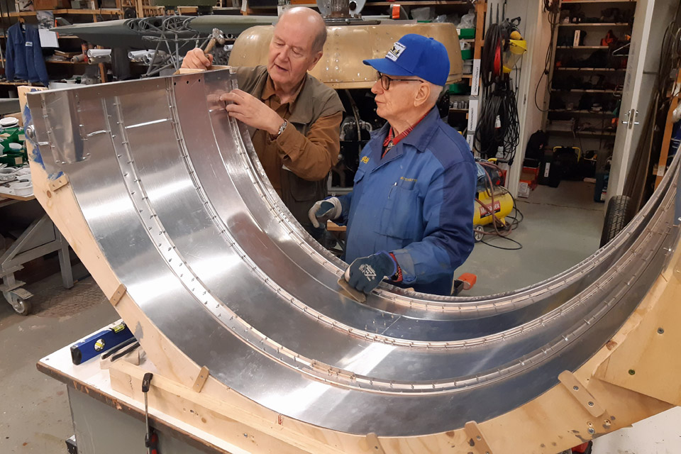
Before we started changing the fastening bolts of the stiffening profiles to countersunk aluminium rivets, the outside holes of the bolts were countersunk to suit the flush rivets. The profile strips were riveted, one hole after the other, onto the engine cowling’s inner surface with 8x3 mm aluminium rivets. The riveting was done with a riveting pin and a counter part pressed on the rivet head on the opposite side.
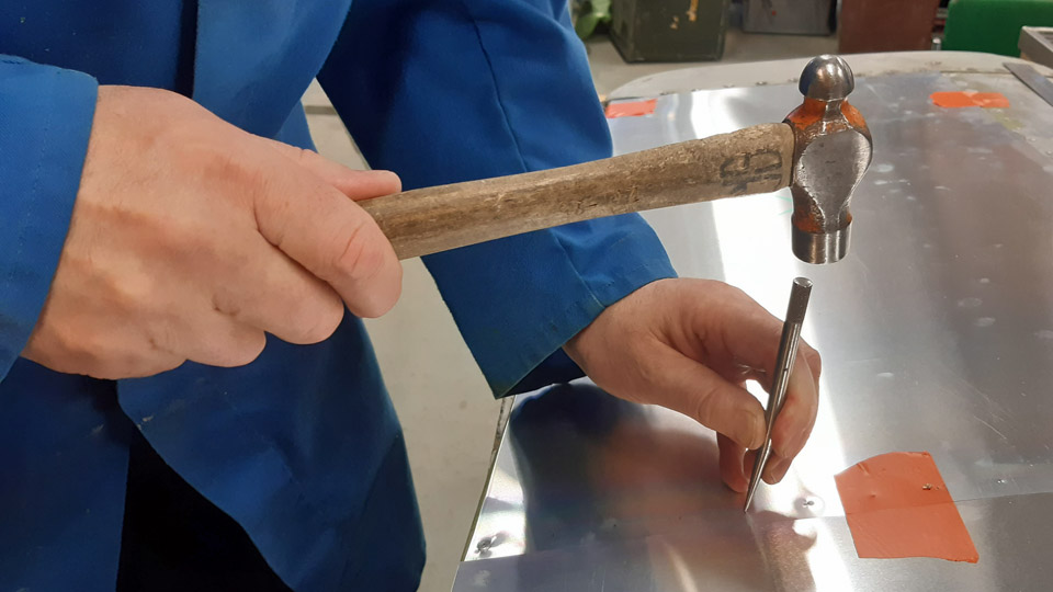
Finally it was checked that the flush heads of the rivets had been riveted flush with the engine cowling surface. Some rivet heads had to be tapped with a hammer flush with the engine cowling surface, so that the outside surface of the cowling was left absolutely smooth after the riveting. The finished lower engine cowling will still be chromated, the same way as all the Myrsky aluminium parts. Photos by Lassi Karivalo expect if otherwise mentioned. Translation by Matti Liuskallio. |
|
Avainsanat: aviation history, restoration, MY-14, VL Myrsky, Tuesday Club |
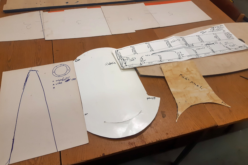
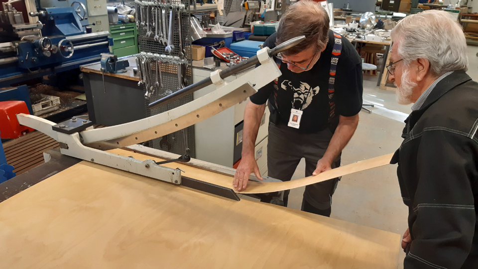
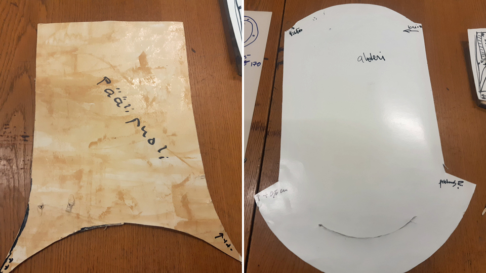
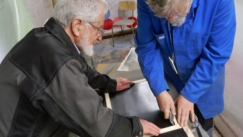
Constructing the weather shields for the stabilizer openings for the DO-5 (Douglas C-47)Lauantai 4.11.2023 - Tuesday Club member The fuselage of the Douglas C-47 (DO-5) owned by Aviation Museum Society is situated in vicinity of the Turku Airport passenger terminal, close to the Caravelle III, magnificently restored as Finnair “Bluebird”. The DO-5 tail has no elevators or rear cone. That’s why rainwater and snow blizzards have penetrated into the fuselage for years, to play havoc inside. Now we can get rid of this problem when the Tuesday Club has made shields to cover the openings. To build them we visited Turku to measure the sizes of the openings and cardboard templates were made. (see the blog from Sep.21st 23)
Photo by Ismo Matinlauri
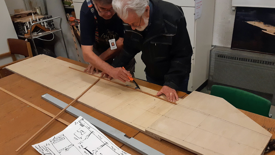
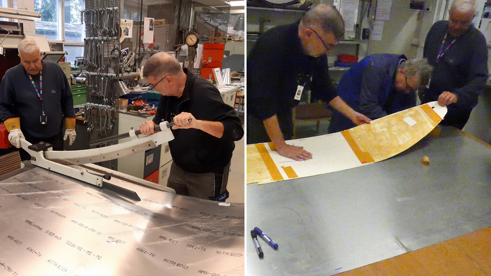
When we were starting to build the covering shields, we contemplated, whether we’d build the shields from plywood, or thin aluminium sheet. We ended up with a compromise, where we would build a plywood case covered with aluminium to shield the vertical stabilizer’s fastening point. The openings of the horizontal stabilizers and the rear openings we would shield with aluminium sheets. Building the vertical stabilizer covering caseThe fastening point of the vertical stabilizer is built in such a way that it can’t be covered with a shield alone. That’s why we’ll be building a covering case from plywood, which can just be pressed into place, supported by the fastening point’s 10 cm high supporting brackets. The top of the case will be built from sturdy plywood plate. The sides will be from thin plywood. Because the plywood we use isn’t weatherproof, we’ll cover the plywood case with thin aluminium offset-press sheet, which goes well with the aluminium fuselage of the DO-5.
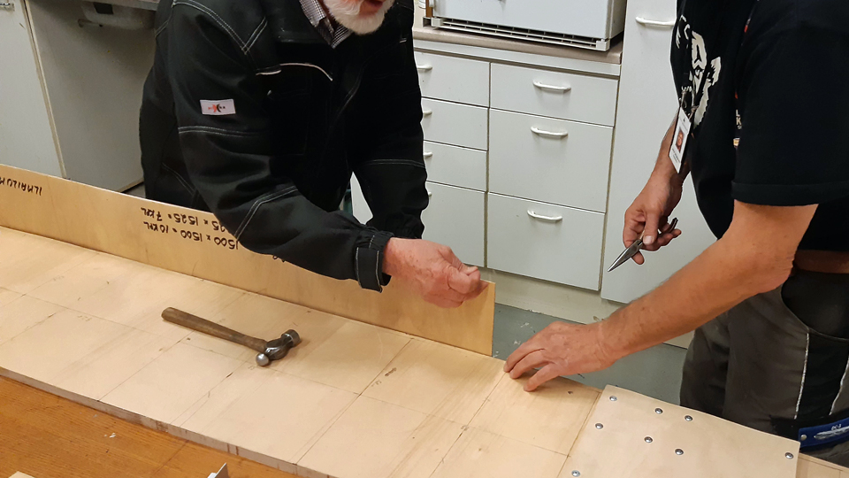
The construction of the covering case of vertical stabilizer fastening point was started from the top, which duplicates as the frame of the case. To make that we used sturdy 12 mm thick plywood plate. We had to build the top from two joined pieces, because the length of the plywood plate at our disposal wasn’t enough to cover the 240 cm length of the vertical stabilizer’s fastening point.
We cut two pieces of plywood, which were a bit broader than the fastening point of the vertical stabilizer. The pieces were joined with a 30 cm long plywood joint piece. The form of the fastening point was drawn according to the blueprint on the more than 240 cm long case top. After that the extra bits according to the drawing line were sawn off, so that we had the finished piece of plywood for the top of the case.
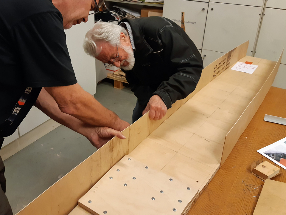
The sides of the case were made from 3 mm thick aviation plywood. 15 cm broad ”strips“ were cut, using a cutter, from the plywood plate to form the sides of the covering case. A 15 cm broad plywood side shields well the vertical stabilizer’s fastening point. The plywood strips were fastened from their upper side to the side of the roof plywood with 20 mm nails. They were joined to one another with a lap joint, so that the ends of the plywood overlapped 10 cm.
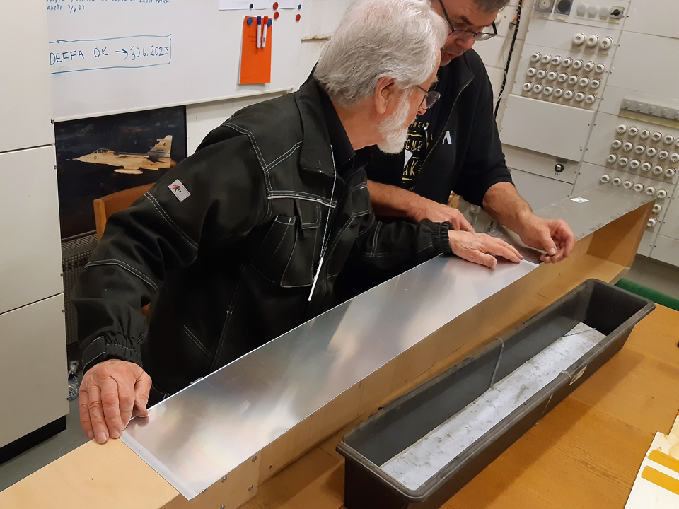
When the vertical stabilizer’s covering case was structurally ready, it was covered with 0,3 mm thick offset printing sheets. From 100x70 cm aluminium sheets at our disposal, we cut off strips that were 1 cm broader than the sides of the case. That way the covering strip reaches a bit past the plywood side forming a “dripping edge”, preventing rainwater from rising into the plywood under the aluminium sheets. The aluminium strips were nailed with 20 cm nails to the edge of the 12 mm thick top plywood edge. The strips were joined with lap joints overlapping about 5 cm. The lap joint will be covered with aluminium tape when the covering case is fitted into place.
After the sides of the case had been covered, the case roof was covered. Three one-metre-long pieces were cut from the offset sheets. The sheets were cut about 5 cm broader than the case roof. This is because the edges of the aluminium sheets will be bent over the roof edge to cover the roof/side plywood joint. As the roof covering sheet had been fastened in place, its edges were bent with gentle beating with a hammer onto the top edge of the side sheets. The overlapping edge of the offset sheet was fastened to the roof edge with a few sheet metal screws. The case covering the vertical stabilizer joint was finished. To shield the front end of the covering case, there will be a tapered “hood”, which will be formed from aluminium sheet. This hood will cover the joint of the vertical stabilizer’s front part (fin) and the covering case. The hood was made from 0,3 mm thick offset sheet and it was bent into form with a bending machine. The so far oversized hood will be formed to its final shape when fitting the vertical stabilizer covering case to the DO-5. Making the horizontal stabilizer opening covers
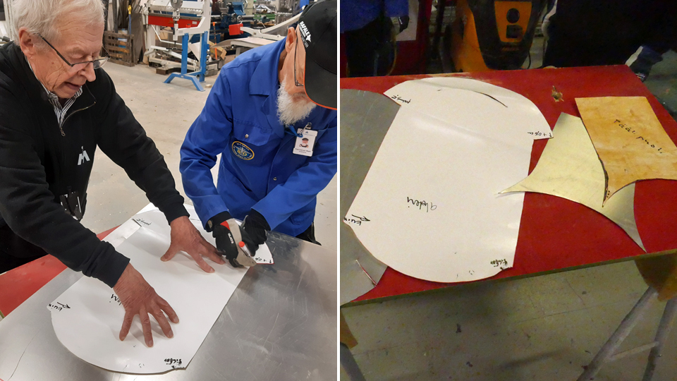
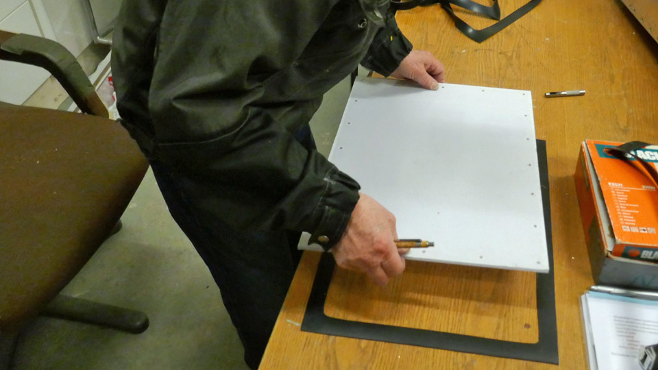
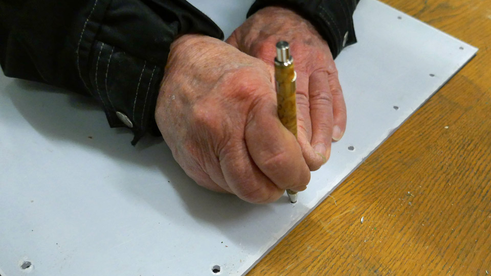
The covers for the DO-5 horizontal stabilizer openings were made from 0,7 mm aluminium sheet. A piece was cut, big enough for both the openings of the horizontal stabilizers. The cardboard template of the openings was fastened on the aluminium sheet with adhesive tape. The outline of the template was drawn on the sheet with a felt pen, along which a billet to cover the opening was cut with a cutter and tin snips. Because the cutter and tin snips left the edges of the aluminium piece jagged and sharp, the edges were smoothed with a file. In a similar way the other cover was also cut using the cardboard template. We presume that the covering pieces we cut, are mirror images and will fit either of the two openings.
At the leading-edge head of the stabilizer opening there’s a fixed pipe for the stabilizer’s anti-ice rubbers’ pressure hosepipe. A hole was cut in the covering shield for the hosepipe. Now we were ready to remove the protective plastic sheets on the covering piece. Any traces of the plastic were washed off with white spirit.
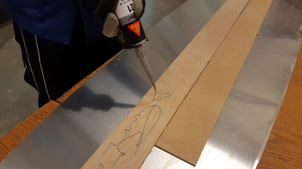
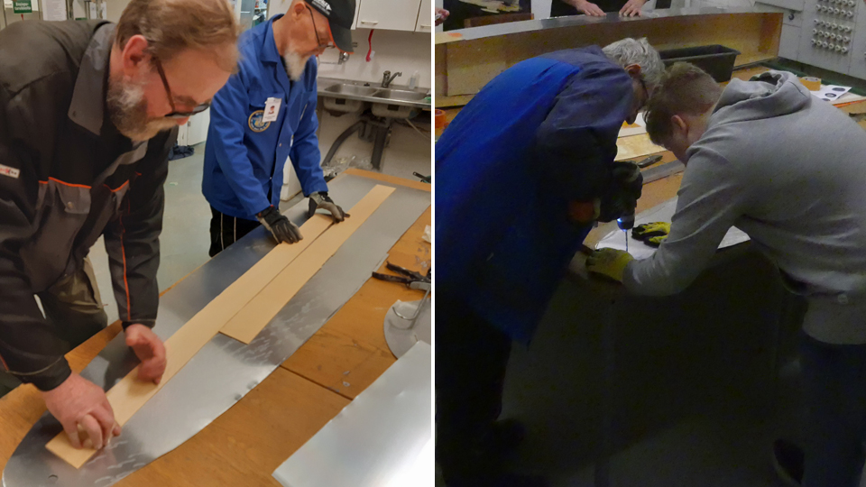
The horizontal stabilizers’ opening covers, cut from 0,7 mm aluminium sheet, are very flexible, so it was decided to stiffen them with strips of plywood. From 3 mm plywood panel about 10 cm wide plywood strips were cut with a cutter. They were glued on the inside of the horizontal stabilizers’ covers using the Sikaflex 221.This way the covers gained suitable stiffness, which facilitates their fitting in place to shield the openings of the horizontal stabilizers of the DO-5. The tail end covering plates
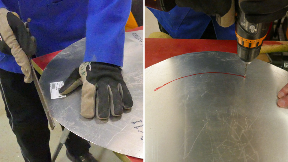
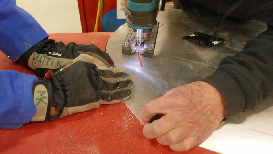
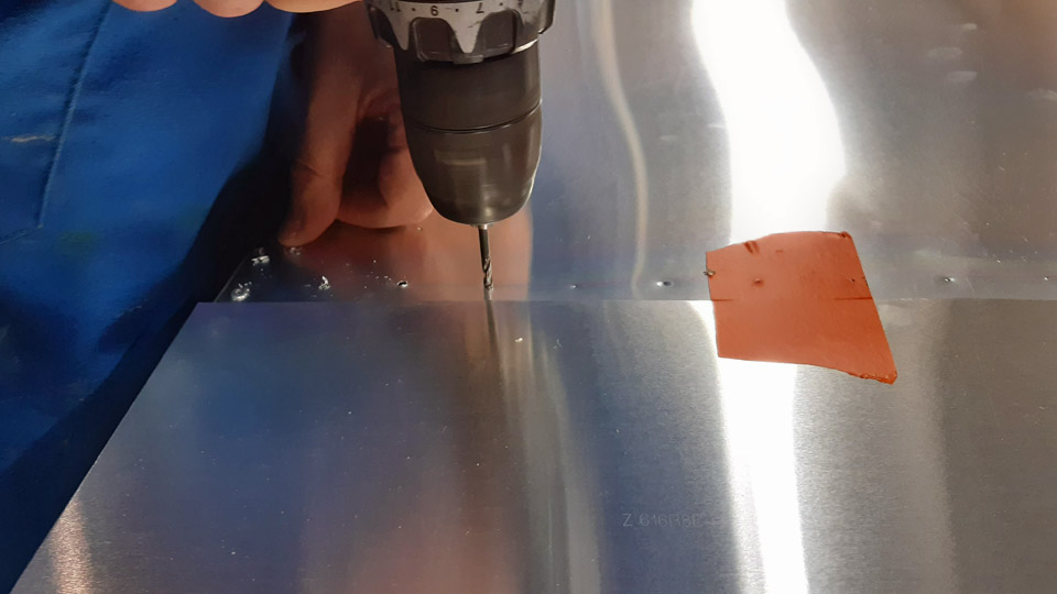
The DO-5 tail is without the tail cone, so the rear end of the fuselage is prone to rain. The rear end will be covered with two aluminium plates, of which the upper is small compared with the lower one. A template from cardboard we had made was placed on the 0,7 mm aluminium plate and the outlines of the templates were drawn on the plate with a felt pen. Covers for both of the rear fuselage openings were cut from the plate. The edges were smoothed with a file. A curved slit a few mm wide had to be made to the lower shield, through which a solid protuberance on the fuselage “peeps” out. That slit was made by drilling a hole to the end of the slit and then drilling the slit open with a keyhole saw.
The covers for the vertical and horizontal stabilizer openings, as well as the rear fuselage, were ready to be fitted to the fuselage of the DO-5. The fittings will be completed yet before the winter sets in. Photos by Lassi Karivalo except if otherwise mentioned. Translated by Matti Liuskallio. |
|
Avainsanat: aviation history, restoration, Tuesday Club, C-47, DC-3, DO-5 |
Mil Mi-8T (HS-4) helicopter tail boom stabilizers' covering with thin aluminium sheetSunnuntai 29.10.2023 - Tuesday Club member The tail boom stabilizers’ covering of the Mil Mi-8T helicopter, situated in the Karelian Aviation Museum, has started briskly. As was told in an earlier blog about the HS-4, the stabilizers will be covered with a thin aluminium sheet, instead of covering fabric. This is because the aluminium sheet stands much better to weather. And we must remember that HS-4 stands outdoor at the Museum yard most of the time and it’s not airworthy anymore. The covering of the stabilizers got really started after they had been stripped off tattered and rotten fabric and the faded aluminium surfaces were ground and waiting for painting after covering.
We decided to start the covering from the underside of the right-hand stabilizer. The covering will be done with 0,3 mm thick aluminium offset-printing sheets that were donated to us. Because one printing sheet isn’t enough to cover the whole area, both sides of the elevator will be covered with two aluminium sheets, joined to each other with edge joints.
We drew the area to be covered from the stabilizer stem and tip onto cardboard and cut the cardboard with a cutter to serve as models for the stem and tip aluminium covering sheets. Then we put the cardboard models on the aluminium sheets and attached them to the sheet with tape. This way the cardboard models stuck to the sheet when the aluminium sheets were cut to form with a cutter.
The edge joint of the stem and tip sheets is made on the centre rib of the stabilizer. Therefore a 5 cm wide aluminium support strip was riveted on the rib. The edge joint of the aluminium sheets will be placed in the middle of the support strip and the sheets will be riveted into the strip at the edges. Now the covering sheets could be placed on the stabilizer to their final form. The edges were formed, however, in such a way that the sheets are equally wide at the joint and their top edge joins tightly with the edge of the steel reinforcement on the surface of the stabilizer.
When the underside sheets had been shaped into place, the riveting was commenced from the tip sheet. The sheets will be riveted to the stabilizer at their outer edges with 3,2 x 6,0 mm blind rivets or pop rivets. First the places of the rivets were marked with a pen at three cm intervals at the edges of the sheets. Then the marks for drilling the rivet holes were snapped with a spike. The drilling took place with a 3,2 mm bit.
After the holes on one side were done, the pop rivets were riveted in place one after the other. The rivet was tightened with rivet pliers through the covering sheet into the structure of the stabilizer. After the stabilizer tip sheet had been riveted at its edges to the stabilizer underside, the stabilizer stem covering sheet was riveted to its place.
Because the aluminium sheets were only riveted at their outer sides, the contact surface of the rib and aluminium sheet was seamed with silicone. That way the aluminium sheet glues itself to the rib and won’t resonate in strong winds.
After the undersurface of the right-hand stabilizer was covered, the upper surface covering could be continued in similar manner. The procedure will be the same, when covering the left-hand stabilizer of the HS-4 tail boom with thin 0,3 mm thick aluminium sheet. When both stabilizers have been covered with aluminium sheets, it’ll be time to move on to the painting phase of the stabilizers, and that, as Kipling put it, is a different story. Photos by Lassi Karivalo. Translation by Matti Liuskallio. |
|
Avainsanat: aviation history, restoration, Mil Mi-8, HS-4, Tuesday Club |
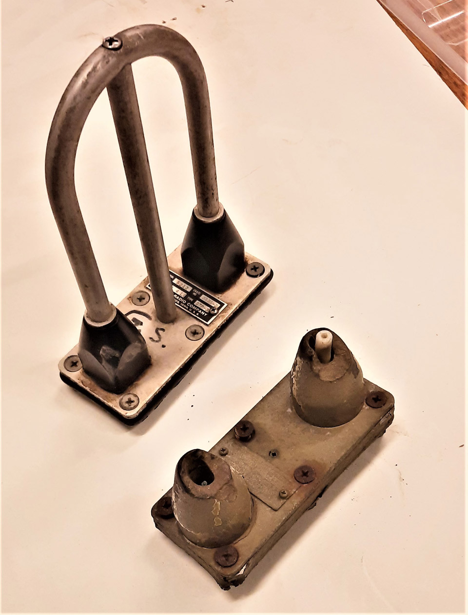
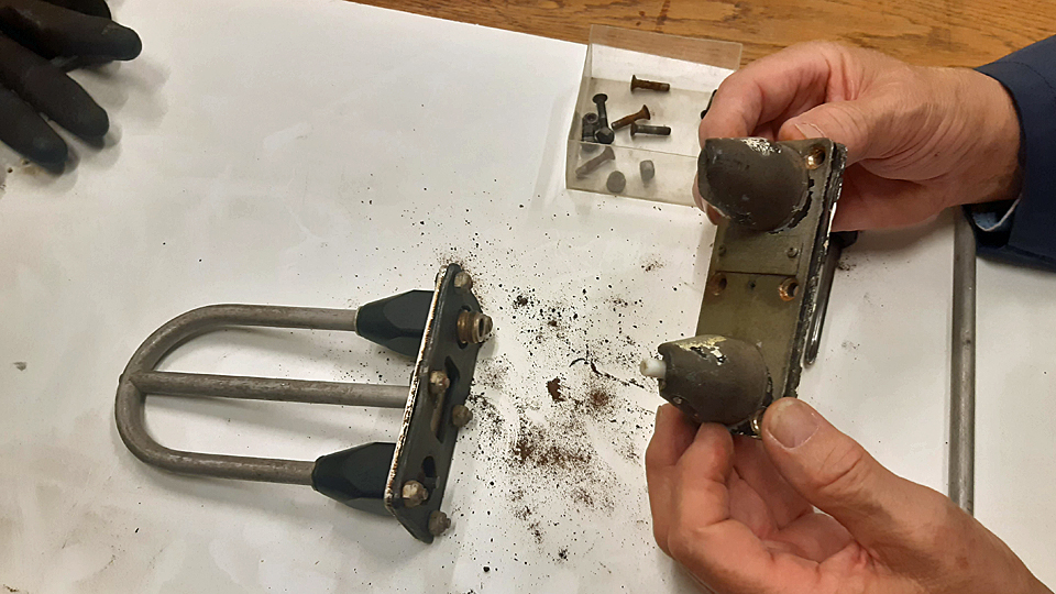
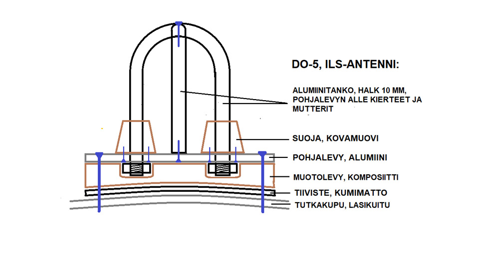
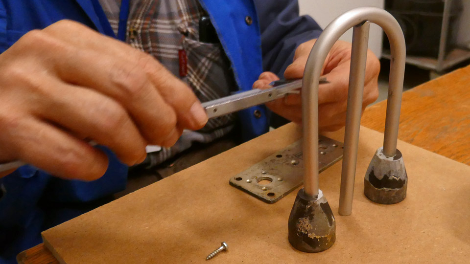
Making a look-alike ILS-antenna on the DO-5 noseSunnuntai 8.10.2023 - Tuesday Club member Last spring the missing lower part of the nose cone was made of glass fibre to the C-47 (DO-5), owned by Aviation Museum Society Finland. To make the nose appear real, it should include an Instrument Landing System glidepath antenna. It consists of the antenna arch, made of 10 mm thick aluminium tube, a vertical support in the middle of the arch, the antenna stem shields, a base plate, a wedgelike form plate and a rubber seal. With the aid of the form plate it’s possible to fasten the antenna tightly and at the right angle on the curved surface of the nose cone. Both ends of the antenna arch penetrate the stem shields, reaching the underside of the base plate, where at both ends of the antenna tube there’s a connector for the antenna’s electric wire.
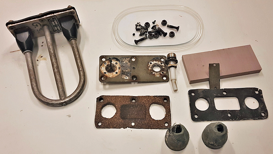
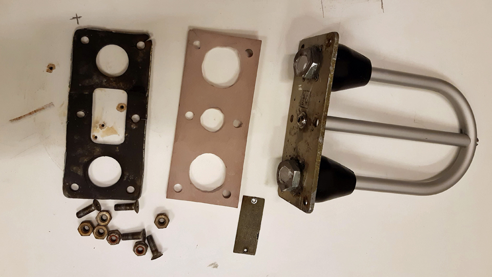
We don’t have this antenna to fit on the DO-5. So we decided to make a look-alike copy of the antenna, because the DO-5 will not be made airworthy. We were lucky to get an original antenna for making the look-alike copy, although it is without the form plate made of cork and the rubber seal belonging to the antenna. At the same time, however, we got a broken base of the antenna to be used as model, on which to make the look-alike copy. The base still had the form plate and the rubber seal in place. We are obliged to return the form plate, so it, too, has to be done.
Picture by Reijo Siirtola. To make a look-alike copy we made a model drawing, which is on the outside looks like the original antenna. The difference from the original antenna is that we replace the original antenna made of aluminium tube with a solid 10 mm thick aluminium bar. The fastening of the antenna arch to the base plate also differs. Because our antenna will not be functional, we’ll fasten the antenna arch to the base plate with nuts. For that purpose the ends of the antenna arch will be pushed with their shields 10 mm past the underside of the base plate and the ends will be threaded for the nuts. We’ll have to make a new form plate, too. We’ll make it out of mass plate that can be reshaped, instead of cork.
Photo by Reijo Siirtola.
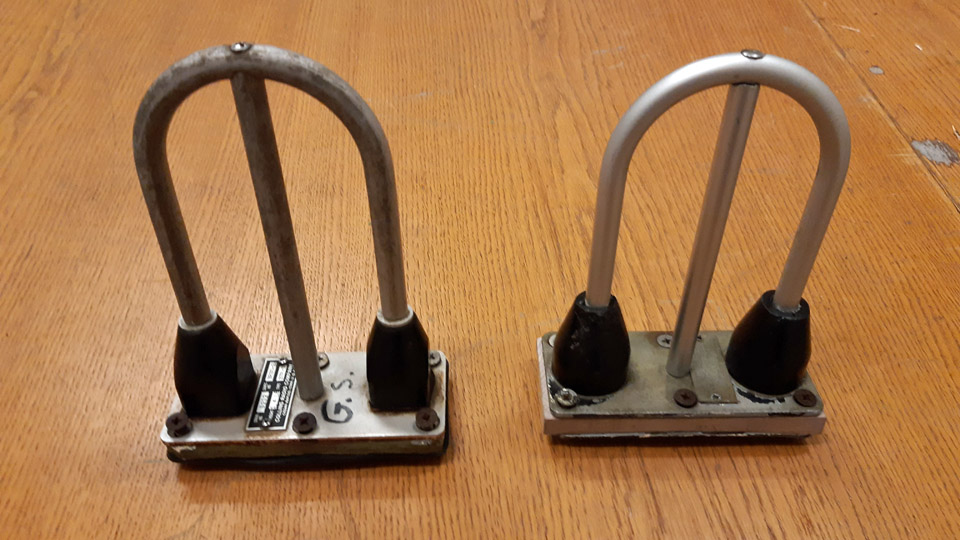
We started making the look-alike antenna by dismantling the antenna base we had. The antenna end shields, made of hard plastic, which were attached to the base plate with small screws, were broken. They were mended with epoxy putty. After the putty had dried, the shields were formed to their original shape and painted black. At the same time holes were opened through the shields, to enable the ends of the aluminium rods, modelling the antenna arch, to be pushed through the shields.
Photo by Juha Veijalainen.
To make the antenna arch, we cut an overlong piece of 10 mm thick round aluminium rod. To bend the antenna to its original form, we built a bending device. With it we bent the aluminium rod to the exact arched form of the original antenna. We pushed the overlong ends of the antenna arch through the antenna shields to cut them to exact length. For that purpose we measured from the original antenna the distance from the top of the arch to the surface of the base plate and added the necessary 10 mm, the distance that the antenna ends reached below the base plate. We cut off the extra bits from the antenna arch ends, after which the ends were threaded for the fastening nuts.
To make the vertical support in the middle of the antenna arch, we cut off from 10 mm aluminium rod an also overlong piece for the centre support. We shaped the top end of the rod as concave, for it to press tightly against the top of the antenna arch. We measured the necessary length for the centre support and marked the lower end of the rod accordingly and cut off the extra. The centre support is fastened at the top with a small bolt through the antenna arch and at the bottom end with a small bolt through the base plate.
Then we marked the attachment point for the centre support on the antenna arch and drilled a hole for the top fastening bolt. There’s already a hole in the original base plate for the bottom end bolt. After the holes have been drilled in the top and bottom ends of the vertical support, inside threads were made with a threaded pin, and the vertical support for the antenna arch was ready for fitting in.
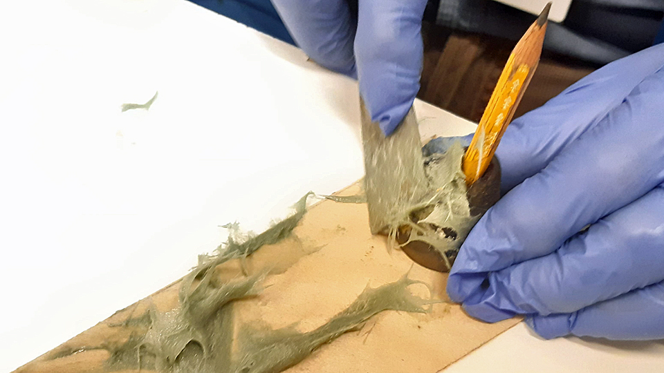
A new form plate to replace the original one made of cork had to be made. We made this form plate out of easily workable mass plate. The mass plate was ground wedgelike from the sides. The side against the base plate was left straight, but the side against the nose cone was worked as concave, according to the original model. Finally holes were drilled in the new form plate for the antenna arch nuts.
It was time to assemble the antenna. We pushed the ends of the antenna arch in their shields in such a manner that the vertical support in the middle of the arch settled nicely between the antenna arch and the base plate. We turned into place the bolts to the ends of the vertical support. Then we fastened the antenna shields to the base plate with four small screws through the base plate. That done we tightened the antenna arch into place with the nuts at the arch ends. The vertical support worked as a stiffener when fitting the antenna arch into place. When the form plate with its rubber seal was fitted, the glidepath antenna look-alike copy of the DO-5 instrument landing system (ILS) was finished. The next thing to do will be to go to Turku and install the antenna look-alike copy onto the upper edge of the DO-5 nose cone’s lower part made of glass fibre. The DO-5 is situated by the Turku Airport Terminal, beside the Caravelle “Bluebird”. We can measure the exact position of the antenna from the original “DAK” nose cone, so according to that we’ll drill the necessary holes into the upper edge of the lower half of the DO-5 nose cone made of glass fibre and install there the ILS-antenna look-alike copy we made. We’ll go and install the antenna still before the winter sets in. Photos by Lassi Karivalo except if otherwise mentioned. Translation by Matti Liuskallio. |
|
Avainsanat: aviation history, restoration, Tuesday Club, DC-3, C-47, DO-5 |
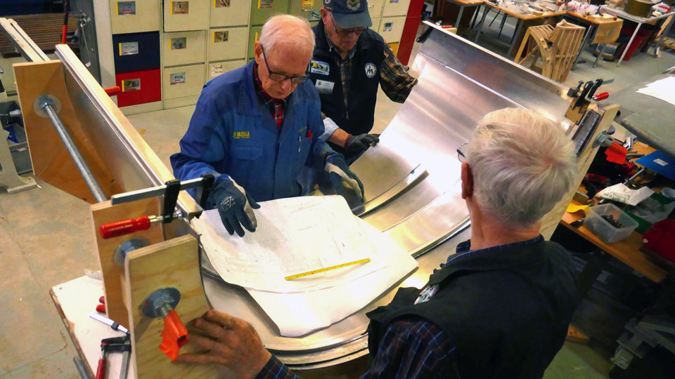
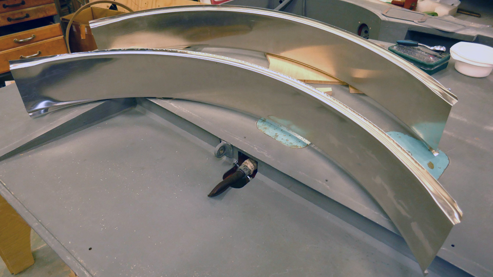
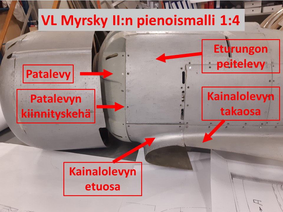
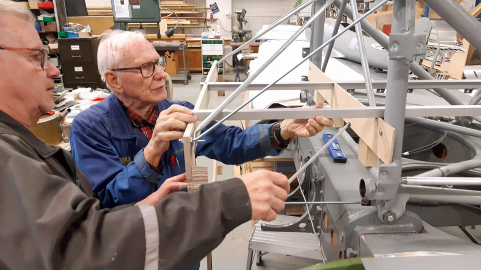
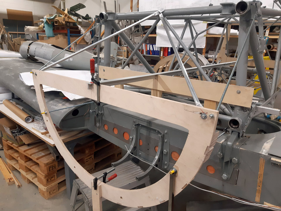
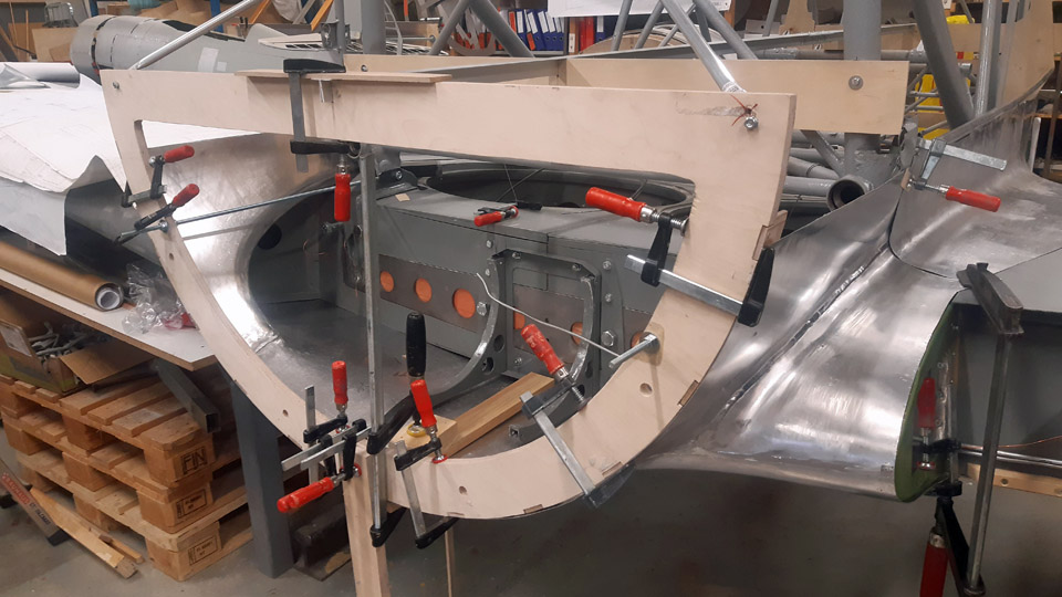
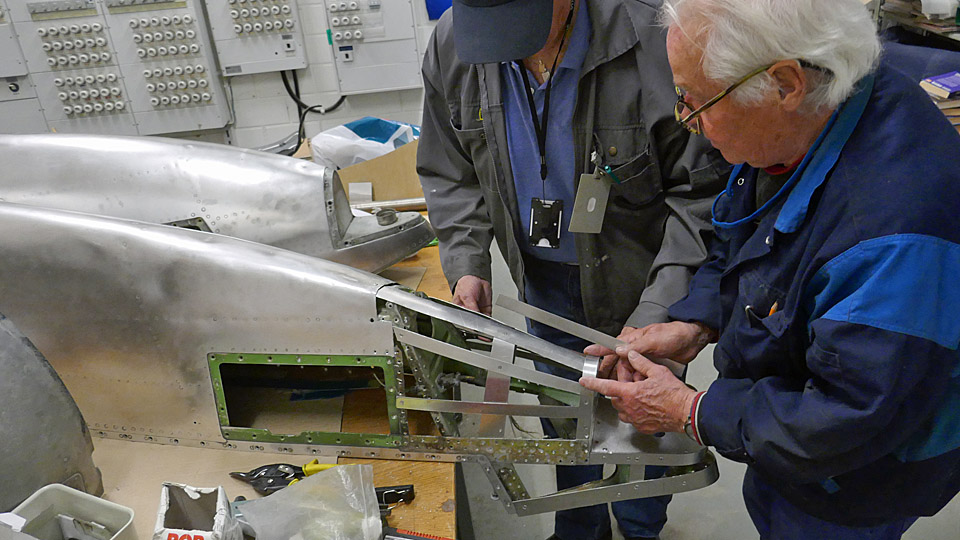
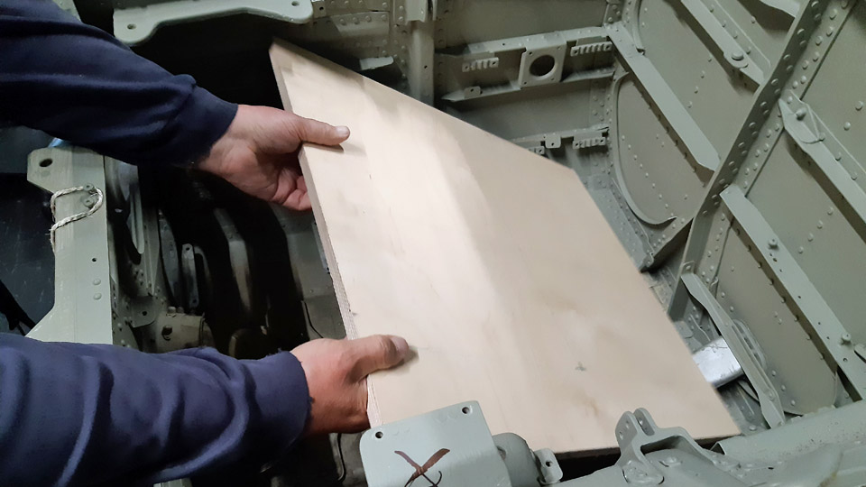
Fitting the front parts of the Myrsky wing root fairingsSunnuntai 1.10.2023 - Tuesday Club member The wing and fuselage seam is covered in the VL Myrsky II blueprints by sheets called the wing root fairings. The Myrsky wing root fairings are made of thin aluminium sheet. The Myrsky wing root fairing consists of two parts. The rear part covers the seam from the main spar to the trailing edge of the wing. The front part of the fairing in turn covers the area from the main spar over the leading edge of the wing to the lower surface of the wing and fuselage, reaching the main spar. The edges of the right-hand and left-hand wing root fairings meet under the fuselage in the centre line. The front parts of the wing root fairings are attached from their front edge to the tubular structure the heat shield’s fastening ring. To this same ring are also fastened the aluminium covering plates (engine cowlings) on the front fuselage, which can be opened. The fitting of the wing root fairing front parts, made during the restoration process of the Myrsky II MY-14), is underway at the Tuesday Club. This phase was made possible when the Myrsky MY-14 wing and the MY-5 fuselage frame were joined, to test the fitting of the wing to the fuselage frame. To fit the front ends of wing root fairings in place, we didn’t have the abovementioned fastening ring of the heat shield at our disposal. The MY-14 heat shield with its original fastening ring has already been assembled to the MY-14 fuselage under restoration at the Finnish Air Force Museum. We solved the problem of the lacking fastening ring by building a ring of sturdy plywood to the measurements of the original one. The plywood fastening ring we made must be assembled to the MY-5 fuselage frame we used for the test fitting of the wing, at exactly the spot corresponding the fastening ring of the heat shield. The reason for this is that the front parts of the wing root fairings could be fastened to the plywood ring the same way they will in their time be fastened to the actual heat shield fastening ring, which is presently at the Air Force Museum.
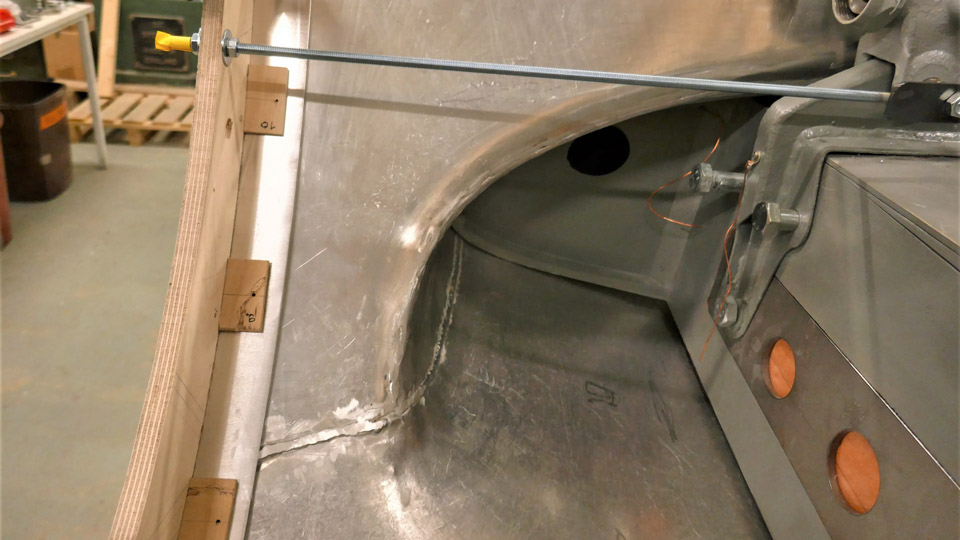
To measure the exact situation of the plywood fastening ring, which emulates the actual heat shield ring, we used the fuselage centre points marked in the Myrsky blueprints. The important one being point 51 of the fuselage centre, which is the centre point at the end of the transverse tube, located on the lower part of the front fuselage frame. From that point the three measuring points of the plywood ring were defined. They are the reference line in the fuselage centre line, formed by the metal tube, and the centre of the two bolts, which lock the wing to the fuselage frame.
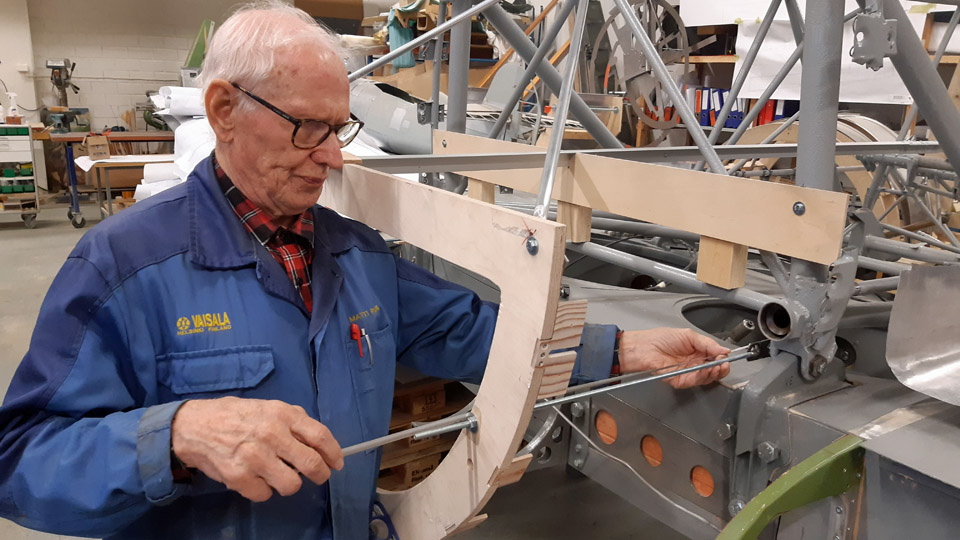
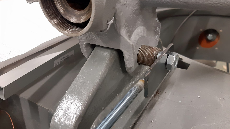
First the aluminium tube, which acts as the reference line was aligned to place. The top of the fastening ring was attached to the end of this tube. The plywood heat shield fastening ring was locked to the front bolts of the wing/fuselage joint with adjustable threaded rods from both sides. With the aid of these three fastening points the position of the plywood heat shield attachment ring could be defined to the millimetre in relation to the Myrsky fuselage frame. The top of the plywood attachment ring was propped to the fuselage frame with four metal supports, of which two are adjustable threaded rods. In addition the lower part of the attachment ring was propped to the floor.
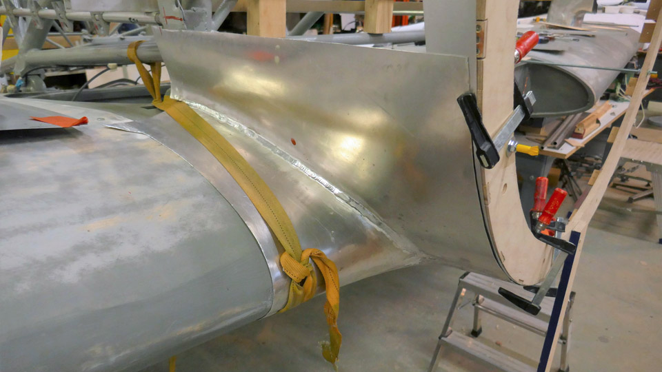
After the plywood ring was locked into place to the fuselage frame, the fitting of the front parts of the wing root fairings was started. The wing root fairing front parts were fitted to place in turns. They were attached first to the wing surface with cargo straps to keep the fairing tentatively in place during the fitting.
In the fitting, the wing root fairings were attached from their front part to the plywood attachment ring with clamps. It was noticed with pleasure that the aluminium sheet wing root fairings settled very well into place in relation with both the wing surface and the attachment ring. The front parts of the wing root fairings will finally be fastened to the fastening ring brackets with Dzuz-locks. In the test fitting of the wing root fairings the Dzuz-locks were replaced with plywood brackets, which were fastened to the plywood attachment ring. Because of the Dzuz-locks, a reinforcement ring will be made of aluminium sheet to the front edge of the wing root fairing. It has already been tentatively placed between the front part of the wing root fairing and the plywood brackets in the temporary fastening ring. Photos by Lassi Karivalo. Translation by Matti Liuskallio. |
|
Avainsanat: aviation history, restoration, MY-14, VL Myrsky, Tuesday Club |
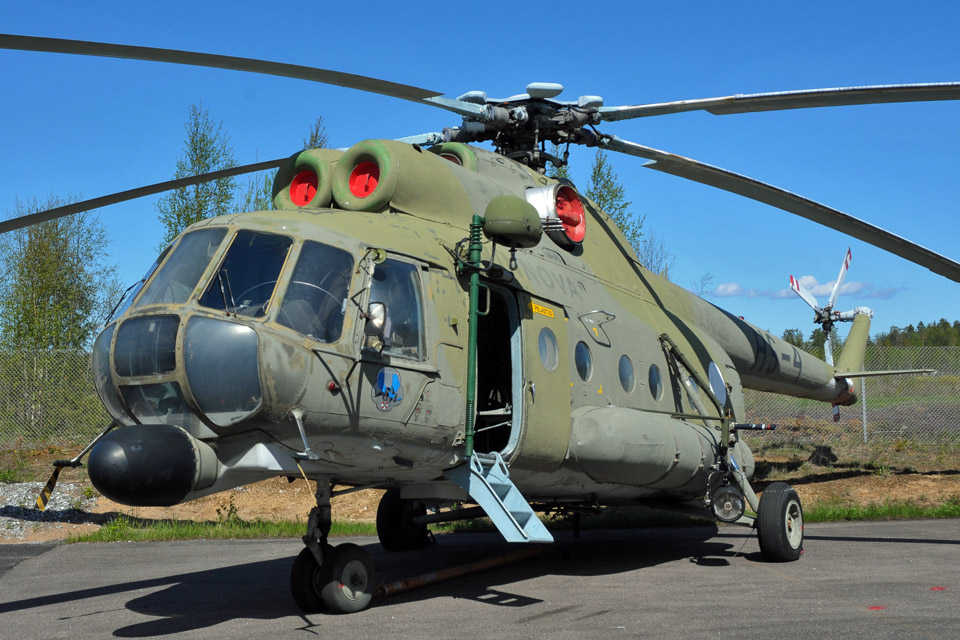
Mil MI-8T HS-4 tail boom stabilizer covering beganKeskiviikko 27.9.2023 - Tuesday Club member An example of a Mil MI-8T helicopter, used by the Defence Forces and registered as HS-4, is situated in the Karelian Aviation Museum. The tail boom stabilizers’ covering fabric is rotten and partly lacking altogether. Two thirds of the area of the stabilizers is covered with fabric and one third with sheets of aluminium. The aluminium surfaces are still in good condition, apart from a worn-out coat of paint.
Photo by Kimmo Marttinen In the spring the Karelian Aviation Museum offered the covering work of the stabilizers to Aviation Museum Society’s Tuesday Club. We agreed, because we had earlier covered the tail boom stabilizers of HS-6, which stands at the yard of the Tuulonen shopping centre. We promised to start the work in the autumn. For the covering a permission from The Finnish Defence Forces Logistics Command (FDFLOGCOM) was needed, because the helicopter is still in their possession. Permission was granted and in such a form, that we could cover the stabilizers with fabric as they originally were, or alternatively with thin aluminium sheet.
We agreed with the Karelian Aviation Museum that the stabilizers would be covered with a weatherwise better thin aluminium sheet, instead of fabric, as we had done with the HS-6 stabilizers last year. At the same time it was decided that after the covering the stabilizers would be painted all round, ergo the upper surfaces greyish green and the undersurfaces light grey, according to HS-4.
The Museum detached the HS-4 tail boom stabilizers in April, after which they were delivered to the Finnish Aviation Museum in Vantaa. At the beginning of the Tuesday Club’s autumn season the removal of the remaining rotten pieces of fabric was started. The last bits were removed with the tip of a knife. In the same manner we scratched off the thick layer of paint on the stabilizer’s steel reinforcements. Before the grinding of the HS-4 tail boom stabilizers’ faded and dirty aluminium surfaces could be started, the tone of the colour of the stabilizers’ upper and under surfaces was defined. At the Vantaa branch of Pintaväri the light greyish green of the upper surfaces was defined as the Defence Forces camouflage light green paint, code AN 22. With an electronic tone gauge the stabilizer’s faded green coat of paint was defined to be the greenish tone SG010-G9OY. The light grey of the undersurface was defined as S2500-N. We also defined the tones of the stabilizers’ aluminium surface, using the colour maps at the Finnish Aviation Museum. According to them the upper surface green was RAL 6013 Reed Gray. The undersurface light grey is closest to RAL Effect 830-1. According to the camouflage scheme of the Defence Forces for Mi-8 helicopters, the tone of the stabilizer upper surface is Light bronze green, and the undersurface is Light aircraft gray. We’ll take a closer look at this tone-of-paint-puzzle before the actual painting phase of the stabilizers.
The grinding of the faded paint surfaces was done by a random orbital grinding machine, using P180 and P240 grit sanding discs. Our aim wasn’t to grind the faded coats of paint to pure aluminium. It’s sufficient when dirt and loose paint have been removed from the surfaces and the stabilizer steel reinforcements cleaned of rust. When grinding the stabilizer surfaces, darker green adhesive primer appeared. On some uneven parts pure aluminium surface appeared.
There are roundhead rivets on the stabilizer and the stabilizer’s tip, made of glass-fibre reinforced plastic, has been attached with roundhead screws with grooves. When working on the rows of rivets and screws, the random orbital grinding machine wasn’t the best tool. So we used a grinding brush fixed to a power drilling machine to clean the rivet and screw stubs, which was very suitable for the purpose. Both the HS-4 tail boom stabilizers are ready now for the actual covering. Photos by Lassi Karivalo except if otherwise mentioned. Translation by Matti Liuskallio. |
|
Avainsanat: aviation history, restoration, Mil Mi-8, HS-4, Tuesday Club |
Covering the DO-5 openings for the stabilizersTorstai 21.9.2023 - Tuesday Club member When in June we were preparing the C-47 (DO-5) fuselage, owned by Aviation Museum Society Finland, for display at the Turku Airshow, the working list included covering the DO-5 tail openings for the stabilizers with aluminium plates. The reason for the covering being to prevent rainwater from getting inside the fuselage. At the time we didn’t have time to make the covers to shield the openings. At the beginning of the Tuesday Club’s autumn season we included the covering of the stabilizer openings on our work list.
Photo by Janne Salonen. At the moment, the DO-5 fuselage is situated by the Turku Airport, next to the Caravelle III or OH-LEA “Bluebird, which is the object of restoration and owned by Aviation Museum Society Finland. That’s why we had to go to Turku to measure the covers for the stabilizer openings. On Monday, September 4th, we headed for Turku.
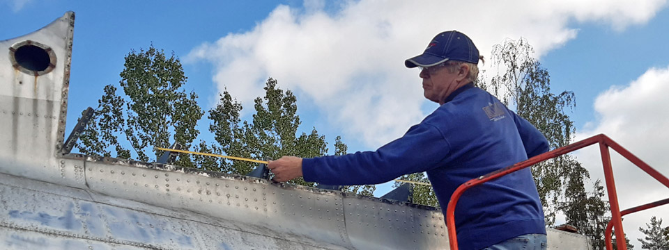
Photo by Jouko Tarponen. Measuring the sizes of the openings on the DO-5 and making cardboard templates of them took quite a few hours. Our work was facilitated by the fact that we had at our disposal a high enough worktop, given to us by the Caravelle restoration project, on which we could reach to measure the vertical stabilizer’s opening, which was highest up. Or as a matter of fact, the vertical stabilizer’s attachment point isn’t an opening at all, like the horizontal stabilizers’, but the vertical stabilizer is attached from its lower part to aluminium attachment brackets rising from the fuselage.
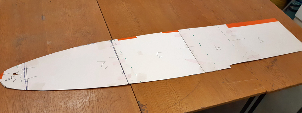
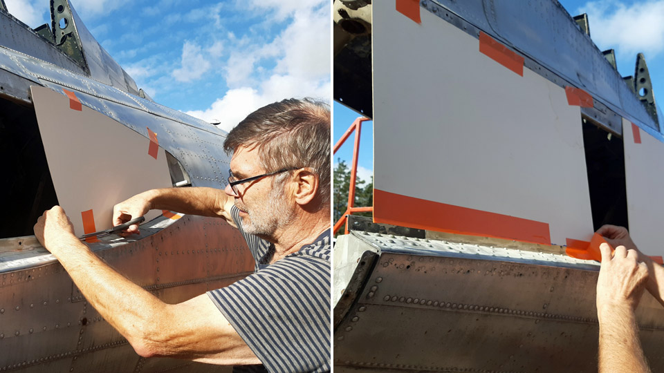
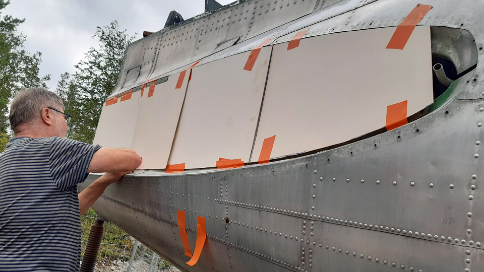
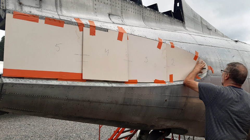
We started with the right-hand side horizontal stabilizer opening in the tail. A cardboard template was made by shaping and attaching to the stabilizer opening several numbered cardboard panels, one after the other. Finally we shaped a cardboard template of the curved leading edge of the stabilizer opening. Because we assume that the right- and left-hand side openings are symmetrical, we only made a cardboard template of the right-hand side stabilizer opening.
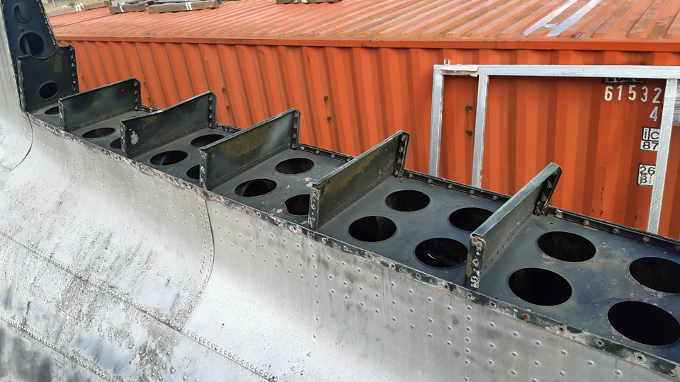
A cardboard template of the vertical stabilizer’s attachment point wasn’t made, because it isn’t an opening in the fuselage like those of the horizontal stabilizers. At the vertical stabilizer’s attachment point, from the top of the “cut off” tail, seven rectangular 10 cm high solid attachment brackets, made of aluminium, are sticking up stretching 240 cm in distance. The vertical stabilizer is attached to these brackets with screws, and from its hem to the side of the fuselage.
Photo by Reijo Siirtola. We ended up sheltering the vertical stabilizer’s attachment point with a rainproof case. The case would be pressed on the 10 cm high attachment brackets. The top of the case would be of sturdy plywood, covered with a sheet of aluminium. The sides of the case will be made of sheets of aluminium. They will be attached from their top rim to the edge of the plywood cover, so that the top rim remains under the downward bent edge of the aluminium sheet on top of the case. This will guarantee that the joint becomes watertight. The bottom sides of the case overlap the top of the fuselage by 4 cm. Thus the rainwater running along the case’s sides can’t get inside the fuselage.
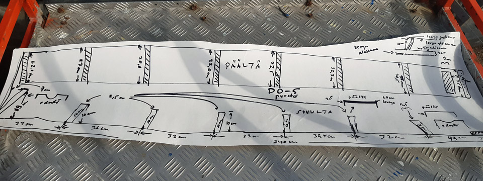
To build the case covering the attachment point of the vertical stabilizer, a sketch was made, where all the relevant details to build the case were measured.
Photos by Ismo Matinlauri.
Because the DO-5 tail cone isn’t fixed to the fuselage, the tail cone opening must also be protected from the rain. The opening will be protected with two aluminium sheets, because of the structure of the tail’s cross-section. So we made individual cardboard templates of the top-and lower halves of the fuselage of the DO-5 without the tail cone.
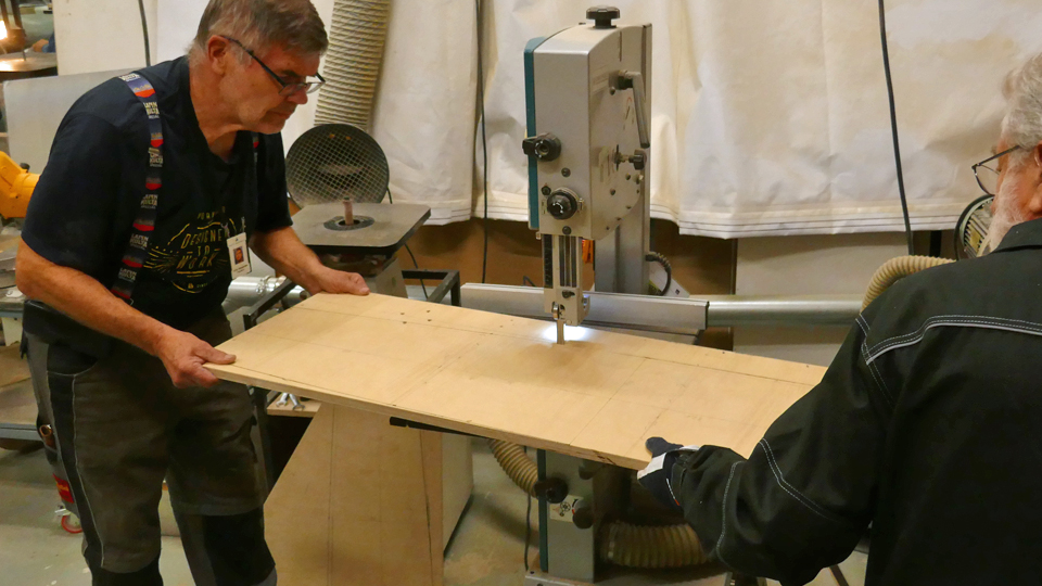
The covering of the DO-5 tail stabilizer openings was started with the case protecting the vertical stabilizer. First the plywood top will be built. It will act as the frame for the case. There was suitable, sturdy plywood in the material storage of the Finnish Aviation Museum. We will have to make the top plate out of two halves, though, because the length of the plate at our disposal isn’t enough to cover the whole 240 cm length. The measures for the vertical stabilizer taken in Turku, were transposed to the plywood plate, which became the case’s top. Next the top plate will be sawn into measure. Photos by Lassi Karivalo except if otherwise mentioned. Translation by Matti Liuskallio. |
|
Avainsanat: aviation history, restoration, Tuesday Club, C-47, DC-3, DO-5 |
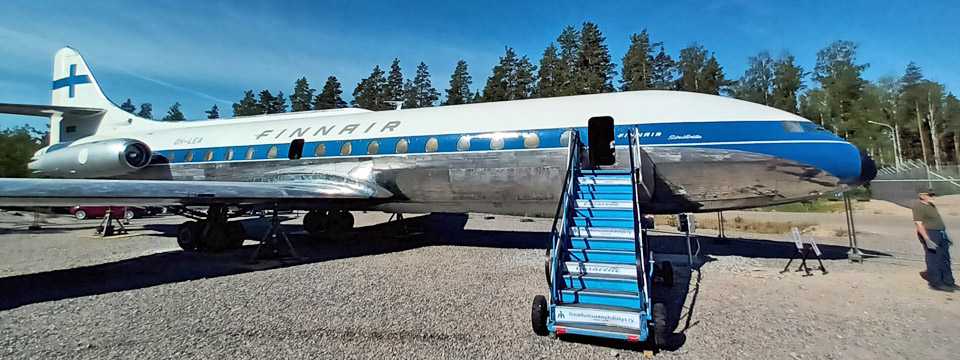
Caravelle's autumn season started in the beginning of SeptemberKeskiviikko 6.9.2023 - Ismo Matinlauri The restoration work of the Caravelle OH-LEA at Turku airport started efficiently on Monday, September 4th, when there were nine volunteers at work. In the Turku area it rained a lot in August, and it wasn’t possible to do any of the remaining restoration work outside the aircraft. During the summer weekends the Caravelle was open to visitors, and this led to some restrictions to starting the work inside the aircraft.
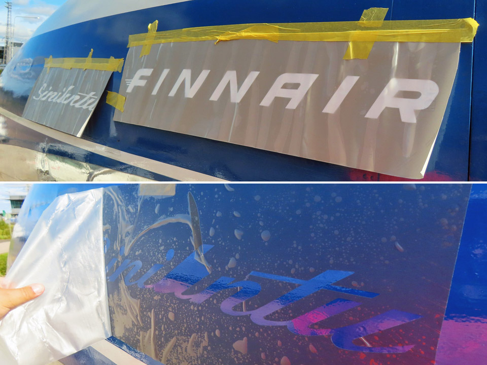
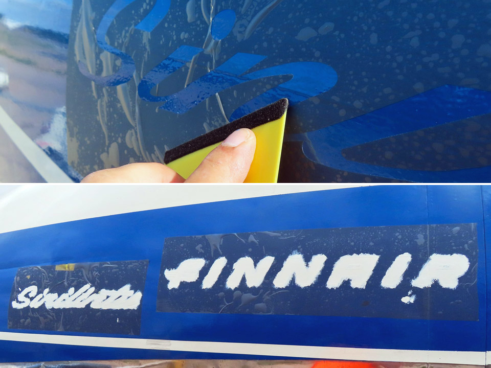
On the last weekend we had the summer season’s last open doors event and after this it was possible to continue the restoration work from where we had left it in June. The half cloudy weather was ideal for sanding, polishing, and painting the last identification markings.
On the underside of the fuselage there is a small area which needs to be sanded and painted with aluminium colour paint. The last identification markings will be painted on the wings and fuselage. The largest of these is the registration OH-LEA missing on the underside of the wing.
Photos by Lassi Karivalo. A lot of polishing work is still needed, this is the main item to be completed on the outer surface. Polishing will be continued as long as the weather allows. However, there is so much to be polished that the work will continue next spring.
The work inside the aircraft has also started. The repairs and painting of the flight deck and the toilet area will be the first work items. The floor and the ceiling area in the cabin will follow in the coming weeks.
It was a pleasure to have visitors from the Tuesday Club at Vantaa. Three club members came to Turku to measure the openings on the tail of the DO-5, which is temporarily parked next to the Caravelle. Protecting covers will be made at the Tuesday Club to cover the holes before the autumn storms arrive.
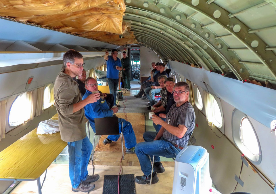
The busy afternoon was spent at work, but there was a moment for lively discussion when the Turku team and the Tuesday Club members had a coffee break together inside the aircraft at “Café Caravelle”. The Tuesday Club is a valuable support and aid for the Turku team when the details of the restoration work are pondered. We are looking forward to making good progress during the autumn. Photos by Jouko Tarponen except if otherwise mentioned. Translation by Erja Reinikainen. |
|
Avainsanat: aviation history, restoration, Caravelle, OH-LEA, Sinilintu, Bluebird, Tuesday Club |
Tuesday Club's autumn season 2023 under wayKeskiviikko 30.8.2023 - Tuesday Club member Tuesday Club members returned from their summer break “back to the lathe” on August 22nd. However, once again it must be noticed that the group working on the VL Myrsky II (MY-14) had the stamina to work with the Myrsky through the summer. As a result of their effort the Myrsky wing is now united with the MY-5 fuselage frame, which we have as a testing fuselage. Thanks to this the wing/fuselage joint covering fairings could be test-fitted.
Along with the Myrsky restoration project, the main project of autumn 2023 is to continue the restoration of Valmet Tuuli III (TL-1), which has been on hold for a number of years. In this project, led by the Finnish Aviation Museum, we’ll be concentrating on the aircraft’s fuselage, whose outer exterior surface we had started to polish clean and shiny already in the autumn season of 2022.
In 2015 and 2016 nearly all parts of the Tuuli II had been dismantled for restoration purposes, including the cockpit instruments and gadgets. For the most part they had also been cleaned. In 2018 these parts were packed in case the Finnish Aviation Museum would have moved at that time to a cargo terminal freed by Finnair. However, that didn’t happen and now we continue in a way from where we were left then.
First we’ll concentrate on the thorough cleaning of the Tuuli cockpit, which was nearly emptied. The cockpit’s inner surfaces and structures will be washed clean, possibly partly with a pressure washer. Simultaneously we’ll start to go through the parts packed in 2018 and cleaning them where cleaning will be necessary. The long-term aim of our work is to assemble the Tuuli for display. It will, however, take a few years before that will happen.
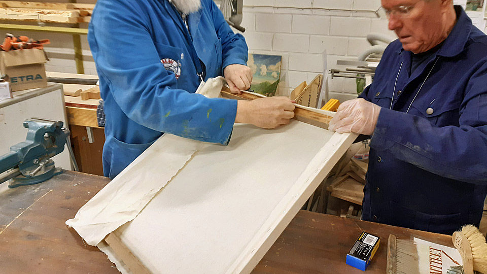
The horizontal stabilizer of the 1920’s Caudron C.59 advanced trainer was refurbished and was fully ready to be covered with fabric already a couple of years ago. Now we’ll start to cover the stabilizer with cotton fabric. However, first we’ll test its tightening properties. For that reason we built a wooden frame, onto which we attached a piece of the acquired fabric. We already made a water tightening test on the fabric by spraying it with water. We will test with lacquer by starting with thinned nitro cellulose lacquer ending up with pure lacquer. The patched lower wings of the Caudron took too much space, so they were moved from the restoration workshop to the I-hall of the Finnish Aviation Museum, to wait for the next work phase.
Photo by Janne Salonen. We will carry on with work on the C-47 (DO-5) fuselage, Caravelle III (OH-LEA “Bluebird”) and MiG 21 BIS (MG-111) cockpit. Aviation Museum Society’s owned DO-5 and OH-LEA are presently on show in the vicinity of the Turku Airport Terminal, but the cockpit of the MG-111, which will be turned into a cockpit simulator, is at the Finnish Aviation Museum. On top of that, we ‘ll cover the derelict tail boom stabilizers of the Mil Mi-8 (HS-4), situated at the Karelian Aviation Museum.
Of the jobs assigned to the Tuesday Club to refurbish the Caravelle, the repairing of the right-hand wing tip, including the making of the navigation light frames, is still unfinished. There’s also been talk about refurbishing the pilots’ seats into functioning condition at the Tuesday Club. This would necessitate bringing the seats from Turku to Vantaa. Also the making of protective sheaths of fabric or leather for the pitot tubes beneath the nose would be on offer for us.
Photo by Ismo Matinlauri.
During the spring season we worked hard to get the C-47 (DO-5) fuselage, which had been used for training paratroopers for the Defence Forces, ready to be on show at the Turku airshow. Time ran out for us then to do all we planned, and we are going to catch up now with the work, even though the fuselage is in Turku. The most important item on the list will be the making of protective covers for the openings for the horizontal-and vertical stabilizers, to prevent rain water getting into the fuselage. The stabilizers naturally aren’t attached to the fuselage now. We are also making a lookalike copy of the glide path antenna, which is a part of the ILS (instrument landing system) in the nose of the DO-5. For that we have an original antenna as a model and the stem of a broken antenna.
During last year’s autumn season and the spring season we managed empty the MiG 21 BIS cockpit for it to be transformed into a MiG 21 BIS cockpit simulator. This cockpit section was received by Aviation Museum Society when the aircraft was scrapped by Photos by Lassi Karivalo except if otherwise mentioned. Translation by Matti Liuskallio. |
|
Avainsanat: aviation history, restoration, Tuesday Club |
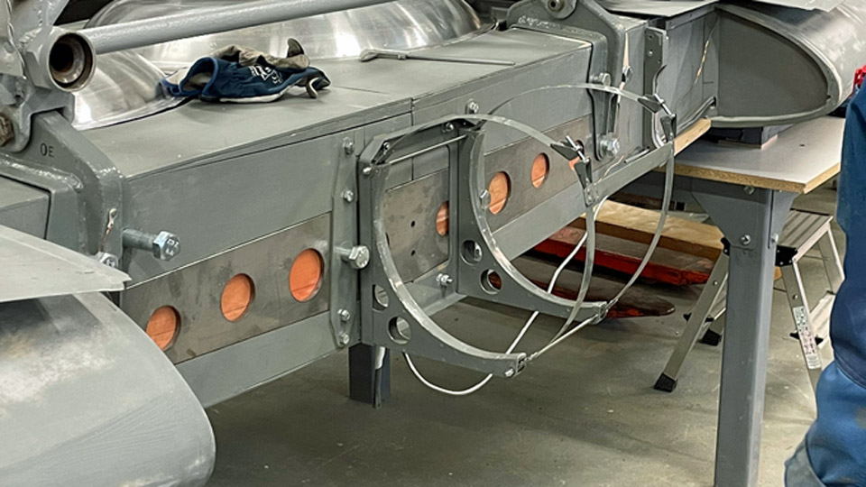
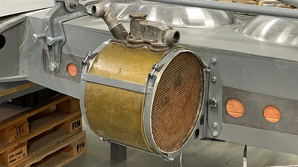
Time to test-fit the Myrsky oil coolerLauantai 19.8.2023 - Tuesday Club member Parallel with the fitting of the wing root fairings, the test-fitting of the barrel-shaped oil cooler was commenced. The Myrsky oil cooler is situated in the fuselage centre line, attached to the main spar “forehead”. Air comes to the oil cooler through an air duct from the left-hand wing’s leading edge. Respectively, after going through the oil cooler the air exits from the underside of the right-hand wing. For the MY-14 fighter restoration we have at our disposal an original Pratt & Whitney R-1830 Twin Wasp engine’s oil cooler, the very engine that powered the Myrsky. We received it from Airveteran Oy. Instead we have had to manufacture all the accessories for the oil cooler, including the ducts for the supply and exhaust air and the dampers adjusting airflow. The air ducts were made of 1mm thick, easily workable aluminium sheet. The pieces cut off the sheet were shaped in wooden shaping lasts, after which the seams were welded. We also made the dampers or gills that adjust the amount of air going through the oil cooler. The dampers adjusting the amount of supply air are controlled mechanically from the cockpit.
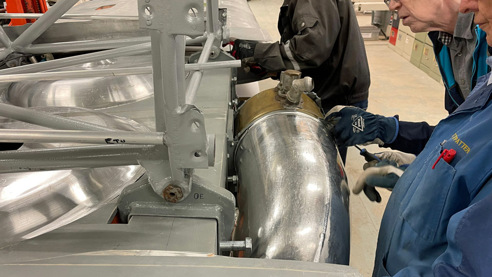
Photos by Heikki Kaakinen. Normally the oil cooler is permanently attached to the main spar. Because the MY-14 wing is made of two halves and the oil cooler is situated at the junction, the oil cooler must always come off, when and if the Myrsky will be dismantled for transportation to another museum or some other place to be placed on display. That’s why a handy rack with attachment straps was constructed. The oil cooler will be strapped on it and the rack is easily detachable from the wing spar and can also easily be reattached.
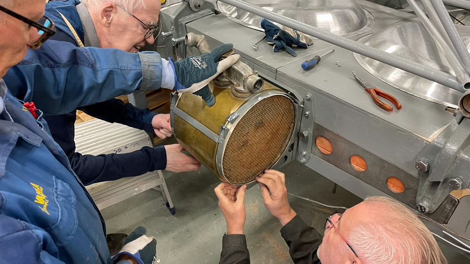
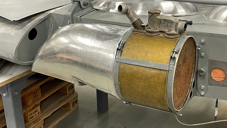
Photos by Heikki Kaakinen The test-fitting of the oil cooler was started by attaching the oil cooler attachment rack on the junction of the wing halves. The oil cooler was tightened to the straps. After that the cooler’s right-hand cooling air exhaust duct was fitted into place. The duct opens to the underside of the right-hand wing’s leading edge.
Photo by Heikki Kaakinen
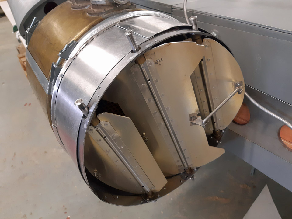
The gills adjusting the incoming airflow were attached to the other end of the oil cooler. The gills are situated between the oil cooler and the supply air duct. The duct for incoming air is twofold. One end of the duct’s straight part is attached to the supply air damper and the other end to the front end of the L-shaped supply air duct. The opening of the incoming air duct is situated in the right-hand wing’s leading edge. There’s still work to do in fitting the oil cooler parts before every part is settled in its place as planned. A veritable “collection of gadgets” this Myrsky oil cooler system has proved to be.
The pitot-tube, which measures the airspeed of the aircraft and is situated on the left-hand wing, was also test-fitted. The pitot-tube rack has been in place for long in the left-hand wing’s leading edge. We noticed, to our chagrin, that the 300 mm pitot-tube at our disposal was of a wrong length. It should be of the 500 mm long type. This can be seen in the Myrsky blueprints and photos taken of the Myrsky. Might there be a pitot-tube of the right length for us in the collections of the Finnish Air Force Museum?
Along with all other tasks numerous inspection hatches on the wings are being fitted into place. We had to grind the collars of the hatches a bit deeper, so that the hatches would become flush with the wing surface. Photos by Lassi Karivalo except if otherwise mentioned. Translation by Matti Liuskallio. |
|
Avainsanat: aviation history, restoration, MY-14, VL Myrsky, Tuesday Club |
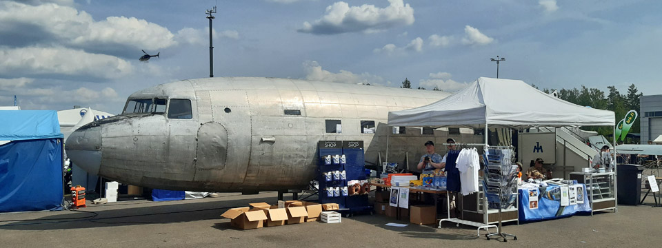
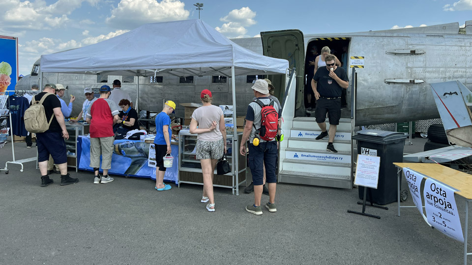
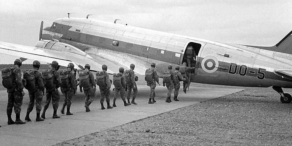
The DO-5 fuselage on display at the Turku AirshowPerjantai 23.6.2023 - Tuesday Club member The fuselage of the Douglas C-47 A, registered DO-5, owned by Aviation Museum Society Finland was on display at the Turku Airshow as part the Aviation Museum’s stand. The DO-5 fuselage, which was used by the Finnish Air Force for training paratroopers in the 1960’s, was refurbished enough in the Aviation Museum Society’s Tuesday Club for the fuselage to be brought on display to Turku. The Airshow visitors could be allowed inside the fuselage to see how the aircraft was used in training the paratroopers.
Photos by Janne Salonen
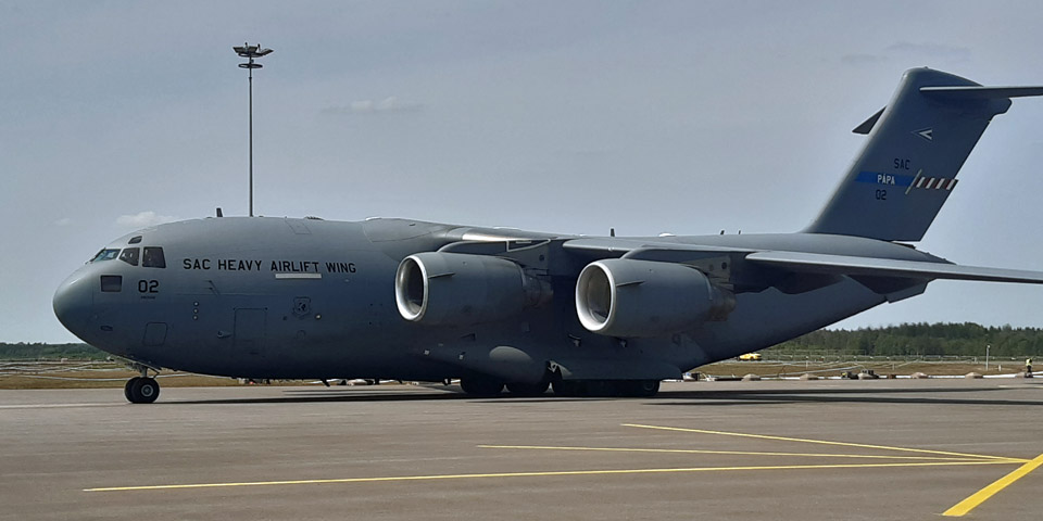
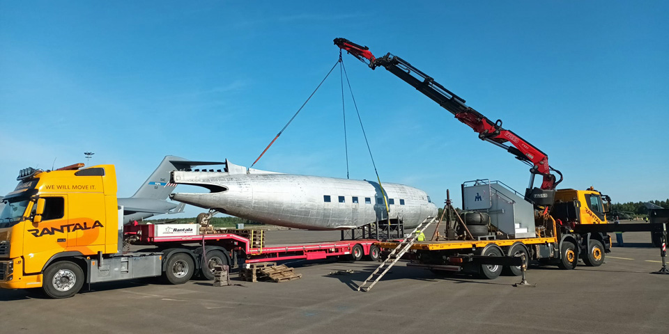
Photo my Lassi Karivalo The DO-5 fuselage was transported from the Aviation Museum’s yard at Vantaa to Turku Airport on the Thursday before the Airshow weekend. The Aviation Museum Society’s stand was situated in the Airshow area close to the mighty Boeing C-17 Globemaster. So there they were in close vicinity, the USA Air Force Air Transport aircraft from the 1930’s and the 1990’s, albeit in different calibre.
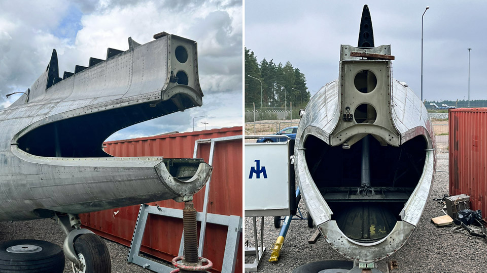
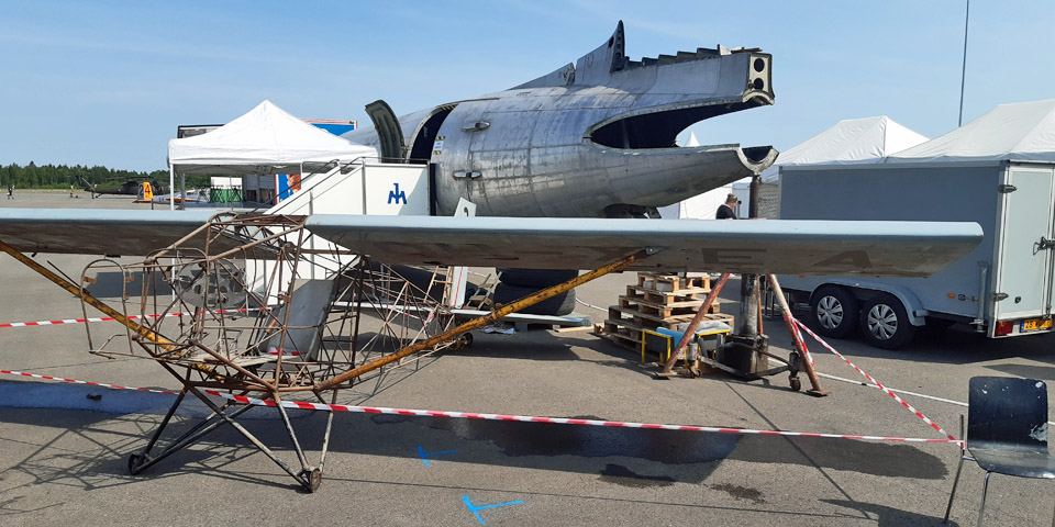
Photos by Lassi Karivalo The Society had also brought on display the “Snoopy” aircraft donated to the Society and awaiting full restoration. This experimental aircraft from 1969 was constructed by the brothers Ari and Esko Hietanen from Turku.
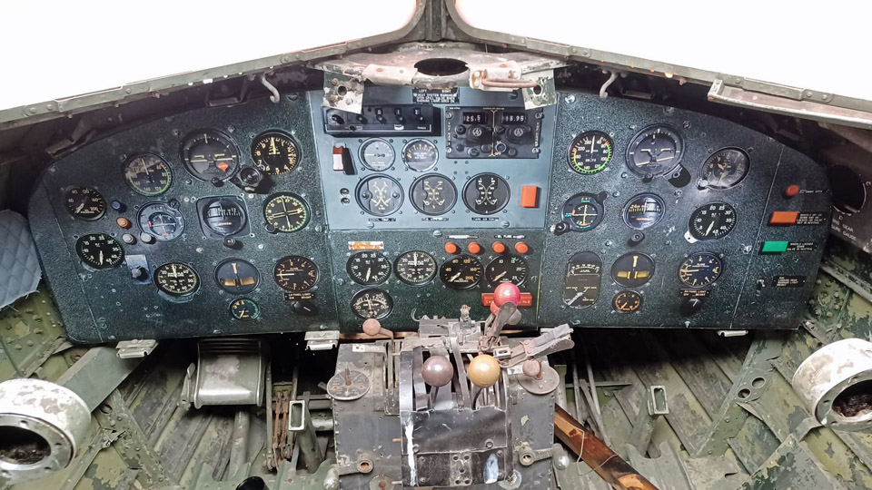
Photo by Janne Pauni The DO-5 fuselage drew great interest among the Airshow visitors. On both show days, Saturday and Sunday, people poured into the DO-5 to hear about the history of this individual aircraft and about the refurbishing projects done by the Tuesday Club, including the full-sized photo in the cockpit of the instrument panel of the Kar-Air DC-3 OH-VKB, which is situated in the Aviation Museum.
Photo by Juha Veijalainen
Photo via Jarmo Kaipainen We told the visitors in particular how the DO-5 was used at Utti as a jump aircraft to train paratroopers and after it was taken off from flying, how the fuselage was utilized on the ground as a dry run platform before the first real jump as a paratrooper. We didn’t keep count how many persons visited the interior of the DO-5, but we estimate that the number is nearer 2000 than one thousand. It was a pleasant incident, when someone visited the aircraft and said that he had jumped from this very aircraft in 1963 on his conscript time, when it still served as a jump aircraft. Those who visited the aircraft were also very interested in the Aviation Museum Society’s DO-5 project in itself. They thought it was commendable that Aviation Museum Society Finland saved from the scrap yard an aircraft used by the Air Force in the 1960’s, with the cabin still in its original paratrooper training attire. Our project isn’t solely to preserve a C-47 because there are plenty of them still flying in the world, including converted airliner flying “Dak”, the OH-LCH, owned by Airveteran Oy. In preserving the DO-5 we’ll be able to save for the future generations Air Force history from the 1960’s concerning paratrooper training. We at the Tuesday Club can be proud as Punch for what we have already done to refurbish the fuselage. Without our input the fuselage wouldn’t have been in such a condition that it could have been put on display. There’s still a lot to do with the DO-5, but time will show how far we can go. The positive feedback we received at the Turku Airshow only confirmed how important our idea was, from the point of aviation history, to save the DO-5 used by the Air Force in training paratroopers more than 50 years ago. We, inside the DO-5 telling the visitors about the history and use of the aircraft, were literally in a hot spot. The scorching weather and the sun blaring from a cloudless sky heated the interior really hot. The temperature must have been nearly +50 degrees Celsius, even though we had installed a few fans to ease our existence. We did survive the hours’ long “sauna” of both airshow days. It must be admitted that cases of mineral water and Coke relieved the situation in preventing dehydration. The positive attitude of the visitors motivates Aviation Museum Society Finland to carry on with the refurbishing of the DO-5. From the point of view of the Tuesday Club the situation is problematic, because for the time being the DO-5 remains in Turku and our club operates in the Finnish Aviation Museum’s premises in Vantaa in co-operation with the Museum.
Photos by Janne Salonen After the Airshow the DO-5 fuselage was transported to Turku Airport to the vicinity of the Caravelle III, which was restored as Finnair’s “Bluebird”, and is owned by Aviation Museum Society Finland. There the Old Lady DO-5 can stay by the little younger Old Lady the “Bluebird” on public display.
Photos by Janne Salonen The former SAS Caravelle (SE-DAF) presently in Finnair colours, outside the actual Airshow area also interested the Airshow visitors very much. So about 1300 people popped in to get acquainted with the Caravelle “Bluebird” on their way from the Airport terminal bus-stop to the gates of the Airshow area. It was well worth getting acquainted with, because the newly painted Finnair “Bluebird is a truly resplendent sight. Translation by Matti Liuskallio. |
|
Avainsanat: aviation history, restoration, Tuesday Club, C-47, DC-3, DO-5 |
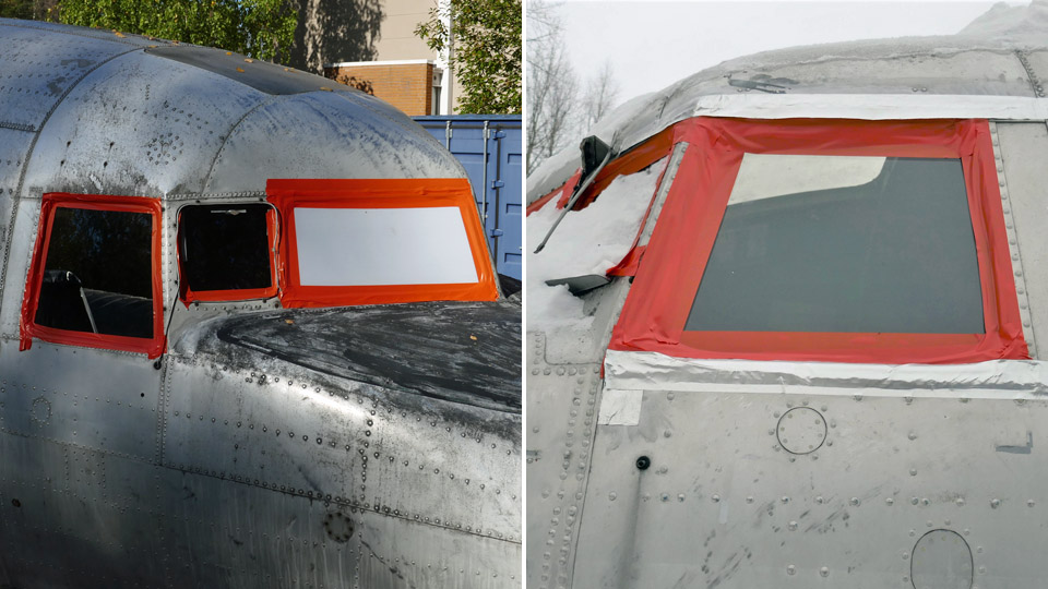
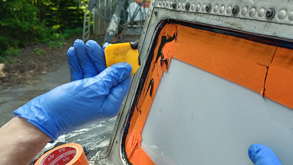
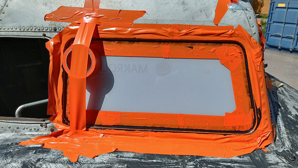
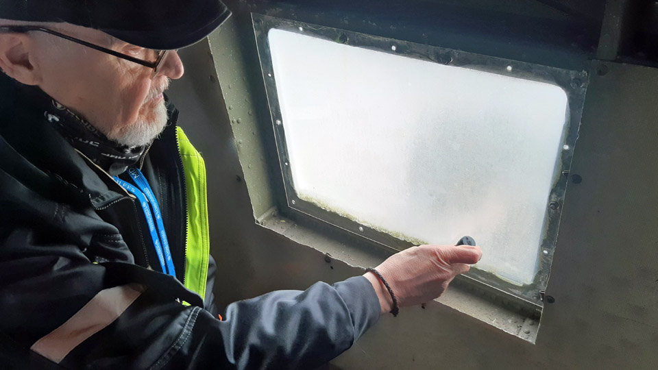
Tuesday Club's DO-5 work completedKeskiviikko 21.6.2023 - Tuesday Club member The hard work of the Tuesday Club members was instrumental in getting the fuselage of the type C-47A DO-5, owned by Aviation Museum Society Finland, into sufficient shape for putting it ready for showing before the Turku Airshow. It was touch and go because the last tasks weren’t finished until two days before the fuselage of DO-5 was transported from the yard of the Finnish Aviation Museum to Turku Airport on June 15th, 2023. The last significant project was to install new plexiglass panes for the cockpit. The Air Force DO-5 hasn’t had original panes in the cockpit for decades. Part of the windows lacked panes altogether, resulting rainwater and snowstorms ruining the cockpit badly, whilst the fuselage lay forgotten for decades in the Utti forests. Because the original cockpit panes and the large sliding panes on both sides of the cockpit weren’t available, we ended up with acquiring plexiglass panes for the window openings. On top of that we decided to attach the plexiglass panes to their frames with a mixture of glue and sealant mass. In this way the windows become watertight, preventing water to seep into the fuselage. This also meant that the big sliding panes on both sides of the DO-5 cockpit couldn’t be slid open anymore.
To acquire new 5mm polycarbonate plexiglass panes we made a template out of thin plywood for each of the window openings. For the windscreens we had already in the autumn acquired from ETRA plexiglass panes ready cut to form. Cold weather and the oncoming winter, however, put paid to carrying on with the installing of the windowpanes. We fastened then the plexiglass panes and the temporary panes in the other windows with plastic tape from their edges to wait for the warmer temperatures of the spring, when we could continue with the cockpit windows.
Photos by Lauri Veijalainen
Other tasks to refurbish the DO-5 fuselage in the spring delayed attaching the new plexiglass panes, so that we didn’t get to it until May 2023. Then the plexiglass panes for the large sliding windows on the sides of the cockpit were acquired.
Photos by Lauri Veijalainen
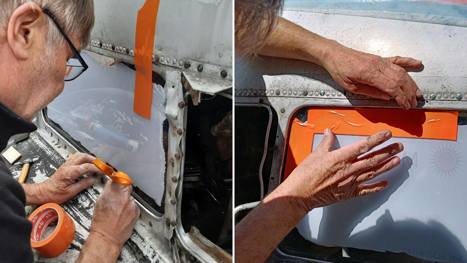
Each plexiglass pane was squeezed into its frame and a thin rubber strip was installed under the lower edge of the pane in order to get the pane at the right elevation in its groove. After that the edges of the panes were taped either by masking tape or with plastic tape so that there remained a suitable zone for the glue and sealant mass. The tape is to protect the rest of the surface of the pane from the sealant mass to spread and that the seam of the sealant mass will be clean.
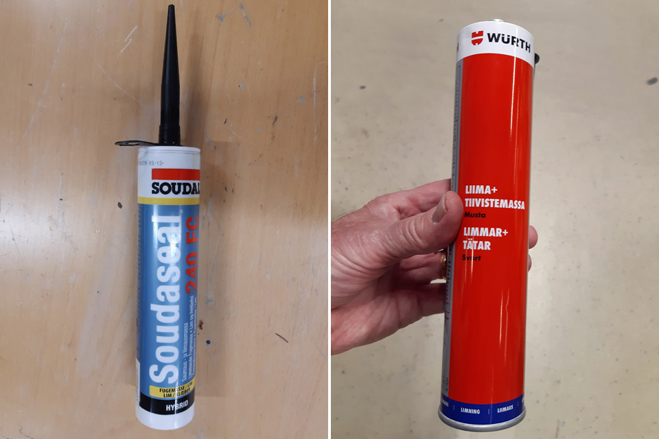
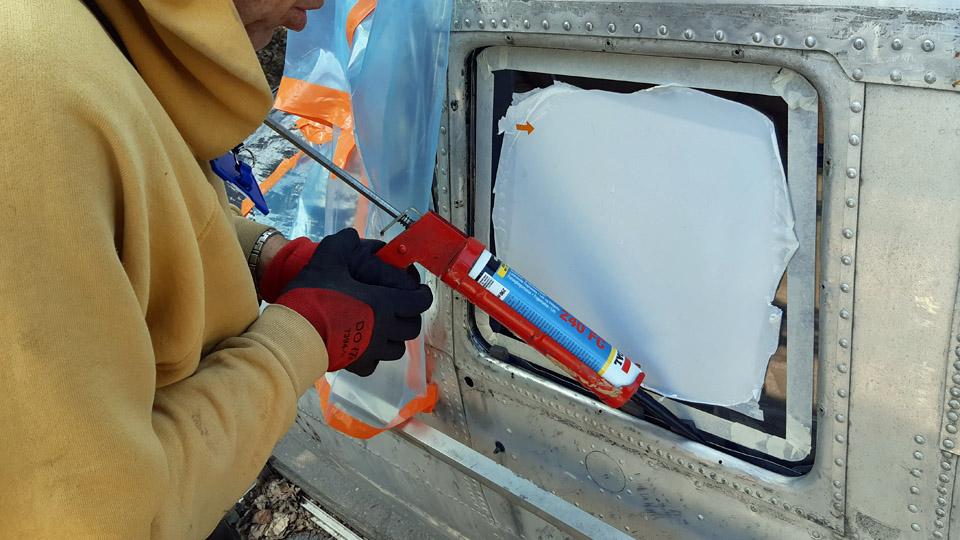
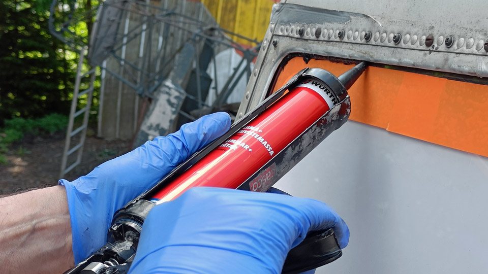
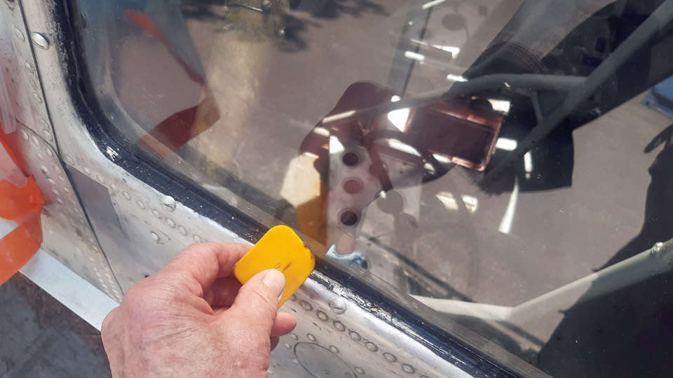
Photo by Lauri Veijalainen After the taping, the glue and sealant mass was squeezed out along the seam of the pane and the frame. After that the mass was formed even with a plastic forming spatula. As mass we used black Soudaseal and Würth glue and sealant mass. When the seaming was ready, we extracted the protective tapes along the pane edges and the protective film on the panes. The seaming of each pane turned out to be very neat.
Photo by Lauri Veijalainen There are also small sliding windows in the cockpit that can be opened. For them we received original framed panes from Airveteran Oy. Installing them proved to be a bit problematic. Both the sliding window frames lacked a locking screw from the bottom, with which the window was pressed with its rubber seal tightly against the frame to make it watertight. On top of that, both the frames of the sliding windows we received were both for the right-hand side. Luckily the right- and left-hand side pane differ from each other little enough, so we pushed the right-hand side pane deep and tightly enough into the grooves of the left-hand side frame. There it can remain for the time being, until we’ll find a suitable pane for it.
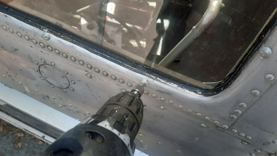
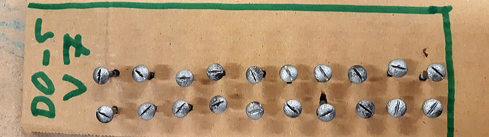
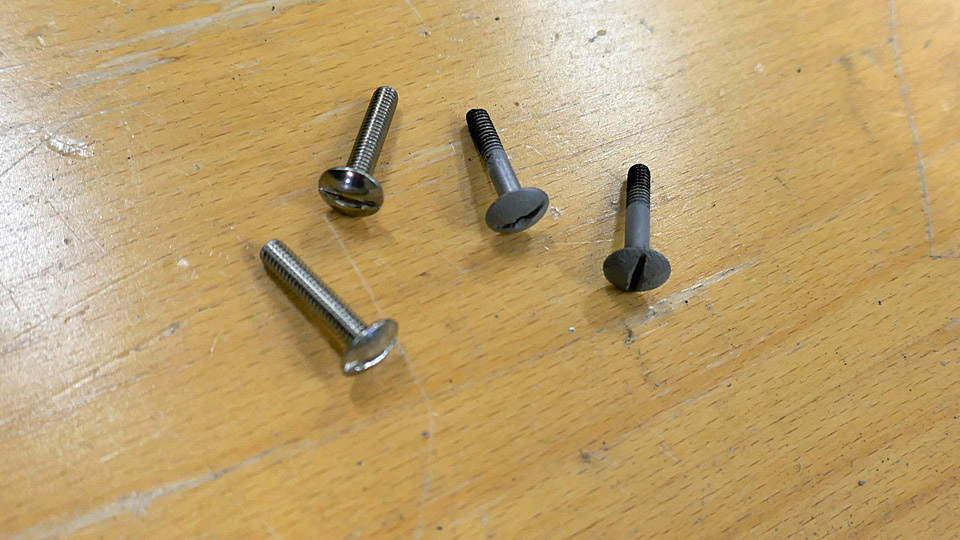
We noticed that along the windscreen and cockpit side window frames there were empty screw holes. What for, we wondered? To stop water from leaking into the fuselage, we blocked the holes by screwing groove-headed sheet metal aluminium screws into each of them.
Photos by Lauri Veijalainen
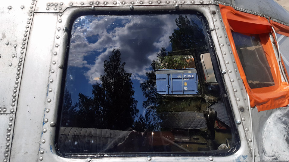
Photo by Janne Salonen With the windows we had accomplished all the agreed tasks to refurbish the DO-5, so for our part the fuselage was ready to be transported to Turku Airport and to be on show there at the Airshow on June 17th -18th. The DO-5 fuselage left for Turku on Thursday June 15th. Photos by Lassi Karivalo except if otherwise mentioned. Translation by Matti Liuskallio. |
|
Avainsanat: aviation history, restoration, Tuesday Club, C-47, DC-3, DO-5 |
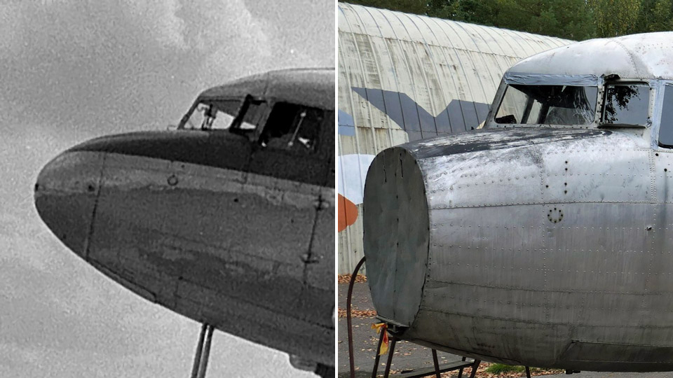
Making the lower part of C-47 (DO-5) nose coneLauantai 3.6.2023 - Tuesday Club member In an earlier blog I told that we were lent the lower half of a DC-3 (OH-VKC) nose cone to make the missing lower half of the DO-5 nose cone out of fibre glass. The DO-5 operated at its time in the Finnish Air Force as a jump aircraft for paratroopers. Aviation Museum Society managed to buy the DO-5, which was heading for scrap yard. Unfortunately the middle section of the wing is missing.
We needed the lower part of the nose cone on loan to make an outer surface fibreglass mould. With the help of the mould we’ll make the missing lower half out of fibreglass. Why do we make the lower half out of fibreglass and not of sheet aluminium? Simply because making the lower half out of aluminium is much more challenging and, on the other hand, because the fibreglass lower half of the nose cone fills its place well in the nose of the non-flying DO-5.
The lower half of the OH-VKC nose cone we loaned, and the DO-5 nose cone upper half are of the same DC-3 family, but they have been manufactured in different times and places. Because of this we still wanted to test, whether the OH-VKC lower half and the DO-5 upper half are a match. They weren’t an exact match, but close enough for us to use the loaned lower half of the nose cone to make a fibreglass mould.
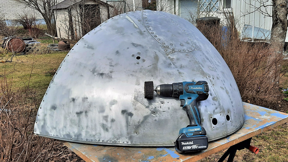
The first phase in making the fibreglass mould was to stiffen the lower part of the OH-VKC nose cone so that it wouldn’t distort when under work. This was because the lower half, made of thin aluminium sheet, detached from the nose of the OH-VKC is “sloppy” and won’t retain its form. A wooden cross stiffener was made between the opposite corners of the lower half. Then curved stiffeners in the form of the lower half edges were sawn out of 20 mm thick film plywood, which were attached to the edges of the lower half of the nose cone. The stiffeners were fastened by utilizing the existing attachment screw holes in the edges. Now the nose cone lower part will stay in form when handled.
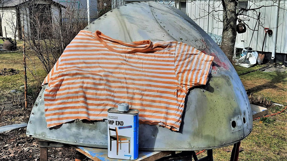
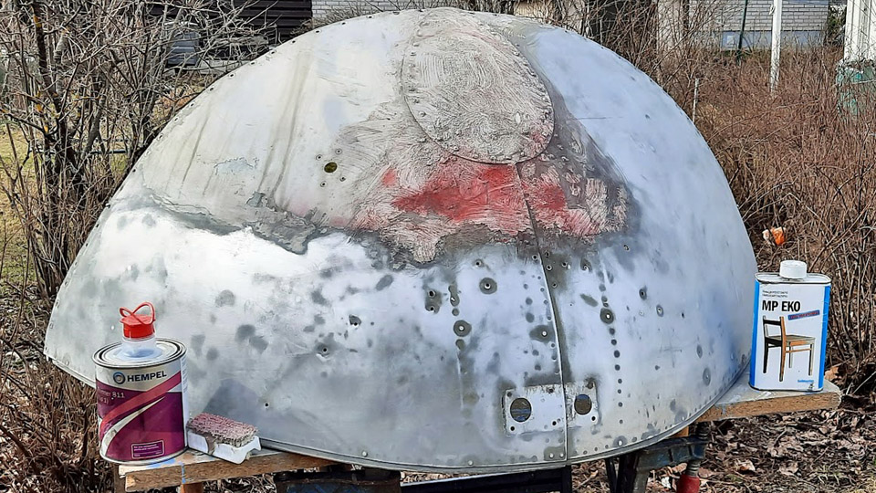
Photos by Reijo Siirtola Before making the fibreglass mould the bottom surface of the nose cone had to be cleaned into aluminium from the paint and filler covering it. The mottled history of the OH-VKC could be seen in the many layers of paint on the nose cone. An attempt to remove the layers of paint using a grinder failed because the sanding discs got choked instantly. Next a paint removing agent and scraping the paint off was tried. Suitable for our purposes proved to be Solmaster MP EKO Maalinpoisto (paint remover). Plenty of Solmaster was applied onto a restricted area of the aluminium surface and the area was covered with fabric to prevent evaporation. When the substance had worked a while, the paint could be scraped off with a wooden spatula. The wooden spatula worked well, and it doesn’t damage the aluminium surface of the lower half. Because the surface remained sticky, the final cleaning was done with thinner and xylene. In this way, phase by phase, the nose cone lower half’s surface was cleaned. Finally the surface was buffed with a nylon slip disc (Mirka nylon 60x30x6m).
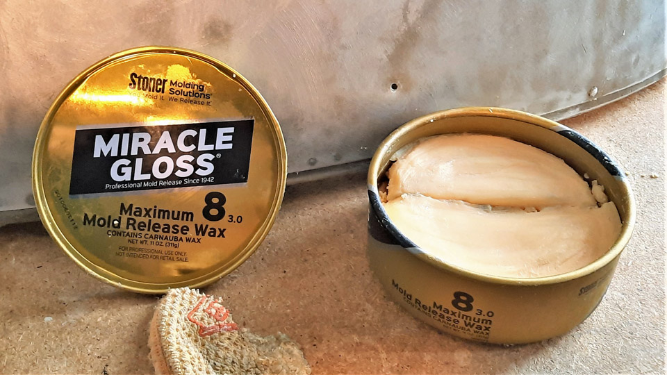
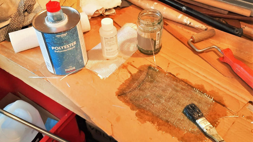
Photo by Reijo Siirtola Before layers of fibreglass fabrics, impregnated in polyester resin, could be applied on the surface of the lower half of the nose cone, the surface had to be carefully sealed. The sealing is important, because the sealer prevents the resin impregnated fibreglass mat from sticking on the aluminium surface below. Five layers of Miracle Gloss 8 sealer by Kevra Oy were rubbed on the lower half’s surface. Three first layers were rubbed on the cone surface with an interval of an hour, then a 12 hour pause, and finally the last two layers again with an interval of an hour. After 24 hours the lamination could be started. As lamination mat Biltema woven fibreglass fabric 30-512 was used, and as resin Biltema Polyester resin 36-0780”. The Polyester resin was chosen because its price was a shy quarter of the corresponding epoxy resin, and it won’t stick easily on the sealed surface of the mould.
Photo by Reijo Siirtola. Before the real lamination with fibreglass fabric, a test lamination with a small piece of fibreglass fabric was made. A piece of fibreglass fabric was impregnated with polyester resin while the piece of fabric was spread on cardboard. When the white colour of the fabric changed into transparent, it was turned over and polyester resin was applied on the other side, too. The cardboard from a cardboard box is an excellent base for this purpose. It’s strong enough to withstand the fibreglass mat to be impregnated with polyester resin and the resin won’t absorb into the cardboard to any significant degree. The piece of fibreglass fabric, impregnated with polyester resin, was “squeezed” tightly with a roller onto the surface of the lower half of the nose cone. The fabric stuck on well, and what was most important, after drying the fabric came off the next day without damage. So the sealing was a success.
Photo by Reijo Siirtola Now we could start to laminate the whole of the surface of the lower half with fibreglass fabric. For that purpose three pieces covering the lower half surface were cut out of the fibreglass fabric. First the surface of the lower half of the nose cone was completely covered with polyester resin. After that the first piece of lamination fabric was impregnated with resin and it was laminated on the surface of the lower half of the nose cone. Three layers of fabric were laminated. Finally on top of the layers thick ropes were laminated with polyester resin, which after drying would form a supporting structure keeping the mould in form.
Photos by Reijo Siirtola The next day the fibreglass mould could be detached. The detaching succeeded with ease, and no traces were left on the aluminium surface – thanks to the excellent sealer. Extra bits out of the edges of the mould were cut off. Slight unevenness was noticed on the inner surface of the detached mould. The uneven patches were sanded, and the surface was spackled with Biltema’s fibreglass filler (36-0137) and buffed. Thus the fibreglass mould had been finished for the lamination of the lower half of the nose cone.
Photo by Reijo Siirtola The lamination of the lower half of the nose cone began with the sealing of the inner surface of the fibreglass mould. After sealing the lamination was started, but this time with fibreglass mat. The reason for this was that with using of fibreglass fabric some unevenness seemed to remain, which necessitated extra buffing. With the fibreglass mat, which was pressed out of short glass fibres, the fibres criss-cross with each other. That gives a very smooth surface when laminated with a roller. Due to the structure of the mat it has also a good tensile strength in every direction.
Photo by Reijo Siirtola A piece covering the inner surface of the mould was cut. Polyester resin was first applied to the surface of the sealed fibreglass mould. After that the polyester resin impregnated pieces of fibreglass mats were laminated with a roll, one after the other, onto the inner surface of the mould. After the fibreglass had dried out the laminate was detached from the inner surface of the mould. It could be seen that the surface of the lower half of the fibreglass cone was remarkably smooth, nearly ready for painting.
Photos by Reijo Siirtola Because the fibreglass lower half of the nose cone wouldn’t hold its form without support, new supports cut out of thick plywood were installed. Thus it was secured that that the new fibreglass lower half of the nose cone stays in form when fitted on to the nose of the DO-5. The surface of the fibreglass lower half was spackled and sanded and primed with grey primer. When the lower half of the OH-VKC nose cone and the fibreglass lower half were put side by side, they looked identical, as was planned.
Photo by Juha Veijalainen
The new lower half of the nose cone was ready to be fitted onto the nose of the DO-5. During the fitting it will be seen how much we’ll have to work on its edges, so that we’ll be able to get it settle the way we want, against the upper half of the nose cone. To fit the lower half of the nose cone onto the DO-5 nose, we removed a sheet metal covering plate, which had protected the “cut off” nose. Behind it all sorts of rubbish, accumulated in the nose during the decades, was revealed and had to be cleaned off.
After cleaning we installed the upper half of the DO-5 nose cone in place and started fitting the fibreglass lower half in place. When fitting the lower half we noticed that the lower half was just within the tolerances, as we had hoped it would be. Naturally the edges of the lower half and the plywood supports inside had to be modified a few times so that the lower half of the nose cone was settled in the way we hoped, against the fuselage and the upper half.
The fibreglass lower half of the nose cone was ready waiting for the finishing coat of paint. At this stage it was painted grey and is allowed to stand out from the original upper half of the cone. If the DO-5 aluminium fuselage is to be polished at some stage, the fibreglass lower half of the nose cone will be painted with a paint that will emulate the aluminium surface. Photos by Lassi Karivalo except if otherwise mentioned. Translation by Matti Liuskallio. |
|
Avainsanat: aviation history, restoration, Tuesday Club, C-47, DC-3, DO-5 |
Caravelle towbar restoredLauantai 27.5.2023 - Tuesday Club member The original towbar for Caravelle III (SE-DAF), acquired from Sweden by Aviation Museum Society, was brought along. It was used by SAS. The towbar was abandoned by SAS along with the termination of the Caravelle fleet’s career. The towbar had lain decades at Arlanda Airport along SE-DAF.
The towbar was taken under restoration at the Tuesday Club in the autumn of 2022, in a similar fashion as the derelict Super Caravelle towbar was restored, used by Finnair. The SAS towbar is of the first version made by the Sud Aviation industries. For its part the Super Caravelle towbar used by Finnair is of the third and last version. The differences between these towbars are minimal and concern mainly the wheel rack of the towbar.
Along with the spring all the parts of the towbar were refurbished and painted. The last job before assembling the towbar was to repair the wheel rack to working order. When the towbar wheel rack was dismantled in the autumn season, it was noticed that the rim of the other wheel was so far gone that it was unusable. The other wheel’s rim was sound enough to be usable with a bit of welding. A new tyre and inner tube were bought for it and one of the bearings, which had broken when the wheel was dislocated from the axle of the wheel rack. When the rim had received its blue colour, the inner tube and the tyre were fitted in place.
To replace the unusable wheel, we managed, after a spot of searching, to find a wheel with an inner tube looking like the original wheel, and fitting the towbar’s 25 mm axle. A majority of the “wheelbarrow” wheels on sale were made for a 20 mm axle. When the rim of the new wheel had also been painted blue you could hardly tell them apart. The wheels were attached on to the wheel rack’s axles, after which the test assembling of the towbar could be commenced.
The test assembling will be necessary, because the towbar will be transported in parts to the Turku Airport area, where it will be assembled on show next to the ex SAS Caravelle SE-DAF, now being restored as the Finnair “Bluebird”. By test assembling it will be ensured that the assembling in Turku will take place without surprises.
The towbar test assembly was started by setting against each other the flanges of the halves of the towbar. We had to do some thinking, because the guiding pins for the flanges of the towbar halves didn’t line up with their holes so that the lifting handles are in the same line. We established that the towbar halves must have been 180 degrees out of line of each other already when they came to Finland.
This we hadn’t noticed when dismantling the towbar, because the towbar lacked the lifting handles, which would have indicated the position. If they had been there, we would have noticed that one handle was beneath the towbar, the other one above. So our conclusion is that the towbar was wrongly assembled at Arlanda. An indication of this is that in the photos we took before the dismantling of the towbar, the metal support of the towbar which should touch the ground is sticking to the skies.
To solve the problem of test assembling we sawed off the guiding pins and pressed the flanges of both the bar halves against each other so that the lifting handles were above the towbar and lined up properly with each other. After this the flanges were locked to each other with two locking collars around them. The collars were tightened fast by their brackets with bolts. This way the towbar halves had been connected.
Now it was time to attach the wheel rack to the towbar. The wheel rack was attached to the towbar by its attachment collars. The rack wasn’t attached in the middle of the towbar, but some way on the pull loop end side of the centre of gravity. Thus the aircraft towhead end, which connects with the nose gear, weighs down and leans on the ground by its support. Finally we attached the manufacturer’s plaque on the side of the towbar. The towbar is still lacking the Caravelle logo, which will be painted on its side before it will be ready to be delivered to Turku.
The derelict towbar underwent a complete transformation at the hands of the Tuesday Club. It changed from the rusty and partly damaged towbar into a renewed one, resembling the towbars used by the Finnair Caravelle fleet. It received the same appearance as the Finnair Super Caravelle towbar we restored a year ago. Photos by Lassi Karivalo Translation by Matti Liuskallio |
|
Avainsanat: aviation history, restoration, Caravelle, SE-DAF, Sven Viking;OH-LEA, Sinilintu, Bluebird;Tuesday Club |
DO-5 cabin to get new window panesTiistai 9.5.2023 - Tuesday Club member The windowpanes in the cabin of the DC-3 (C-47) – aircraft, owned by Aviation Museum Society, have gone opaque or non-transparent during the decades of storing in the woods. It has been decided to renew the panes. We’ll have time at the Tuesday Club to renew at least the port side panes before the Turku Airshow. The DO-5 fuselage will be on display at the Aviation Museum stand. The DO-5 panes will be renewed using UV-shielded polycarbonate plexiglass. It’s a lasting and easily workable material.
On both sides of the ”DAK’s” passenger cabin there are seven windows. The windowpanes are 47,7 x 34,9 cm in size. Their thickness is 5 mm. The panes have been fastened with 20 3,8 mm thick and 18 mm long roundhead grooved screws. The holes for the screws are situated in each window according to standard, at the same place. Between the frame and the pane there’s a 2 mm thick rubber seal. The seal has a speciality that it has holed rubber studs for each 11 mm hole. The studs press themselves into the screw holes so that the screws go through the rubber studs. The rubber studs prevent the screws being in direct contact with the plexiglass and operate as vibration dampers. The screws have been tightened against the plexi glass surface with nuts and washers, or instead of the washers with a supportive metal batten.
We started to renew the panes on the port side of the fuselage. At first we detached the pane from the window nearest to the door. One of the detachers was outside the fuselage and held the grooved screw in place with a screwdriver and the other one inside of the fuselage unwound the nut with care. The nuts had inch thread, so they were original. We detached all 20 nuts relatively easily and the screws were detached. The pane’s original rubber seal with studs appeared still to be in good condition, so it could be fitted back with the new pane. The empty window opening was covered from the outside with a plastic sheet fastened with duct tape. The detached rusty screws were cleaned, and their heads painted with anti corrosion paint.
When we continued detaching the panes, it was observed that that the screws of the remaining six windows had millimetre threads and were of various sizes, as if picked out of a junk box. Thus the screws aren’t original and fitted in the ”U.S of A”. Furthermore, the panes were without the rubber seals and attached only with less than ten screws instead of twenty. Because of this the window frames had empty screw holes for water to leak between the frame and the pane and to the cabin. Part of the panes were also thinner than the original ones. So it’s evident that DO-5 hasn’t flown with these panes assembled. The panes have most probably been fitted to the DO-5 cabin at Utti, when the fuselage was transformed into a ground training platform for paratroopers, or after the writing-off of the fuselage and abandoning it into the woods.
We decided to replace all the panes we had detached with 5 mm. thick plexi glass (as was the case in the original), 20 attachment screws and rubber seals. This means that we will have to buy seven panes of plexi glass, new attachment screws and some rubber mat for making the seals. Rubber seals with studs like the originals we are, however, unable to make. We bought the seven polycarbonate plexi glass panes sawn into measurements at ETRA. Because only one pane was original with original rubber seals, the 11 mm screw holes responding to the rubber studs will only be drilled to that. All the other six panes will be drilled holes for only 5 mm thick attachment screws, because these panes will be fitted with a 2 mm thick smooth rubber seal. We made a drilling frame out of a sturdy plate and battens, to drill the 20 screw holes into the panes in exactly the right spots. The drilling began into the plexiglass pane for the original window. The new plexiglass pane, still covered with a protective film, was placed under the drilling frame. On top of that was placed the original pane, which had 20 holes of 11mm in diametre for the rubber studs and attachment screws, which was meant as a drilling template. The panes were locked into the drilling frame with clamps.
To drill the holes precisely in the middle of the holes in the template pane, we lathed out of brass a drilling guide, which fits snugly into the 11 mm. hole. In the middle of the guide a hole was drilled for the 5 mm drill bit. The guide was placed into the 11 mm hole in the old pane, which was on top of the new plexi glass pane and through the guide a 5 mm preliminary hole was drilled into the pane under it. Thus a 5 mm hole was drilled into all the 20 holes. After this an 11mm bit was changed in the column drilling machine, and the template pane was removed from top of the new pane. The 11 mm bit was centred on the first 5 mm hole, and it was enlarged to 11 mm. Thus all the 20 holes were enlarged. After the drilling was done, the size of the holes was tested by fitting the rubber seal with studs from the original window to the new pane. The rubber studs fitted perfectly into the drilled holes.
The six other panes were made in a different way, because they will be fitted with a smooth 2mm thick rubber seal. Into these panes 20 holes were drilled with a 5 mm bit. This means that the panes’ screw holes will lack the vibration damping effect given by the studs, but on the other hand this DO-5 fuselage will never again fly, apart from a little shaking when moved about. When all the holes had been drilled to the new panes, it was time to make the rubber seals. A metre of 1,4 m wide rubber mat was bought from ETRA. Because the panes measure 47,7 x 34,9 cm. there’s enough material for eight seals, enough for a couple of extra ones. A funny thing happened when buying the mat; the shop assistant asked: ”would you like the smelly mat or the one without smell”? The brand without smell turned out to be double the price. To save Aviation Museum Society’s funds we bought the “smelly” brand. By Jove it did smell revolting, but soon the smell evaporated.
To cut the seals from the rubber mat for the six new plexiglass panes, a template out of plywood, exactly like the seal, was made. With the aid of the template the necessary six rectangular shaped rubber seals were cut. Now the seals lacked only the holes for the pane’s 20 attachment screws.
The screw holes were marked in each seal by using one new plexi glass pane as a template, into which 20 screw holes 5 mm in diametre had been drilled. The plexi glass pane with the screw holes was lined precisely on the rubber seal. A mark was made with a pen through each hole. After that the holes for the screws were made in the seal by using a leather piercer. This procedure was repeated on all the six seals.
We still had to find as many as possible new screws with a low round head and groove, resembling the original ones, with nuts and washers, to attach to the windows. You can’t find them in modern ironmongers’ anymore. Luckily the screws we were after could be found at Uudenmaan Pultti in Järvenpää. They were 4 mm thick and 20 mm long. With millimetre threads but being almost a match to the original 3,8 mm thick and 18 mm long screws. The heads of these new screws were painted in silvery grey, so that they wouldn’t stand out gleaming on the side of the DO-5 fuselage. Now everything is ready for the new panes to be installed to the port side windows of the DO-5 cabin. Photos by Lassi Karivalo Translation by Matti Liuskallio. |
|
Avainsanat: aviation history, restoration, Tuesday Club, C-47, DC-3, DO-5 |
The lower half of DO-5 nose cone on loan to fabricate a new oneSunnuntai 23.4.2023 - Tuesday Club member The fuselage of the Air Force C-47 (DO-5), which had been used for paratrooper training and is currently owned by Aviation Museum Society, is lacking the nose cone. The reason being that only the upper half of the cone survived and a lower half doesn’t exist in Finland for our purposes. Probably such an item could be found abroad for a load of money, but that form of action isn’t for us.
Left hand photo via Laskuvarjojääkärikilta. After pondering various possibilities to build the lower half of the nose cone at the Tuesday Club, we ended up in building the lower half out of fibreglass. The fibreglass lower half of the nose cone wouldn’t by all means be like the original, made of aluminium sheet, but resembles the original one, however. It would certainly be better than no nose cone at all. Now we have to find on loan an original “Dak” nose cone lower half, so that we could make a fibreglass mould with the help of the original lower half. Based on it we would make the fibreglass lower half of the nose cone. When installed, it would be painted in aluminium finish and simultaneously the upper half would be cleaned and polished.
The solution to acquiring an original lower half was found when the owner of the front fuselage of the ex Kar-Air DC-3 (OH-VKC), situated in Finland, promised to borrow us the lower half of the nose cone. So a group of DO-5 project members travelled en situ to dislocate the nose cone. For the most part we managed easily to detach the screws holding the lower half in the fuselage. We were helped by the preparatory work done by the owner of the OH-VKC front fuselage. A few screws had to be loosened by drilling.
In spite of the awkward working postures and the loose talking typical to us, the lower half of the nose cone was detached from the nose of OH-VKC in a couple of hours and the journey to the Finnish Aviation Museum began.
At the museum we fitted the lower half of the nose cone on loan and the DO-5 upper half together. They did match perfectly well, even though DO-5 is of the Douglas type C-47 or transport aircraft and OH-VKC is an original passenger aircraft. We established the lower half of the nose cone on loan to be perfectly suitable for making a fibreglass mould. Before we get that far, the lower surface of the lower half on loan has to be ground clean of dirt as well as the paint and filler on its surface.
Our aim is that the complete nose cone will be in place in the DO-5 fuselage, when it will be on show at the Aviation Museum Society’s stand at the Turku Airshow on June 17th -18th. Photos by Lassi Karivalo except if otherwise mentioned Translation by Matti Liuskallio. |
|
Avainsanat: aviation history, restoration, Tuesday Club, C-47, DC-3, DO-5 |
Ilmailumuseot.fi - Aviationmuseums.fi